Blog
MV Terminations | Incompetency & Substandard Jointing Plumbs Another New Depth
July 11th, 2019
Contributed By: Watkins and Jacomb Construction Power & Consultancy
Uploaded By: Chris Dodds – Thorne & Derrick: Distributors of LV, MV & HV Cable Jointing, Cable Terminations, Substation & Electrical Eqpt
WJCPC are specialist LV HV Cable Termination & Jointing contractors with over 20 years experience in the High Voltage Electrical Industry covering the utilities, renewable energy, rail, data centre and general industry sectors – UKPN competent for LV & HV Termination and Jointing Of Cables, Confined Spaces, Substation Entry and Cable Fault Finding.
In the following post Ben Jacomb, Director of WJCPC, highlights several shortcomings and the dangerous consequences of clients failing to carefully vet and selectively employ Competent Cable Jointers.
WJCPC were asked to attend site to remove a total of 16 incorrectly specified and installed cable glands and install correct type brass glands. Due to the cable termination being a larger diameter to permit the existing and replacement cable glands to be changed WJCPC had to carefully remove the anti-track heat shrink (red insulation) from the heat shrink terminations.
After first inspection WJCPC were unsatisfied with the cable jointing technique undertaken to remove the semi conductive layer from the MV cable: this was done by using a semi-con stripping tool, the semi conductive layer is semi bonded so the stripping of the layer should be stripped by using a depth knife and the ringing of the stress control point by a soft file.
Any marks left in the XLPE insulation by the Jointer will influence the magnetic fields inside the MV cable and should be removed by emery cloth to leave a smooth finish eliminating any voids. If the heat shrink tube is shrunk on top of a void there will be moisture and where there is moisture there will be arcing, burning and then failure.
If the semi conductive layer is not removed correctly at the crucial point discharges occur and can damage the medium voltage cable and safe operation of the power network.
Below are WJCPC’s site observations.
Incorrect cable gland installed
The cable installed is a 11kV single core power cable with XLPE insulation and 120sqmm stranded copper conductors (16sqmm earth wires) – the original cable glands installed were 50mm plastic glands which are over-sized and incorrect for the cable diameter consequently failing to provide adequate mechanical retention.
Also, due to the cable being a backup supply from generators the vibrations will evidently loosen the cable gland until it is effectively and dangerously removed from the gland plate of the cable box which will then allow the cable to move around within the termination box – this could potentially loosen the cable termination connection.
This could do serious damage within the generator.
New 40mm brass cable glands were installed to the correct specification and that corrective action by WJCPC now has eliminated any vibration and loosening of the connection issues.
Observations
Ensure that when ordering jointing materials that manufacturers recommendations and specifications are met to eliminate incorrect installations.

Incorrect Cable Gland Installed
Over-Crimped Cable Lugs
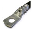
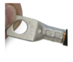
All 16 of the site 11kV cable terminations had been over compressed or “crimped” due to the Jointer using an incorrect crimping die set.
Over compression of the cable lugs caused a distinct gap between the cable lugs and the cable insulation.
| Incorrect Cable Lug Compression | Correct Cable Lug Compression |
 |
 |
- Choose a manufacturer providing crimp tooling die set and lugs matched to work together to give assured crimping performance.
- Each lug should be clearly marked with a reference on the barrel or palm which enables the user to verify that the lug selected is the correct size and type for the conductor. The manufacturer’s name or logo also allows the correct die set and crimp tool to be selected from their recommended list.
- Prepare the conductor by stripping the insulation back so that, when assembled, it cannot be trapped in the barrel of the lug. The strip length should be equal to that of the barrel. Take care to avoid damage to the conductor strands during the stripping operation. Exposed conductor strands should be cleaned to remove any particles of insulation.
- Fully insert the conductor into the barrel. If an inspection hole is provided, check the conductor is fully inserted.
- Crimp the lug in accordance with the manufacturer’s instructions. Pay careful attention to the positioning of the die on the barrel and, if multiple compressions are required, the sequence in which they are made.
- For further information visit Cembre | Cable Lugs & Crimping Tools.
Examine The Completed Cable Crimp Lug To Check
- Marking on cable lug shows it is correct for the conductor type and size.
- The marking on the cable lugs show the correct die set was used.
- No insulation is trapped in the cable lug barrel.
- Excess grease is removed from insulation and lug.
- If an inspection hole is provided, the conductor has been fully inserted
- It is NOT to be over-compressed causing excessive flash or burrs, which are detrimental to the performance of the joint.
It is NOT under-compressed, as this is detrimental to the performance of the joint.
If any doubt exists, samples should be produced for test purposes.
Poor Cable stripping
of semi conductive layer
The semi conductive layer of the MV cable has been stripped by a stripping tool and on one occasion the stripping tool has impeded past the manufacturer’s requirements for their insulation diameter which will cause a void within the cable termination – the void could cause a hotspot and potential flash over which will render the connection irreparable.
The semi conductive layer is semi bonded (easy peel) so the semi conductive layer should be removed using a specialist Jointers tool or depth knife – here the semi con layer has been removed from the cable using a bonded semi-con layer stripping tool and it has left a poor finish to the XLPE insulation.
Even if the semi con layer is bonded type then the cable jointer should use 3 stage emery cloth ( 80, 120, 240 grit) to sand out any ridges and voids and then clean down the cable with a non- conductive cleaning cable wipe.

Poor Stripping By The Jointer Of The Semicon Layer Of The MV Cables
The XLPE insulation finish on easy peel type cables should be a nice smooth finish without ridges, undulations or jagged surfaces.
The semi con round off point should be a perfect finish as this is the most crucial point of the cable termination – if this is not perfectly smooth and the void filler mastic is not installed properly this can affect the stress relief from electrical fields.
It is essential this is undertaken by the Jointer with due care and attention.
Below is a photo of potential damaged caused by above non-conformances.
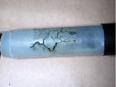
Missing earth strands from cable
On 50% of the cables WJCPC found missing earth strands. This will degrade the earthing protection for that cable.

Missing Earth Strands From Cable
Poor outer sheath strip
The outer sheath on occasions was poorly removed and not stripped according to the manufacturers jointing instruction – this may affect the damp seal which is installed on the outer sheath and the cable terminations measurements may come out of sync and affect the electrical connections durability.

Poor outer sheath strip
Conclusion
After full inspection WJCPC found that poor Jointing and sub-standard workmanship without quality control had introduced serious and potentially catastrophic operational issues into the medium voltage cable and power system network.
WJCPC recommend that a survey onsite is conducted to check more cable terminations as they suspect this will be a continuous issue onsite – using a thermal camera and partial discharge tester can help determine any cable terminations that need to be looked at and maybe pick some at random to strip down and visually inspect.
Due widespread concerns about industry workmanship, lack of Jointer training and declining standards, WJCPC can provide an audit service to visually audit jointers and ensure they are completing their termination to the manufacturers jointing instruction – this may not eradicate Jointer incompetency but it will contribute to a reduction in the volume of poorly installed cable joints.
There is also another process you can introduce and this is a step-by-step photo sequence of the termination installation at its crucial stages – this does not take long and captures the poorly installed cable joints or terminations before they are energised.
➡ Please Note: The cable glands WJCPC have changed and the re-termination of the cables will not be guaranteed by WJCPC due to the terminations not being installed to the manufacturers instructions. WJCPC have terminated them to their best ability but only as a temporary measure to allow the generators to be commissioned.
WJCPC strongly advise these cables are removed and new cable and new terminations installed immediately.
HV Cable Terminations
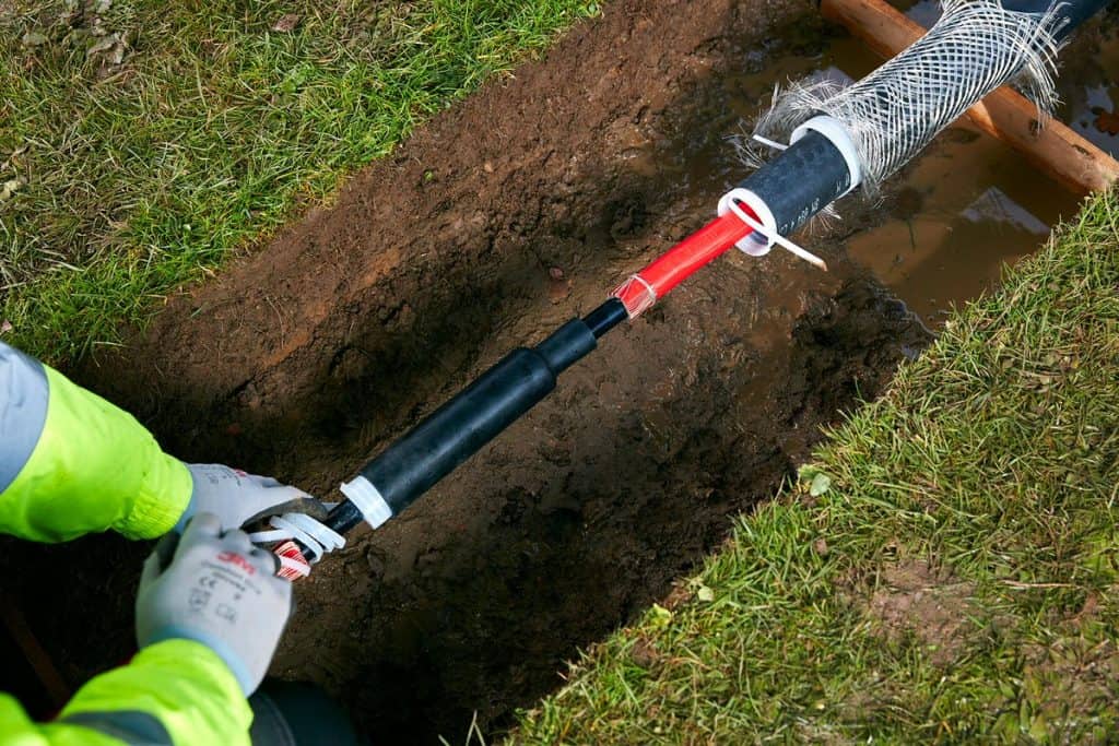
Thorne & Derrick distribute the most extensive range of HV Cable Terminations & Joints to suit 11kV/33kV medium and high voltage power cables, including indoor cold shrink and heat shrink terminations, outdoor pole-mounted terminations or separable connectors for gas insulated equipment applications.
HV High Voltage Cable Joints | Cable Terminations | Cable Connectors | MV HV 11kV 33kV

Joint | Terminate | Connect Medium & High Voltage Cables MV HV
THORNE & DERRICK are national distributors of Cable Installation, Jointing, Substation & Electrical Safety Equipment MV HV – we service UK and global businesses involved in cable installations, cable jointing, substation, overhead line and electrical construction at LV, 11kV, 33kV and EHV.
Contact us for 3M Electrical, ABB, Alroc, AN Wallis, CATU Electrical, Cembre, Centriforce, CMP, CSD, Elastimold, Ellis Patents, Emtelle, Euromold, Filoform , Furse, Lucy Electric & Zodion, Nexans, Pfisterer, Polypipe, Prysmian, Roxtec, Sicame, WT Henley.

Invitation
Thorne & Derrick invite you to join LinkedIn’s largest LV-HV Electrical Discussion Group : Low & High Voltage Power, Cabling, Jointing & Electricals.
Discussion subjects include cable installations, cable jointing, substation, overhead line and electrical construction at LV, 11kV, 33kV and EHV. Network, engage and promote your profile, company or products with over 10,000 influencers.


15kV/17.5kV Type Test Reports | 3M Cold Shrink QS1000 Cable Joints & Splices
July 8th, 2019➡ QS1000 are Cold Shrink Joints/Splices manufactured by 3M Electrical – the 3M QS1000 cable joints for single and 3 core cables are tested and rated to 15kV/17.5kV.
3M Electrical have a full type test report to 11kV for the cable joints – also 3M Electrical have type tests to show that the QS1000 splice bodies are tested to 15kV. The QS1000 splice is used in both the single, and 3 core joints, and the impulse level tests are relevant to show that all joints using the QS1000 are rated to 15/17.5kV.
Test Report | Cold Shrink | Single Core Cables MV HV Joints up to 15kV/17.5kV
Test Report | Cold Shrink | 3 Core Cables MV HV Joints up to 15kV/17.5kV
Information confirmed by 3M Electrical.
Should you require any assistance with the selection or specification of Joints & Terminations for use with MV HV cables please contact us.

EPR Cable With Bonded Semicon Screen | MV HV Cable Stripping & Jointing Tools | Alroc CAMF4
July 2nd, 2019
Alroc Tools – Cable Jointing Tools (MV HV)
Video Demonstration: Stripping Bonded Semicon From EPR Insulated Cables MV HV
In the following demonstration video the Alroc CAMF4 tool is shown with the LFNS blade removing bonded semicon screen from medium voltage power cable with EPR insulation.
Thorne & Derrick International are specialist distributors and stockists of Alroc – high quality cable preparation and  jointing tools for use with medium/high voltage power cables.
T&D distribute Cable Jointing Tools from leading manufacturers including Alroc, Ripley, Boddingtons and Hivotec for all types of LV, MV or HV cable stripping, preparation and jointing requirements
THORNE & DERRICK INTERNATIONAL
LV, MV & HV Cable Installation, Jointing, Substation & Electrical Equipment Distributors.
IEEE 1584 Arc Flash Standard | An Interview with Jim Phillips P.E., MIET
June 25th, 2019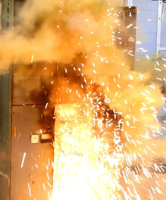
IEEE 1584
Arc Flash Standard
Special thanks to Rebecca Frain CMgr FCMI Tech IOSH (Managing Director – Electrical Safety UK Ltd) for allowing Thorne & Derrick to publish her interview with Jim Phillips regarding the new IEEE 1584 2018 Edition.
What Is IEEE 1584?
IEEE 1584, published by the IEEE Standards Association, is A Guide for Performing Arc-Flash Hazard Calculations.
This guide provides mathematical models for designers and facility operators to apply in determining the arc-flash hazard distance and the incident energy to which workers could be exposed during their work on or near electrical equipment.
By Rebecca Frain
This week I had the opportunity to interview Jim Phillips regarding the new IEEE 1584-2018 Standard and what to expect with some of the new changes. In addition to being Associate Director for Electrical Safety UK and founder of Brainfiler.com, Jim is also Vice-Chair of IEEE 1584 and International Chair of IEC TC 78 – Live Working.
IEEE 1584 – IEEE Guide for Performing Arc Flash Hazard Calculations was first published in 2002 and is the standard that defines the equations and methods used in many of the arc flash software packages used for arc flash risk assessments. The second edition was published towards the end of 2018 and is a real game changer.

RF: A question many of us have is why did it take 16 years to publish the second edition of this standard?
JP: It has been a long journey. The timeline had many phases during this epic project. The first couple of years were spent developing a test plan and raising money from contributors for this enormous (and expensive) project. This was followed by preliminary tests that we call “Scouting Tests” These were used to help define the direction of the entire testing program.
After the preliminary tests, it took several more years for the project team to complete the main arc flash tests and develop the new model. That phase of testing was completed in 2012 and included over 1800 new arc flash tests. Quite an accomplishment. The 2002 edition of the standard was based on around 300 tests.
After the testing and model development phase, the IEEE 1584 working group created a model review task group to review and validate the new model. This took several more years of effort. During that time there was lots of fine tuning to further improve the accuracy. We completed it all in 2016 when it was now time for the formal balloting process. An interesting side note, the new standard passed on the very first ballot – we were all amazed. However, there were also over 1000 comments from the balloters that we had to address. Needless to say, this took some time to resolve. The second edition of this landmark standard was finally published on November 30, 2019
RF: What has changed with the 2018 edition?
JP: (laughs). It’s actually easier to answer the question “What did not change?” The standard still has the same title. With only a few exceptions, just about everything else is very different. This means what you previously knew about the IEEE 1584 standard can be tossed out.
RF: What is the single biggest change?
JP: That one is easy. The introduction of electrode configurations. The 2002 Edition had only two configurations: 1) An arc flash in an enclosure and 2) An arc flash in open air. Both were based on the test electrodes in a vertical configuration.
There are now five different electrode configurations: Vertical electrodes in an enclosure (VCB) and in air (VOA) which are the same as the 2002 standard but we also have horizontal electrodes in an enclosure (HCB) and in air (HOA) and vertical electrodes in an enclosure terminating in an insulating barrier (VCBB). The idea is the new configurations provide greater flexibility for modeling actual equipment.
RF: How does that affect the risk assessment?
JP: Depending on where the arc flash occurs and the type of equipment, the orientation of the electrodes, can affect the trajectory of the plasma and incident energy that reaches the worker. There is some guidance provided in the 2018 Edition of the standard.
RF: I assume there are other big changes?
JP: Yes. There are adjustments for different enclosure sizes. The enclosure size can have quite an effect on the incident energy. If an arc flash occurs in a smaller enclosure, the arc energy is more focused resulting in greater incident energy reaching the worker. If the enclosure is larger, the energy is not as focused and less energy reaches the worker. As a result, the tests included new enclosure sizes and the development of an enclosure size correction factor for the calculations.
RF: Anything else?
JP: The standard now uses interpolation and extrapolation to fine tune the results and provide better accuracy. There is also a new more detailed calculation for determining the minimum arcing current during an arc flash. The past standard simply used a fixed 85 percent value to determine the minimum.
The new equations are much more complex including a thirteenth-degree polynomial with thirteen coefficients that are selected based on the voltage and electrode configuration. (I hope I didn’t scare anyone away with that comment) The good news is the software takes care of the difficult math for us. The list of changes goes on.
RF: How does this all affect the results from previous studies?
JP: I have a series of worksheets that I developed and use to illustrate the calculations and compare with the 2002 edition. Some calculation results are similar to 2002. However, some can be quite different. It has quite a bit to do with the electrode configuration and other factors such as enclosure size.
RF: Does this change way arc rated clothing and PPE is selected?
JP: The overall risk assessment process is the same as before. i.e. Arc rated clothing and PPE are selected with an arc rating sufficient for the calculated incident energy. However, the difference is with the incident energy calculations using IEEE 1584. The calculations and modeling have changed dramatically.
Arc rated protective clothing is based on the standards: IEC 61482-1-1 and IEC 61482-2. There are a few other IEC standards for arc flash protection as well. These standards are from the IEC TC 78 Committee that has a group of highly knowledgeable and talented experts from around the globe all working towards developing and maintaining product standards for greater worker safety.
RF: We are looking forward to hearing more about the 2018 Edition of IEEE 1584 on September 24 at the upcoming International Arc Flash Conference in Manchester.
JP: Thank You Becky! I am looking forward to it. See you soon!

Arc Flash International Conference -Manchester Airport Tuesday 24th September
Company Profile
Electrical Safety UK Ltd
Electrical Safety Management is our core business. We provide expert consultancy and advice for blue chip organisations across Europe concerned with the safe management of risk associated with all electrical work activities. ESUK provide a multi-faceted holistic approach including a full electrical safety management program, project management and policy documentation all bespoke to the client’s requirements including fully accredited and bespoke training courses and personnel assessment programmes.
Here at Electrical Safety UK, our team delivers a range of professional services to customers in a variety of Market sectors. The team prides itself on the quality of the services it delivers to companies at the heart of manufacturing, engineering, energy, food production and education in the UK and Europe.

ESUK Services include:
1 Electrical Safety Management – Specialist consultancy and advice concerned with the safe management of risk associated with all electrical work activities. ESUK offer a multi-faceted approach including a full electrical safety management program, full project management and policy documentation bespoke to a client’s requirements.
2 Electrical System Studies – ESUK are the UK’s foremost exponent of Arc Flash Technology and carry out a wide range of power system studies, including Fault Level Analysis to IEC and ANSI standards, Protection Coordination, and complex Arc Flash Risk Assessments.
3 Training – ESUK offer both accredited and bespoke training courses including City & Guilds, IOSH, Safety Pass Alliance, Energy and Utility Skills. ESUK are also registered with the EEIAS and CIPD for recognition and accreditation of bespoke training courses.
Contact Details
Electrical Safety (UK) Limited
2 Genesis Business Park
Sheffield Road
Rotherham
S60 1DX
Tel: 0800 652 1124
Tel: 01709 961 666
Email: [email protected]
LV, MV & HV Jointing, Earthing, Substation & Electrical Eqpt
Thorne & Derrick International are specialist distributors of LV, MV & HV Cable Installation, Jointing, Duct Sealing, Substation & Electrical Equipment – servicing UK and global businesses involved in cable installations, cable jointing, substation, overhead line and electrical construction at LV, 11kV, 33kV and EHV.
THORNE & DERRICK Product Categories: Duct Seals | Cable Cleats | Cable Glands | Cable Jointing Tools | Cable Pulling | Earthing | Feeder Pillars | Cable Joints LV | Joints & Terminations MV HV

Isolate 99.999% Of Electrical Risk Using VeriSafe from Panduit #E5
June 25th, 2019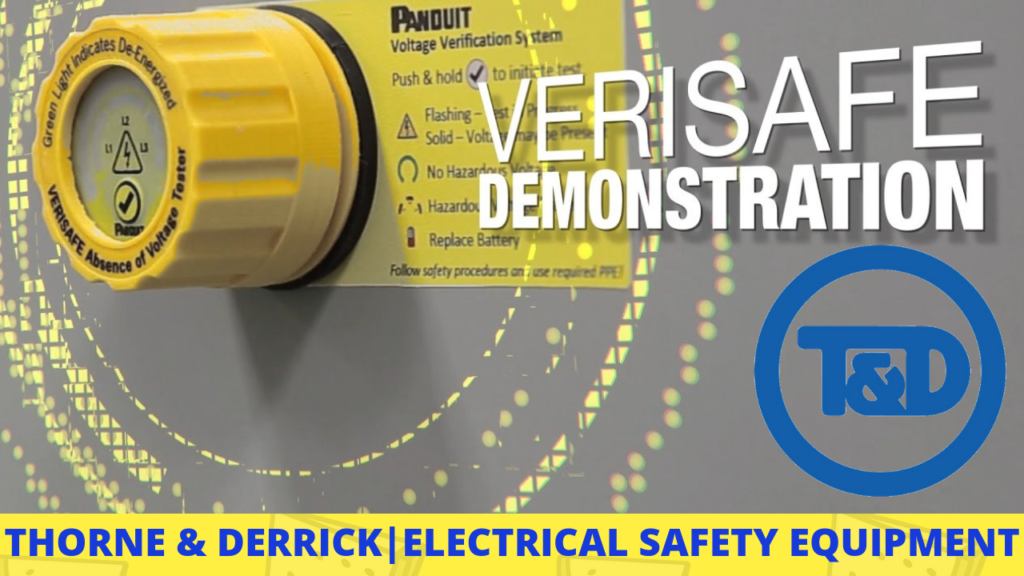
-
uploaded by Chris Dodds - Thorne & Derrick Sales/Marketing Manager
Safe Electrical Isolation
Thorne & Derrick International, a Panduit Channel Partner, based in the UK and Specialist Distributors of Electrical Safety Equipment are delighted to provide this following Product Endorsement of Panduit Verisafe by Craig O’Neill of Steve Willis Training Ltd.
Initially sceptic but nevertheless open-minded Craig wanted to learn more – so we arranged a product demonstration.
➡ VIDEO How To Verify Total Absence of Voltage By The Push Of a Button
” Verisafe is an electrical safety product manufactured by Panduit that automatically isolates electrical control panels and distribution boards.The risk of arc flash is an incredibly dangerous problem – arc flash incidents and blasts can vaporise someone in a split second. Having worked in substations for the early part of my career I was always terrified of being responsible for electrical isolation. One false move and it’s too late.” comments Craig.
“Verisafe eliminates 99.999% of this risk and should be implemented to every panel as a first step to isolation procedures. My concerns initially was the device picking up inductive back emf and other induced currents but the demonstration carried out by Glen Bate (Panduit IEI Account Manager) proved it can detect these.”
“Verisafe even detects when a phase has lost connection!”
“I am very good at finding product faults or shortcomings but so far I’ve found none.”
“The electrical safety device needs maintenance like any product but if put in a professional environment, this could easily be implemented into regular checks. Safe electrical isolation is a lesson we drum into our learners at Steve Willis Training Ltd because high standards of professionalism is at the heart of what we do. Electrical safety is at the forefront of being a professional and so it fits right in with our ethics and we were very pleased to have Glen Bate visit and discuss it with us. The students really had a good think about safe isolation after he left and it really helped move the us up a peg on the professional ladder.”

SWT Specialists In Building Engineering Services Training
Who Are Steve Willis Training Limited?
We are specialists in building engineering services training with over 18 years’ experience at our first class training  centres in Burgess Hill, West Sussex and Portchester, near Portsmouth. Our training ranges from short courses for tradespeople to full apprenticeships and retraining for those leaving the armed services.
We treat you as an individual, finding the perfect course to suit your needs based on your requirements, experience and qualifications – we’ll never sell you a course you don’t need. We have an excellent reputation – most of our business comes from repeat customers and personal recommendation – and we are approved by all the industry bodies.
We are proud to be an EU Skills approved centre for our IGEM/IG/1 compliant gas managed learning programme, City & Guilds approved for our electrical training, and an OFTEC approved oil training centre.
Steve Willis Training Ltd
Unit F2, Sheddingdean Industrial Estate
Marchants Way, Burgess Hill
West Sussex, RH15 8QY
- Tel Email
- 01444 870860 or 02392 190190
- [email protected] or [email protected]
#WednesdayWisdom Take advantage of 15% discount on selected electrical courses for 2019/20 if you book by 5th July: https://t.co/CFkC1zIzJX call 01444 870860 / 02392 190190 to book pic.twitter.com/fFrgvL91qU
— SteveWillisTraining (@Steve_WillisLTD) June 12, 2019
Thorne & Derrick
T&D are Specialist Distributors to UK Distribution Network Operators (DNO’s), NERS Registered Service Providers, ICP’s and HV Jointing Contractors of an extensive range of LV, MV & HV Jointing, Earthing, Substation & Electrical Eqpt – this includes 11kV/33kV/66kV joints, terminations and connectors for both DNO and private network applications.
Contact our UK Power Team for competitive quotations, fast delivery from stock and technical support or training on all LV-HV products.
Key Product Categories: Duct Seals | Cable Cleats | Cable Glands | Electrical Safety | Arc Flash Protection | Cable Jointing Tools | Cable Pulling | Earthing | Feeder Pillars | Cable Joints LV | Joints & Terminations MV HV
➡ Read: Thorne & Derrick Announce Distribution Agreement & Contract With Nexans