

Cable Cleats
Important Factors You Need To Consider When Working With Cable Cleats
May 24th, 2022
Cable Cleats
A cable cleat is designed to ensure that cables are fixed, retained and supported correctly so that in the event of short circuit fault or any other emergency, they will contain the cables without causing damage; enabling the circuit to be restored once the fault has been dealt with.
One of the most important issues to consider when specifying cable cleats is the risk of material corrosion – not just as a result of the installation environment, but also from other metals which the cable cleat may come in to contact with.
Read more about the affects of corrosion in our evidence based specification case blog – Stainless Steel Cable Cleats – Preventing Galvanic Corrosion Of Cable Fixings
All cable cleats distributed by Thorne & Derrick are undergoing testing to conform to the latest IEC 61914:2021 Standards. Certification will be in place before the deadline.
What Else Is Important To Consider When Working With Cable Cleats?
Operating Temperatures
Ellis’s standard ranges of cable cleats are designed for use in ambient temperatures ranging from -50°C to +60°C and with cable conductor temperatures up to 90°C.
Eddy Currents
Ferro-magnetic materials that completely surround single conductors in AC circuits are susceptible to heating from eddy currents.
Generally, eddy current generation at mains frequencies requires a complete electrical and ferro-magnetic circuit around each conductor. However in installations where all three phases are contained within the same cable cleat e.g. three cables in a trefoil cable cleat, the magnetic fields of the phases cancel each other out, which in turn negates the eddy currents and the heating effect.
Despite this, it is preferable to use cable cleats manufactured from non-magnetic materials such as aluminium, injection moulded polymers or stainless steel, which has only very slight magnetic properties.
ALWAYS REMEMBER: When using single cable cleats manufactured from ferro-magnetic materials care should be taken to avoid forming a complete iron loop around the cable.
Multi-core Cables
There is a commonly held belief within the electrical industry that multi-core cables will protect themselves in the event of a short-circuit, meaning their installation does not require fault rated cable cleats.
However, research shows that the forces between the conductors of a multi-core cable in the event of a fault are similar to those between three separate single core cables laid in a trefoil arrangement.
Therefore, when specifying multi-core cables it is advisable that cable manufacturer should be contacted to ascertain the ability of its specific cable to withstand these forces.
It is worth noting that whatever the withstand quoted, in the event of a significant fault an unrestrained multi-core cable will move.
Furthermore, the requirements of most wiring regulations are clear and typically state that:
“Every conductor or cable shall have adequate strength, and be so installed as to withstand the electromagnetic forces that may be caused by any current, including fault current.”
Fire
There are currently no European or IEC standards for fire rated cable clamps, although there are requirements within other standards that can be followed to prevent unsuitable products being specified.
The international standard IEC 61914 requires non-metallic and composite cable cleats to have adequate resistance to flame propagation.
UL94, the standard for Safety of Flammability of Plastic Materials for Parts in Devices and Appliances, is a plastics flammability standard that classifies plastics according to how they burn in various orientations and thicknesses. Adherence to its V-0 rating for polymers should be demanded by specifiers.
The use of the description LSF (low smoke and fume) is common terminology with regard to polymers, but is misleading as it doesn’t relate to any published standard and so can be interpreted in a wide variety of ways.

Rail Cable Cleats
To ensure complete assurance of performance in a fire, all Ellis plastic products have undergone testing at the Building Research Establishment (BRE) in line with the London Underground 1-085 specification with regard to:
- Smoke emission
- Limited oxygen index
- Toxicity of fumes
The appropriate products are listed in the London Underground Approved Products register. Identification numbers are 360, 361,362, 363, 364, 365 and 1661.
A great deal of focus is placed on fire rated (FP) cables and their performance in fire, but very little attention is given to the cable fixings used to secure these cables. Given that FP cable is typically rated for operation in temperatures ranging from 850°C to 950°C then the use of plastic cable cleats or clamps is clearly inappropriate.
Even aluminium only has a melting point of 660˚C, which means it would fail to support FP cables in a fire.
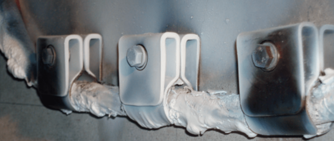
Cable Cleats | Fire Resistant Cables
To counteract this shortcoming, Ellis manufactures the Phoenix range of clamps for use with FP cables. Independently tested by Exova Warrington fire and BRE, all products in the range are proven to perform to the same level as the FP cables ensuring continuous operation in the event of fire.
UV Resistance
While wholly metal cable cleats are impervious to UV attack, composite and polymer cable cleats can be at risk.
Ellis composite cable cleats such as Emperor, Vulcan and Atlas all have polymer liners, but are designed to be impervious to UV attack because the polymer is shielded by either the cable cleat’s body or the installed cables.
Polymer cable cleats that are likely to be exposed to UV should be supplied in materials containing carbon black or other UV stabilised material.
ALWAYS REMEMBER: All cable cleats supplied by Ellis Patents for applications involving UV are provided in UV resistant materials.
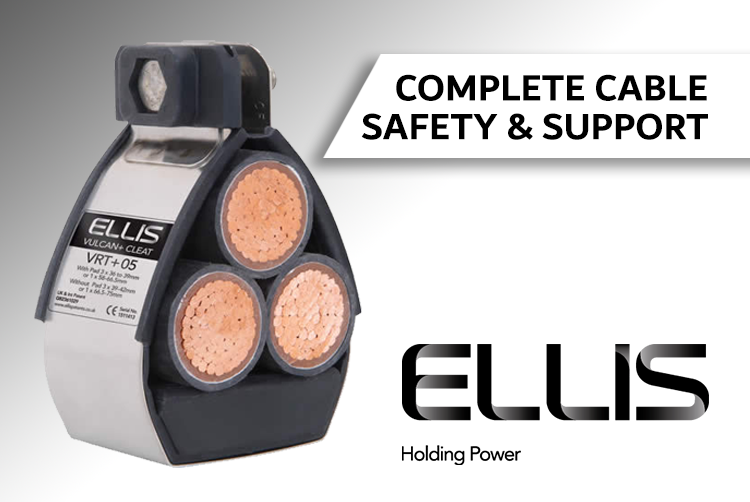
Do Ellis & Thorne & Derrick provide any advice on cable cleat system designs?
As a cable cleat manufacturer, Ellis Patents do not offer advice on the design principles and choices between different types of cable installation. We will however provide expert advice on the suitability of particular cable cleats within any type of installation.
Flexible and Rigid Cable Installations
On most projects a major consideration is the constant movement of the cable due to thermo-mechanical effect. To accommodate this two principal types of installation design exist:
FLEXIBLE SYSTEMS – where the cables are “snaked” either vertically or horizontally. The cable can expand and contract freely between fixing points.
RIGID SYSTEMS – where the cables are rigidly fixed. The longitudinal thermo-mechanical force is withstood by the combination of the stiffness of the cable, the cable cleat reaction force and the rigidity of the support structure.
Cable cleats are designed to withstand the forces exerted by the cable in the ‘axial’ direction, this is relevant to both flexible and rigid systems. It is also important when the cables are installed vertically.
Flat, Trefoil and Quadrafoil Installations
Cable arrangements for three phase installations utilising single conductor cables are typically flat spaced, flat touching or trefoil.
The Wiring Regulations (BS7671) provides current ratings and voltage drop values for all these arrangements. It also contains information on grouping factors and spacing between circuits to achieve thermal independence.
Additionally, IET Guidance Note No. 6 delivers valuable advice on installation arrangements where there are multiple cables per phase.
An additional method for installing single-core cables is to use quadrafoil cable cleats where the neutral is bundled with the three phase conductors. In this arrangement, there is no advice in BS7671 but a report produced by ERA on behalf of Ellis delivered the following guidelines:
Current ratings, given in BS7671, for cables in touching trefoil formation are appropriate for cables in quad bundles
Derating factors, given in BS7671, for cables in touching trefoil formation are appropriate for cables in quad bundles
Voltage drops for circuits in quad formation should be calculated using the values tabulated in BS7671 for cables in flat touching formation
When considering multiple cables per phase, the advice given in Guidance Note No.6 for trefoil groups is applicable to quad bundles
The induced voltage in the neutral conductor of a quad group is minimal and can be ignored.

Quadrofoil Cable Cleats – Ellis Patents Vulcan Quad
How do I prevent thread galling when installing cable cleats?
Stainless steel fasteners have a propensity to “pick-up” when the two threaded surfaces slide against each other. If sufficient speed and pressure is applied to the sliding surfaces then they can weld themselves together – a phenomenon known as thread galling.
All stainless steel fixings will thread gall if there is sufficient friction.
To avoid thread galling, reduce the speed and downward pressure when closing fasteners and use lubrication where appropriate.

THORNE & DERRICK
Thorne & Derrick are national distributors of LV, MV & HV Cable Installation, Jointing, Substation & Electrical Equipment – servicing businesses involved in cabling, jointing, substation, earthing, overhead line and electrical construction at LV, 11kV, 33kV, 66kV and EHV. Supplying a complete range of power cable accessories to support the installation and maintenance of low/medium and high voltage power systems:
- Slip-on Cable Terminations
- Cold-shrink Cable Terminations
- Heat-shrink Cable Terminations
- Cable Joints – Heat & Cold-shrink
- Separable Connectors (Euromold)
- Surge Arresters & Switchgear/Transformer Bushings
Key Product Categories: Duct Seals | Cable Cleats | Cable Glands | Electrical Safety | Arc Flash Protection | Cable Jointing Tools | Cable Pulling | Earthing | Feeder Pillars | Cable Joints LV | Joints & Terminations MV

T&D Deliver Their Largest High Voltage Power Cable Cleat Order
May 24th, 2022Press Release | June 30th 2022
Thorne & Derrick, a Specialist Distributor for Ellis Patents, have delivered their largest contract to date to supply cable cleats to provide safety and reliability to high voltage power cable circuits.
The order includes a project total of over 10,000 units of their market-leader cable cleat, The Emperor. The cable cleats will be installed to provide the highest levels of short circuit protection to high voltage power cables. Following several client meetings, Thorne & Derrick were awarded the purchase contract despite market-wide challenges including raw material price volatility and supply chain strains.
This current project award is testament to our ability to utilise the in-house expertise of Ellis Patents to design project specific, bespoke solutions for customers on tight delivery schedules and builds upon recent project successes in the renewable, rail, data-centre and utility substation sectors.
“Emperor was preferred to competitors due to the products established track record and its evidenced compliance to the rigorous IEC 61914: 2015 standard. The ability to demonstrate product performance in similar harsh operating environments with past project references was critical. Ellis Patents have an international reputation to commit and meet customer delivery requirements – trust in the customer-supplier relationship was central to securing the business. We are now working with Ellis on several custom engineered cable clamps and support solutions – the commercial and technical support by Ellis Patents to Thorne & Derrick was outstanding and instrumental in securing this prestigious project order for both our companies,” comments Chris Dodds (Sales & Marketing Manager at Thorne & Derrick.
The Emperor of Cable Cleats
The Emperor is a heavy duty compact stainless steel cable cleat designed, developed, tested and manufactured in accordance with IEC 61914. The cleat is available in an extensive range of sizes with range taking ability to suit cables installed to containment in single or trefoil formation. The frame of the cleat is manufactured from corrosion resistant grade 316L stainless steel, the cable is supported by a liner manufactured form a low smoke zero halogen (LSOH) material. The closure fixings are manufactured from grade A4-70 stainless steel. The Emperor can be fixed to the supporting structure by either two M10 fixings or one M12 fixing. Non standard cleat designs can be supplied upon request.

ES Single Range | 32-150mm diameters with short-circuit test levels to 235kA at 225mm cleat spacings

ER Trefoil Range | 19-128mm diameters with short-circuit test levels to 195kA at 300mm cleat spacings

Cleating 3 Times Faster
Ellis Patents are an outstanding manufacturer innovator of products to drive down life cycle costs, including their Twist-Foot design of cable cleats which is typically 3 times faster to install than using conventional fixings.
Jonny Hewitt from Thorne & Derrick with Noman Shabir from Ellis Patents at the Dogger Bank – Meet The Buyer Event.

Key Product Categories: Connectors, Joints & Terminations MV HV | Cable Preparation & Jointing Tools | Duct Seals | Cable Transits | Cable Cleats | Cable Glands | Electrical Safety | Arc Flash Clothing & Protection | Cable Pulling | Earthing & Lightning Protection | Feeder Pillars
Thorne & Derrick distribute the most extensive range of MV HV Medium & High Voltage Cable Joints, Terminations & Connectors from manufacturers including 3M, Prysmian, Nexans Euromold, Elastimold, Pfisterer CONNEX & SEANEX.

Cable Cleats | Importance, How To Specify & International Standards
May 9th, 2022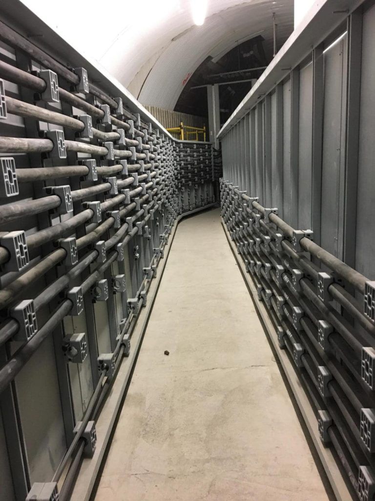
What Are Cable Cleats?
“A cable cleat is a device designed to secure electrical cables when installed at intervals along the length of the cables” – IEC 61914 Cable Cleats for Electrical Installations
“Cable cleats should:
Prevent excessive cable movement due to fault-current magnetic forces
Be rated for specific cable size and available current.”
The fifth edition of API Recommended Practice 14F (Design, Installation and Maintenance of Electrical Systems for Fixed and Floating Offshore Petroleum Facilities).
“Single core electric cables are to be firmly fixed, using supports of strength adequate to withstand forces corresponding to the values of the peak prospective short-circuit current.” – Lloyds Register. Rules and Regulations for the Classification of Ships, Part 6, Control, Electrical, Refrigeration and Fire.
“Cables are to be installed and supported in ways to avoid chafing and undue stress in the cable.” – ABS Steel Vessel Rules 4-8-4/21.9 Cable Support, 4-8-4/21.9.1 General and 4-8-4/21.9.3 Clips, Cable Saddles, Straps
“In order to guard against the effects of electro dynamic forces developing on the occurrence of a short-circuit or earth fault, single core cables shall be firmly fixed, using supports of strength adequate to withstand the dynamic forces corresponding to the prospective fault current at that point of the installation.” DNV Rules for Ships / High Speed Light Craft and Naval Surface Craft, Pt. 4 Ch. 8 Sec.10 – page 68, C50
ALWAYS REMEMBER: Any power cable system designer or installer has an obligation to consider the method of securing cables in order to restrain their movement whether caused by an electrical fault or any other reason – a job that can only be safely and securely done with correctly specified cable cleats.
HOW TO SPECIFY A CABLE CLEAT?
- Calculate the system peak fault current
- Identify the specification of the cable to be used including the nominal cable diameter and the manufacturing tolerance
- Identify the support structure type e.g. Ladder ( including rung spacing), basket, individual steel structure etc
- Consider support structure material type e.g. stainless steel, galvanised steel etc
- Consider the environmental conditions
- Consult with Ellis Patents who will provide you with the most cost effective solution for your needs
WHAT IS THE INTERNATIONAL STANDARD FOR CABLE CLEATS?
IEC 61914 Cable cleats for electrical installations outlines a series of tests that can be used to assess the performance of a cable cleat’s design.
Although the standard does not define pass or fail levels, it allows manufacturers to define the performance characteristics of their products, and specifiers to compare products from different manufacturers.
The aspects of construction and performance covered by the standard include:
- Material type – i.e. metallic, non-metallic or composite
- Minimum and maximum declared service temperatures
- Resistance to impact at the minimum declared operating temperature
- The ability of the cable cleat to withstand axial slippage forces
- Resistance to electro-mechanical forces – i.e. the ability of the cable cleat to withstand the forces between the cables in the event of a short-circuit
- Resistance to UV and corrosion
- Flame propagation
TRANSPORT FOR LONDON PROJECT

Working with Ellis Patents we completed the specification and have now moved into manufacturing for our largest contract to date to supply TfL (London Underground) approved cable hangers across several depot modernisation projects.
Thorne & Derrick in consultation with the Asset Manager at Transport for London and their appointed Telecoms & Power contractor secured formal Authorisation & Approval for the Pegasus range of non-metallic cable support hangers. The product will provide safe cable management of the cable route within the Bridges & Structures category – over 1000 hangers with proven lifecycle performance and utilising the standard J-type design for support of multiple cable runs including single, 3-way and 5-way configurations are now scheduled for delivery.

Thorne & Derrick are Approved Vendors to both Network Rail and Transport for London
THORNE & DERRICK
Thorne & Derrick are national distributors of LV, MV & HV Cable Installation, Jointing, Substation & Electrical Equipment – servicing businesses involved in cabling, jointing, substation, earthing, overhead line and electrical construction at LV, 11kV, 33kV, 66kV and EHV. Supplying a complete range of power cable accessories to support the installation and maintenance of low/medium and high voltage power systems:
- Slip-on Cable Terminations
- Cold-shrink Cable Terminations
- Heat-shrink Cable Terminations
- Cable Joints – Heat & Cold-shrink
- Separable Connectors (Euromold)
- Surge Arresters & Switchgear/Transformer Bushings
Key Product Categories: Duct Seals | Cable Cleats | Cable Glands | Electrical Safety | Arc Flash Protection | Cable Jointing Tools | Cable Pulling | Earthing | Feeder Pillars | Cable Joints LV | Joints & Terminations MV
Cable Cleats | A Device For Short Circuit Protection | CPD Course By Ellis Patents
March 29th, 2022
Cable Cleats
A Device For Short Circuit Protection
Ellis Patents, the world’s leading cable cleat manufacturer, has launched its UK accredited Continuing Professional Development (CPD) course – developed in-house, their online CPD course has helped educate thousands of engineering professionals from around the world.
“Cable cleats: a device for short circuit protection” is a NBS RIBA accredited course designed to provide technical insight and guidance that has been adapted for international use and is available through Ellis’s e-learning portal.
register Here
➡ FREE CPD Course By Ellis Patents
Find Out More
Cable Cleats CPD Course Content
Module 1 Introduction
Includes a brief history of standards plus the importance of detailed specification to ensure the correct cable fixings are chosen for the environmental conditions and application.
Module 2 Electrical Theory
Nothing too heavy! Learn about short circuit faults, why they occur and their impact on cable systems. Also, how to calculate the forces involved and therefore how to ensure the correct strength fixings are specified.
Module 3 Materials
Different applications require differing solutions. Learn how sunshine, pollution and marine environments can cause problems if the wrong materials are specified. How to avoid bimetallic issues and how to prevent corrosion. The importance of fire safety and low emissions is also studied.
Module 4 Testing
Some exciting video clips of when things go wrong, and of good engineering practice. Appreciate the international standards that apply to cable cleat design and the rigorous testing procedures involved.
Module 5 Applications
An overview of some cable cleating applications and interesting special cable fixing projects.
What are the people saying?
“The Ellis CPD training is beneficial because it covers technical aspects of selecting the right cleat and it allowed me to discuss cleats with much more confidence.”
Rob Rehberg (NASCO)
“I found the Ellis Cable Cleats CPD kept my interested, it was very informative and professionally put together.”
Jon Watkins (Electrical Engineer – Kier Construction)
In this video Ellis Patents compare using Stainless Steel Cable Cleats and Stainless Steel Cable Ties – the Ellis cable cleats are used to restrain power cables on slotted rung cable tray and are short-circuit tested to 59kA RMS, 118kA Peak for 0.1 second duration.
SHORT-CIRCUIT TESTING
There is a major difference between the short-circuit withstand requirements of a cable and the short-circuit withstand of a cable cleat.
The former is concerned with cable degradation as a result of temperature rise (thermal stress heating), while the latter is concerned with cable retention as a result of electromechanical forces.
Typical installation specifications that have been derived from the thermal withstand of the cable would require a short-circuit withstand of 63kA for 1 second or 40kA for 3 seconds.
A short-circuit test for a cable cleat does not consider this heating effect, and instead concentrates entirely on the destructive electro-mechanical forces at peak, followed by a short term decaying RMS.
The international standard IEC 61914 requires a short-circuit test duration of just 0.1 second. This equates to five complete cycles, by which time the true strength of a cable cleat will be known.
IEC61914 notes “a cable cleat is provided with a means of attachment to a mounting surface but does not rely on an unspecified mounting surface for the retention of the cables. Examples of mounting surfaces that may be specified are ladder, tray, strut or rail, wire and beam. Where declared, cable cleats provide resistances to electromechanical forces.”

IEC61914 – Calculating Short Circuit Forces To Specify Compliant Cable Cleats
Further Reading
- WITHDRAWN IEC 61914:2009 | Cable Cleats for Electrical Installations
- Cable Cleats from Ellis Patents | Better By Design
- Cable Cleats & Fixings For The Rail Industry by Ellis Patents
- Cable Cleats – Costs v Quality
- Cable Cleats & Safe Cable Installations for the Wind Energy Industry
THORNE & DERRICK
Thorne & Derrick are national distributors of LV, MV & HV Cable Installation, Jointing, Substation & Electrical Equipment – servicing businesses involved in cabling, jointing, substation, earthing, overhead line and electrical construction at LV, 11kV, 33kV, 66kV and EHV. Supplying a complete range of power cable accessories to support the installation and maintenance of low/medium and high voltage power systems:
- Slip-on Cable Terminations
- Cold-shrink Cable Terminations
- Heat-shrink Cable Terminations
- Cable Joints – Heat & Cold-shrink
- Separable Connectors (Euromold)
- Surge Arresters & Switchgear/Transformer Bushings
Key Product Categories: Duct Seals | Cable Cleats | Cable Glands | Electrical Safety | Arc Flash Protection | Cable Jointing Tools | Cable Pulling | Earthing | Feeder Pillars | Cable Joints LV | Joints & Terminations MV
Cable Clamps by BAND-IT
March 22nd, 2022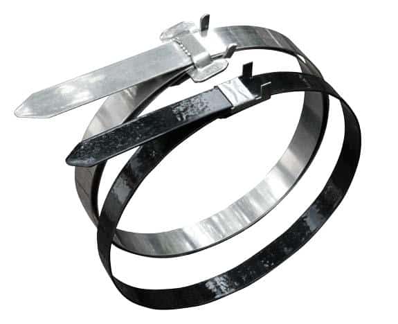
Clamping Cables
From traditional metal cutting, stamping and forming, to robotic precision forming and sorting, BAND-IT is paving the way for new manufacturing solutions.
BAND-IT’s in-house engineering team expands the traditional applications and invites the challenges new opportunities have to offer.
Thorne & Derrick have stocked and supplied the BAND-IT range of cable clamps, ties and fasteners since 1985.
With over 75 years’ experience in stainless steel clamping, strapping, banding, bundling, fastening, and identification solutions, we can modify standard clamping systems or develop new solutions for your specific project needs. From customized clamp selection to in-depth field testing and specification, BAND-IT’s engineered applications team and Thorne & Derrick can meet the exacting requirements for your specialized needs.
- Standard and state-of-the-art high speed production tools and fastening solutions
- Unrivalled R&D and engineering support for the BAND-IT product range
- Worldwide manufacturing and distribution facilities
- On call Engineered Applications Team to meet your project needs
Need a custom solution to solve your cable fastening challenge?
All of BAND-IT’s custom stainless steel clamping and cleat solutions for cables are manufactured to provide the highest level of quality and can be customized to:
- Cable clamp easily conformable to any shape
- Securely fasten dissimilar materials, odd shapes and difficult objects
- Withstand extreme temperatures and corrosive conditions
- Stainless steel, high-strength, cable fastening and fixing clamps resist vibration
BAND-IT has engineered cable clamping and fastening solutions for applications in areas such as LV MV HV cable management, hose attachment, identification, insulation and pole and tower mounting in the utility, power and transmission distribution sectors.
More from BAND-IT
- Solar Farms Replace Nylon Cable Ties With Metal Cable Ties
- BAND-IT Band Clamps Used In TR-343 Transducer Assembly
- BAND-IT ULTRA-LOK Cable Clamps Reduce Cable Theft | Case Study
- Securing Fire Resistant Sleeves On Hoses & Wires With BAND-IT JS Clamp
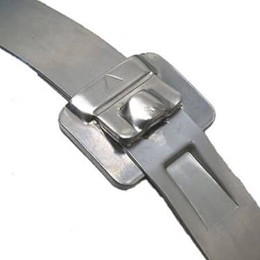
Cable Clamps by BAND-IT

Thorne & Derrick distribute the most extensive range of Low & High Voltage Cable Installation & Electrical Distribution Equipment to the Power Transmission & Distribution industry in the onshore and offshore wind, solar, rail, oil/gas, data centre, battery storage and utility sectors – this includes Joints, Terminations & Connectors to enable the installation of low, medium and high voltage power cables into underground trench or duct.


