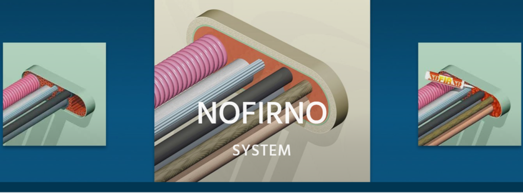
RISE NOFIRNO sleeves and sealant by CSD Systems are made from the highest grade silicone materials, and have a tested service life of over 20 years. Unlike some competitive systems, the RISE NOFIRNO system contains no cheap calcium silicate or mineral wool blankets, which can absorb moisture and cause corrosion of the penetration collar and pipes inside the collar. This problem is referred to as “Corrosion Under Insulation” (CUI).
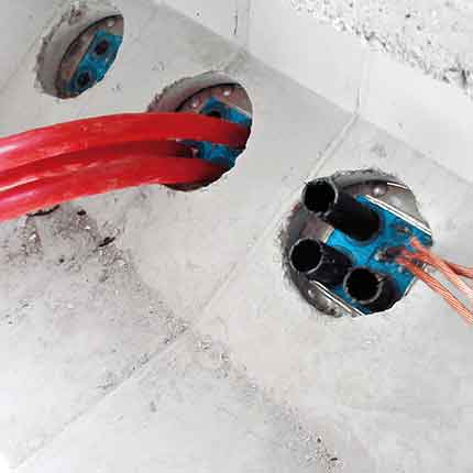
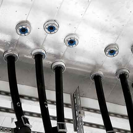
The CSD NORFIRNO is a Single & Multi Pipe Penetration Sealing System composed of a steel sleeve (length 180 mm or 250 mm) welded or bolted to steel deck or bulkhead, NOFIRNO Filler Sleeves filling the open space between sleeve and pipe – one of the most adaptive systems for sealing straight and angled pipe penetrations and can even accommodate multiple pipe runs, significantly saving in space and weight.
The NOFIRNO system is Type Approved for the harshest ratings for A, H and Jet Fire Class, and is also approved for watertight, gas-tight, blast and shock applications.
RISE NOFIRNO System Features
Approved for harshest fire ratings for pipe penetrations (EN, A, H and Jet Fire class)
Allows substantial movement of the ducted pipes within the conduit
High pressure ratings – designed for gas and/or watertight penetrations
Prevents “Corrosion Under Insulation” (CUI)
Longest service life and best Total Cost of Ownership of any sealing system
NOFIRNO® rubber sleeves and sealant will remain stable and not be consumed by fire
Approved for any combination of cable and/or metallic, GRP or plastic pipes
For insulated copper pipe penetration, RISE/ULTRA shell of thickness 2.5 mm shall cover the insulated pipes over a length of 210 mm.
For Multi-Mix Pipe, RISE/ULTRA strips/sleeves around the plastic pipes.
The penetration is sealed on both ends with a layer of 20 mm NOFIRNO Sealant.
Rise Nofirno Application/Limitation
Single pipe penetrations
Approved for A-0 penetrations for steel, copper and GRP service pipes of following maximum sizes:
Steel: Ø408 mm; Copper. Ø420 mm; GRP: Ø408 mm.
See drawings Nos. R0207E Rev.2 and R0213E Rev.1.
Approved A-0 to A-60 penetrations for insulated (Armaflex AF or equivalent) copper pipes of outside diameter up to Ø54 mm and for Insulated steel pipes up to Ø168 mm.
Maximum sleeve size: Max. Ø273 mm.
See drawings Nos. R0246E Rev.1, R0247E Rev.1, R0248E Rev.1 and R0249 Rev. 0.
Multi-pipe penetrations
Approved A-0 to A-60 single and multi-pipe penetrations for steel/stainless steel pipes up to Ø408 mm, for Cu/CuNi pipes up to Ø420 mm and GRP pipes up to Ø408 mm. Maximum sleeve size: Max. allowable surface area: 2500 cm2 (500 mm x 500 mm). See drawings Nos. N0009E Rev. 2 and N0011E Rev. 2
Approved A-0 to A-60 single and multi-pipe penetrations for steel/stainless steel pipes up to Ø168 mm and for Cu/CuNi pipes up to Ø108 mm.
Maximum sleeve size: Max. allowable surface area: 3000 cm2 (1000 mm x 300 mm). See drawings Nos. N0018E Rev. 2 and N0020E Rev. 1
Approved A-0 multi-pipe penetrations for steel/stainless steel pipes up to Ø219 mm.
Maximum sleeve size: Max. allowable surface area: 1800 cm2 (600 mm x 300 mm).
See drawings Nos. N0045E dated 04.06.12
Multi-Mix pipe + cable penetrations
Approved A-0 to A-60 penetrations for a mix of cables up to Ø105 mm (incl. CLX and LAN cables), steel/stainless steel pipes up to Ø168 mm, for Cu/CuNi pipes up to Ø108 mm and plastic pipes (PVC, PP, PPR, HDPE, PB, PVDF) up to Ø160 mm.
Maximum sleeve size: Max. allowable surface area: 3000cm2 (1000 mm x 300 mm). See drawing No. N0015E Rev.2, N0016E Rev.2 and N0017E Rev. 2.
The installation of the pipe penetration is to be in accordance with the manufacturer installation manual and referenced drawings.
For A-0 divisions, no insulation is needed on the sleeves and the pipes.
Approved for watertight penetrations up to a design pressure of 1.66 bar. Approved for airtight penetrations up to a design pressure of 1.00 bar.
The penetration system is generally not to be used for penetrating boundaries of tanks.
When pipe penetrations is requested to be used in watertight bulkheads on passenger ships and Special
Purpose Ships (SPS), the pipe penetration system has to comply with the requirements given in SOLAS (2009) Ch. II-1 Reg. 13.2.3 c.f. IMO Res. MSC.429(98) Reg. 13.2.3.4. Pipe penetrations passing through watertight bulkheads are subject for separate examination.
Each product is to be supplied with its manual for installation/application and maintenance.
NOFIRNOis one of BEELE Engineering’s ‘rapid cable and pipe sealing systems’ for use on board ships, on offshore pipework installations, in building and construction and other environments where the safety of people and installations has to be guaranteed.
Type Examination Documentation
Test report No. R0209 dated July 2008 from Efectis Netderland BV (TNO).
Test report No. R0325 dated July 2008 from Efectis Netderland BV (TNO).
Test report No. R0556 dated July 2008 from Efectis Netderland BV (TNO).
Test report No. 0303-010 dated 21 March 2003 from Beele Engineering.
Test report No. 0501-039 dated 11 January 2005 from Beele Engineering.
Test report No. 0609-056 dated 19 September 2006 from Beele Engineering.
Test report No. 0712-060 dated 12 January 2007 from Beele Engineering.
Test report No. 0702-061 dated 01 February 2007 from Beele Engineering.
Test report No. 0704-067 dated 18 April 2008 from Beele Engineering.
Test report No. 0706-070 dated 26 June 2008 from Beele Engineering.
Test report No. 0805-080 dated 21 May 2008 from Beele Engineering.
Test report No. 1206-104 dated 05 June 2012 from Beele Engineering.
Pressure test report No. 0203-D056 dated 01 March 2005 from Beele Engineering.
Tests Carried Out Tested according to IMO FTPC Part 3 (IMO Resolution A.754 (18)) and in accordance with IMO 2010 FTP Code Ch. 8.
Marking of Product
The product or packing is to be marked with name and address of manufacturer, type designation, fire technical rating, MED Mark of Conformity and USCG marking if applicable.
Thorne & Derrick are national distributors of LV, MV & HV Cable Installation, Jointing, Substation & Electrical Equipment – servicing businesses involved in cabling, jointing, substation, earthing, overhead line and electrical construction at LV, 11kV, 33kV, 66kV and EHV. Supplying a complete range of power cable accessories to support the installation and maintenance of low/medium and high voltage power systems:
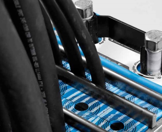
Roxtec cable seals are used in cable vaults, duct banks, electrical substations, trenches and M&E building services protecting low, medium and high voltage power systems against numerous external risk factors including fire, gas, water, cables, pressure, electrical, particles and blast.
Electromagnetic shielding
Why do you have to protect critical LV MV HVinfrastructure equipment against EMI, IEMI, EMP and HEMP? How can you both seal and secure the electromagnetic shield? There are many questions regarding electromagnetic threats.
Roxtec are happy to be able to provide answers – and cable transit solutions.
Their skills and expertise enable the correct solution to be chosen that has electromagnetic shielding alongside fire, gas and water ingress certification.
What is EMI, IEMI, EMP and HEMP?
EMC refers to good electromagnetic compatibility.
Disturbances can be attributed to electronics like computers and mobile phones.as well as war or acts of terror. They can majorly affect electrical equipment and critical power supply to hospitals, banks and server halls, and a blackout can be very expensive.
EMI – electromagnetic interference
IEMI– intentional electromagnetic interference
EMP – electromagnetic pulse
HEMP – high altitude electromagnetic pulse
The Roxtec ES sealing system
The Roxtec ES sealing system provides an effective protection when used in shielded environments. It diverts conducted disturbances, shields against radiated disturbances and provides a mechanical and environmental protection against fire, gas, water, dust, dirt and rodents.
HEMP protection
Roxtec can help you protect equipment against the effects of HEMP, a high-altitude electromagnetic pulse caused by a nuclear weapon far above the surface of the earth. HEMP causes chaos through electromagnetic pulses. It makes transformers explode and can cause breakdown of the entire power grid.
Verifying shielding effectiveness
At the Roxtec test lab, we use shielded rooms, antennas, transmitters and receivers to verify the ability of our seals regarding attenuation of radiated interferences. The cable seals have undergone numerous shielding attenuation and transfer impedance tests.
Established since 1985, T&D distribute the most extensive range of LV, MV & HV Cable Jointing, Terminating, Pulling & Installation Equipment – contact us today for a competitive quotation.
Typical applications are Ex e and/or Ex tb rated electrical enclosures such as transformers, motors, generators and junction boxes.
Ex e means increased safety for explosive gas atmospheres, and Ex tb means explosion protection by enclosure for explosive dust atmospheres.
Hazardous Area Zone Classification
Hazardous areas are rated into zones based on the possibility of occurrence of an explosive atmosphere – it is the obligation of the owner or the operator of a facility to ensure that the zone classification is done by authorized personnel.
Hazardous Area Cable Seals
Highlighted zones = Permitted zones for Roxtec Ex products
The Roxtec Ex product range includes a wide variety of pipe and cable seals to handle different cable sizes and openings. The sealing products are designed and certified for use in Zone 1 and Zone 2 for gas (including vapour and mists) and Zone 21 and Zone 22 for dust.
Cable Sealing Standards
Roxtec Ex solutions are tested, approved and certified according to the following standards:
Specialist Distributors of Industrial & Hazarodus Area Equipment to provide Power, Heat, Light & Ventilation to the explosive atmospheres and process industries.
White Paper : Humidity Effects in Substations By EA Technology (Download Here)
Author Tony Byrne, January 2013
Consequences For The Technical Specification of Cable Sealing Systems
Roxtec are global-market leaders in the innovation, design and manufacture of cable transits and pipe penetration sealing systems.
Roxtec solutions effectively seal cables, cable ducts and pipes against water and dust ingress into safety critical and sensitive electrical equipment and buildings.
Cable Transits
In this White Paper, Roxtec highlight the potential for electrical equipment failure resulting from high relative humidity within high voltage substations typically operating at 11kV, 33kV, 66kV and 132kV voltages.
Roxtec commissioned EA Technology to produce a report on the causes and effects of high relative humidity within indoor substation environments and methods of mitigation.
This influential report covers Relative Humidity and the effect it has on the inception or level of partial discharge (PD).
The White Paper discusses the factors affecting the environment within a high voltage substation and the best practice for the design of substations and internal environment control.
The findings in this White Paper have wide-reaching implications for the effective technical specification of cable and duct sealing systems.
Cable sealing systems can reduce the risk of high voltage electrical equipment failure caused by partial discharge as a result of inadequate specification of cable transit systems.
The report concludes, “cable entry points are one of the main sources of water ingress to substations and they should be effectively sealed.”
Who Should Read This ?
We summarise several of the Key Points below, however a thorough and careful complete read is recommended to electrical industry professionals, substation design engineers, project managers and installers.
This White Paper should be mandatory reading for Lead Electrical Engineers, Electrical Project Engineers, Principal Electrical Engineers, Plant Engineers, LV HV EHV Cable Jointers, ATEX Inspectors, Substation Commissioning Managers, LV HV EHV Project Managers, Buyers & Procurement Managers, SAP’s.
Environmental Conditions
Typical relative humidity (RH%) in the UK is between 65% – 95% in an internal substation environment.
Where there are cable trenches and basement ducts adequate cable sealing must be adopted to prevent water ingress in “normal” and “flood” conditions.
Even raised substations should seal all cable entries to prevent moisture ingress, the cause of high RH%.
Operational Conditions
Loads/faults can cause considerable cable expansion and contraction – which may lead to traditional cable seal failure as mastic sealants are often not able to provide sufficient cable retention.
Due to lower ambient temperature and their location below ground, trenches and basements will experience a higher level of RH.
For below ground enclosures and external penetrations, a vermin proof seal would also be advantageous.
Pictured : Onshore Wind Power. Transformer Station & Shelter.
PD’s are electrical discharges occurring inside or on the surface of insulation materials, caused by HV electrical stressing of the insulation.
PD leads to progressive deterioration and plays a significant part in failures. Partial discharge affects all types of HV assets critical to network operation including high voltage switchgear, cables and transformers.
High RH% and particle contamination (typically dust ) cause and accelerate PD.
Large swings in RH% also have an adverse effect.
Partial discharge is hard to detect unless invasive maintenance is carried out or a failure occurs.
The most common cause of high RH in electricity substations is water ingress through the structure and below ground cable ducts.
Most common dust ingress points include below ground cable ducts and cable entries in walls and roofs.
Partial Discharge Effects
PD can ultimately lead to a catastrophic equipment failure.
This typically cannot be rectified through cleaning or refurbishment and can incur significant costs through the need to replace substation equipment, maintenance downtime and loss of supply.
IEC 62271-1:2007 & BS EN62271-1: 2008 Ambient air not polluted with gas, smoke, corrosive / flammable gases, vapours
Average RH% over 24hrs not to exceed 95%
Average RH% over 1 month does not to exceed 90%
Design notes – highlights the use of “control measures” to manage RH%
All tests are short timescale, long term effects over several years are unknown
Environmental Requirements
Manufacturers Literature
Manufacturers recognise the design notes in the standards and use typical qualifying statements in equipment manuals.
Example 1 : “RH% must not exceed 80% and the combination of temp and humidity must be such that condensation, in or on the equipment, will not occur. Where RH% exceeds 80% take special precautions to prevent.”
Example 2 : “If the average air humidity exceeds 75% we recommend appropriate remedies are adopted.”
Example 3 : “Ideal conditions – Humidity below 40% and no dripping water. Standard conditions – Humidity below 60%”
Ideal conditions can be as low as 40% normal conditions less than 60%
Logical Conclusions
RH% in UK between 65-95% as standard – manufacturers recommended operating levels may be below this
Water / dust ingress – mainly below ground cable ducts – but also through walls
Cable retention is a key factor as movement will occur in normal operation due to expansion and contraction of the cables, the natural weight of HV power cabling and the disturbance caused by routine maintenance and engineering works
Beneficial to have vermin proof sealing
Many substations use costly control measures, such as sump pumps, heaters and de-humidifiers, to deal with the problem of RH without tackling the cause.
The sealing of service penetrations is not highlighted in many standards, although these are the number one ingress point for water and dust.
It makes sense to reduce operating costs and reliance on control measures to provide duct and service penetration sealing, which not only seals but remain tight under load and fault.
To repeat, “cable entry points are one of the main sources of water ingress to substations and they should be effectively sealed.”
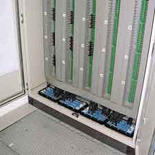
Electrical substation cabinets for control and switching and any other cabinets used inside or outside the substation should be sealed against environmental hazards that may disturb the functionality of sensitive electrical and electronic equipment.
Roxtec Seals HV Electricity Substations, Transmission & Distribution
Roxtec have a track record in providing reliable Substation Cable Sealing to UK DNO’s and overseas electricity authorities.
Typical applications include sealing cables into control rooms, service rooms and control boxes at the high or medium voltage electricity substation.
Roxtec H3 Triplex Seals prevent water ingress generating increased humidity leading to partial discharge and eventual loss of power supply into 11kV, 33kV and 132kV substations.
Roxtec cable seals provide sealing solutions, with spare capacity for future cables, to prevent water ingress, gas migration and rodent infestation from damaging substation electrical equipment and causing loss of power supply.
Pictured : Roxtec H3 Cable Seal For Medium Voltage 11kV 33kV Trefoil Cables
Thorne & Derrick
Thorne & Derrick are national distributors of LV, MV & HV Cable Installation, Jointing, Substation & Electrical Equipment – servicing businesses involved in cabling, jointing, substation, earthing, overhead line and electrical construction at LV, 11kV, 33kV, 66kV and EHV. Supplying a complete range of power cable accessories to support the installation and maintenance of low/medium and high voltage voltage power systems:
uploaded by Chris Dodds | Thorne & Derrick Sales Marketing Manager
article by Roxtec
Retrofitting a flooded substation
A flooded electrical substation. A run-down pump. And another switchgear failure.
Do you recognize the scenario?Would you like to avoid it?
Learn how to get it all right from the start.
Distribution network operators and maintenance contractors all over the world struggle against water and dust ingress in electrical assets such as substation basements and control rooms. Since humidity is often the cause of partial discharge activity, equipment damages, switchgear failures and costly power outages, they have a lot to win in keeping the basements dry. There are ways of sealing properly against water leakage through openings for cables and pipes using cable transits and thereby eliminate the risk.
Cable & Pipe Sealing Transits & Systems
1. Face the facts
To be honest, mastics, compounds and other traditional sealing products do not withstand the pressure of a high ground water table or the strain of the cable load. Neither do they seal between cables. Mastics may be cheap to buy, but the total cost of damages and outages actually makes them expensive. When the flood enters, you should call a provider of reliable cable sealing solutions.
2. Locate the leaks in the flooded substation
A professional sealing expert from Roxtec will meet you, survey the flooded site and establish an action plan. This specialist presents durable retrofit solutions for each opening, in line with requirements. Meanwhile, you will learn how to detect weak duct sealing methods – and to secure the openings before it is too late.
3. Get it all right
When you turn to experts, you get drawings, certificates and installation instructions and you often receive the seals within 48 hours. In addition, the experts provide onsite support and perform quality checks after installation. First class retrofit seals can be used in running water conditions and will still perform within 24 hours. Compare this to the normal curing time of ten days for mastics.
Established since 1985, T&D distribute the most extensive range of LV, MV & HV Cable Jointing, Terminating, Pulling & Installation Equipment – contact us today for a competitive quotation.