

Blog
Cable Pulling | Safe Pulling of Cables Using Motorised Pullers
January 16th, 2020
Cable Pulling | Safe Pulling of Cables Using Motorised Pullers
Pulling with motorised assistance
In most cases the cable is pulled with motorised assistance. During this procedure, forces of tension result, which, depending on the type of LV MV HV cable to be pulled, can reach double kN figures. Particular attention must therefore be paid to work safety.
Trained staff and faultless equipment which is regularly checked and maintained should be a matter of course in order to guarantee safe operation. Damaged pulling ropes or bent hooks should be removed and replaced with safe ones.
Pulling of the cable should occur with constant monitoring of the connected tension gauge.
Suddenly increasing tension levels may indicate that the cable is obstructed or has become caught in the cable duct. Operators must reduce the speed of the cable winch or stop it in order to identify the cause.
While the cable is being pulled it must be ensured that the cable is running over the installed deflector rolls. Instances of cable damage occurring as a result of edges, corners or stones, or vehicles driving over the cable, are to be avoided at all costs.
The complete cable pulling process should be recorded in a protocol and any anomalies or irregularities should be noted. The tension measurements should also be added.
Once cable pulling is complete, the run should, where possible, be inspected again.
The cable end caps should once more be checked to ensure that they are securely fixed and watertight and should only be opened in preparation for a connection or the fitting of cable sleeves.
Cable Pulling Protocol for Low & High Voltage Cables
The protocol of tension measurements, which contains readings of the tension that occurred during pulling in, is essential to demonstrate that pulling in has been carried out correctly. If such a protocol can not be provided or if too high tension has occurred, the cable manufacturer will indicate incorrect laying and suspend the guarantee for any resultant damage.
In all cases the laying instructions of the customer and the cable manufacturer are to be observed, especially the data referring to bending radius and tensile strength.
Caterpillar Tracks
Where there is sufficient space it is possible to use underground cable caterpillar tracks, which support the pulling of the cable by pushing it along with a motorised caterpillar track system. Versions with electric motor, hydraulic drive or internal combustion engine allow the use of an underground cable caterpillar track irrespective of location.
When pulling outdoor cables in cable pipe with narrow cross sections the use of cable lubricating grease should be considered. Static friction between the cable sheath and the pipe walls is minimised by the grease, which makes it easier to pull the cable into the pipe.

Press Release | Thorne & Derrick Appointed Approved Stockist for UK Leading Cable Pulling Equipment Manufacturer
Further Reading
- Cable Laying | The Importance of Cable Installation Instructions
- Cable Drums | Recommended Transport & Storage
- How to Prepare Cables To Avoid Cable Damages & Faults
- Cable Pulling | Safe Pulling of Cables Using Manual Laying
- Installation of Cable Sleeves | Jointing & Splicing Cables
- Installation of Rail Foot Cables
Cable Pulling Equipment
Thorne & Derrick distribute an extensive range of Cable Pulling & Laying Equipment to enable the safe installation of fibre and copper cables within the telecommunications industry. Safely installed cables reduces operational and maintenance requirements to the network and reduced service interruption to telecom cables, wires, ducts, cabinets and exchanges – products include cable spiking tools, conduit rods, cable lubricant, cable socks and rollers.

How to Prepare Cables To Avoid Cable Damages & Faults
January 16th, 2020
How to Prepare Cables To Avoid Cable Damages & Faults
Preparation of Cable & Run
A careful preparation of cable, cable drum and run can avoid a number of potential reasons for damages and faults.
Low & High Voltage Cables
Cables to be laid outdoors are usually delivered on large wooden or steel drums.
Manual laying of cables is not possible due to the excessive weight.
The cable drums are therefore placed in an uncoiling stand by crane or hydraulically. This stand can either be erected on a HGV trailer or separately, as seen in the picture on the right. The cable drum must have sufficient clearance from the ground and be able to turn freely.
The rolling direction marked on the drum must be observed.
Rolling against the rolling direction results in the loosening of the cable on the reel, which impedes uncoiling. The cable is always uncoiled at a tangent. A cable must NEVER be uncoiled over the flange. The resultant torsion can irreparably damage the cable.
This is equally true for indoor cables coiled on small and light plywood reels and for ring-wound goods.
Before laying the cable, check whether the cable ends have been correctly capped and are undamaged. Missing or improperly glued caps can lead to moisture penetration during transport or laying. The same applies to any damage to the external sheath or insufficient pressure in the case of pressurised telephone cables. Moisture in the cable generally causes deterioration in the insulation resistance and the operational capacity.
A visibly damaged cable must therefore not be wound without closer inspection and clarification of the causes.
Due to their sometimes excessive weight, outdoor cables usually can not be wound by hand. Appropriate winding aids, available in diverse motorised versions, should therefore be used. Make sure that it is possible to provide evidence of the pulling in forces (tension protocol)!
There are numerous possibilities for fastening a pulling rope to a cable and this should be chosen to suit the cable type. For telecommunications cables we recommend conductor pulling with a cable pulling head.
In our example we have used a cable sock. The fastening of the pulling rope to the cable must be undertaken with care to avoid ‘losing’ the cable on the way. Corners and edges at the cross-over point from cable to rope are to be avoided otherwise the cable can easily become stuck on ledges or bumps underground. Guide swivels should be used between the cable sock and pulling rope.
The choice of the correct cable grip is dependent on the diameter of the cable.
Press Release | Thorne & Derrick Appointed Approved Stockist for UK Leading Cable Pulling Equipment Manufacturer
The Cable Run
The LV HV cable run is checked before laying the cable.
- Have the minimum bending radii prescribed by the cable manufacturer been followed during laying? If necessary the run must be modified
- Are the trench, shaft, cable duct or cable pipe free of foreign bodies, sharp edges or corners and dampness or moisture?
Inspection and examination of the run prior to laying are essential. A visual check, however, is only possible for open trenches or shafts. A brush pulled through the pipe, with monitoring of any potential tension, also permits an assessment of any inaccessible areas.
If the duct brush becomes stuck in the pipe or if there is a temporary but significant increase in tension, this indicates dirty sections or badly fitting pipe connections.
Dolly-mounted cameras can help in the inspection of a pipe or channel. Thanks to modern technology the inside of the pipe can be viewed live on screen. An accompanying meter counter gives the exact position of potential trouble spots.
Cables which are led through shafts or around corners must always run over deflector rolls. This is an effective way to avoid mechanical damage to the cable sheath.
In order to achieve this some corners require a considerable measure of imagination and clever construction. It is therefore essential to have a plentiful supply of deflector rolls and to choose them correctly.
When pulling horizontally rollers should also always be placed on the ground. The cable must not drag along the ground. An even pulling of the cable with the minimum possible resistance ensures quick and faultless laying.

Cables which are led through shafts or around corners must always run over deflector rolls. This is an effective way to avoid mechanical damage to the cable sheath.

Dolly mounted cameras can help in the inspection of a pipe or channel
Further Reading
- Cable Laying | The Importance of Cable Installation Instructions
- Cable Drums | Recommended Transport & Storage
- Cable Pulling | Safe Pulling of Cables Using Motorised Pullers
- Cable Pulling | Safe Pulling of Cables Using Manual Laying
- Installation of Cable Sleeves | Jointing & Splicing Cables
- Installation of Rail Foot Cables
Cable Pulling Equipment
Thorne & Derrick distribute an extensive range of Cable Pulling & Laying Equipment to enable the safe installation of fibre and copper cables within the telecommunications industry. Safely installed cables reduces operational and maintenance requirements to the network and reduced service interruption to telecom cables, wires, ducts, cabinets and exchanges – products include cable spiking tools, conduit rods, cable lubricant, cable socks and rollers.
Cable Drums | Recommended Transport & Storage
January 15th, 2020
Cable Drums
Cable Drums
Even if cable and cable drum look very strong, there are certain rules to follow to avoid damage of the cable and an accompanying impairment of mechanical and electrical characteristics for LV MV HV cables.
Transport & Storage of Cable Drums
It is possible to store cable drums outdoors.
When storage has occurred in heated rooms, a minimum 24-hour acclimatisation period must be observed before installation (possible condensation build-up in the cable!).
For outdoor storage the ground must be even and clean.
Stones or bumps in the ground should be removed or smoothed out.
Damage to the wound goods/cable should be avoided at all costs.
Cables should be secured against accidental rolling away. Under no circumstances should the drum flange of neighbouring cables touch any wound goods.
Cable drums should always be stored and transported standing on both flanges.
They should not be pushed along the ground standing on the flanges. It is possible that the strength of the cable drum would then no longer be guaranteed.
Observe the rolling direction. The arrow printed on the drum flange indicates the rolling direction so that the wound goods do not become loose.
Always uncoil the cable at a tangent, never over the flange, since the torsion thus resulting would damage the cable and laying would not be possible.
Cable Ends
Finally it remains for us to point out the necessity of having faultless cable ends.
Pressure-tight and impermeable cable ends are particularly essential for cables which are not longitudinally water-proof, as well as for cables which are insulated with paper, cellular-PE and foam-skin-PE.
Carelessness in this area can lead to moisture penetration which is accompanied by a drastic deterioration in the electrical transmission rate.
Power failures and expensive replacement work are the result. Pressure-tight and impermeable cable ends can be achieved, for example, through the use of synthetic sealing resin, compressed air sealing stoppers or cable end caps.
Press Release | Thorne & Derrick Appointed Approved Stockist for UK Leading Cable Pulling Equipment Manufacturer
Further Reading
- Cable Laying | The Importance of Cable Installation Instructions
- How to Prepare Cables To Avoid Cable Damages & Faults
- Cable Pulling | Safe Pulling of Cables Using Motorised Pullers
- Cable Pulling | Safe Pulling of Cables Using Manual Laying
- Installation of Cable Sleeves | Jointing & Splicing Cables
- Installation of Rail Foot Cables
Cable Pulling Equipment
Thorne & Derrick distribute an extensive range of Cable Pulling & Laying Equipment to enable the safe installation of fibre and copper cables within the telecommunications industry. Safely installed cables reduces operational and maintenance requirements to the network and reduced service interruption to telecom cables, wires, ducts, cabinets and exchanges – products include cable spiking tools, conduit rods, cable lubricant, cable socks and rollers.
5 Arc Flash Risks for Solar Industry Personnel
January 15th, 2020
Arc Flash Risks And Dangers
Introduction to Arc Flash
The proliferation of solar panels used in industrial and commercial building is a reflection of the decreasing cost of the photovoltaic modules and the increasing interest in renewable energy sources. The widespread use of photovoltaic systems increases the risk of exposure to electrical safety hazards that are inherently associated to nonlinear power sources.
It is a well-known fact that the standard protection devices are inefficient in detecting short circuit faults in photovoltaic systems. In addition, it is now recognized that the maximum incident energy deployed by a DC arc flash in a photovoltaic system is higher, and in many instances significantly higher, than those estimated by using the guidelines given by the NFPA 70E and the CSA Z462-12 standards.
Use of the existing guidelines can result in personnel being exposed to much higher safety risks than previously thought – here we consider 5 Arc Flash risks prevalent in the solar industry.
This article has been republished with the kind permission of Ben Cass from SKANWEAR.
Arc Flash In the solar Industry
With government plans to significantly increase the amount of energy generated through sustainable sources well underway, and with solar panels recognised as one of the most accessible ways for homeowners to make the switch, the solar industry is booming.
However, this is also an industry that comes with notable risks, particularly in terms of arc flash hazards.
The risk is so pronounced within the solar industry in particular due to the DC circuits found within typical PV installations, which can both generate and sustain arcs.
DC circuits present a greater challenge than AC circuits due to the constant-current source rather than constant voltage, which makes calculating arc energies difficult.
So just what are some of the biggest Arc Flash risks for Solar Industry Personnel?
The design systems of PV installations pose one of the greatest risks as there are many types of intermittent connection that the system can create which may then generate series Arc.
For example, anything from compression wire connections to soldered joints to the actual connectors that attach to the PV modules are all capable of creating intermittent connections and generating series arc. Quite simply, Arc Flash can occur remarkably easily within the solar industry, resulting in greater risk for solar personnel.

At midday on 30 June 2018, solar power supplied 30 per cent of the UK’s electricity (Shutterstock). Via Independent.
News: The largest solar power plant ever proposed in the UK will be reviewed by the Secretary of State within the next six months. Cleve Hill solar farm will occupy the north coast of Kent and, if built, provide up to 350MW (megawatts) of generating capacity.
Arc Flash Heat
The types of Arc Flash that can be generated within the solar industry are another major risk. With arcs capable of reaching more than 3000 degrees Celsius in temperature, these arcs not only cause fires but can also melt materials such as glass and metals including copper and aluminium. This can subsequently ignite any combustible materials and items in the surrounding area. In the solar industry, it is not only the direct risks of arc flash that must be considered but also the many possible indirect risks, too.
An Arc Flash event can expel large amounts of deadly energy. The arc causes an ionization of the air, and arc flash temperatures can reach as high as 35,000 degrees Fahrenheit. This is hotter than the surface of the sun.
Injury and Fatality of Arc Flash

Arc Flash Risks
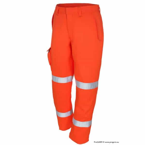
With the possibility of fire (in recent years there have been notable instances in the UK, USA, and Australia of PC installations causing fires along with significant damage to both domestic and commercial properties) and molten metal, injury and even fatality is a major risk for solar industry personnel. The best way to mitigate this risk is by wearing the correct Arc Protective Clothing equipment for the environment and identified hazards.
Dedicated arc flash PPE can minimise injury when worn correctly.
System Maintenance
Maintenance of equipment is undoubtedly one of the most effective ways to quickly identify system faults and reduce the chance of arc flash. However, due to the nature of PV installations, adequate system maintenance can be tricky, and a lack of thorough upkeep poses one of the greatest risks to solar industry personnel. With combiner boxes generally being located at a distance from each other, proper maintenance can involve disconnecting entire sections of the system at a time.
Required Action
Perhaps the greatest risk of all is the risk that solar personnel take inappropriate action when arc flash is determined to be most likely. With DC circuits, there are different Types of Arc Flash that can occur, with each requiring different action to be taken. With series arc, for example, a shutdown of power and significant reduction in circuit flow is needed. With parallel arc, however, conductors must be shorted simultaneously resulting in zero array voltage. Understanding system management is the key to safety.
If you are working on live Solar Panels there is a possibility an Arc Flash could happen.
Make sure you and your team are working safely on live electricity with Arc Flash and Flame Resistant Clothing, see our full collection here.

Solar Fires – DC Arc Faults. Arc flash is a dangerous risk among those in the power industry. Arc flash is an electrical breakdown of the resistance of air that results in an electric arc, which can occur where there is sufficient voltage in an electrical system and a path to ground or lower voltage.
THORNE & DERRICK SPECIALIST ELECTRICAL DISTRIBUTOR

The LV HV Specialists
Thorne & Derrick distribute the most extensive range of Cable Installation & Electrical Distribution Equipmentto the renewable energy sector – we service UK and international clients working on underground cables, overhead lines, substations and electrical construction at 11kV and up to and EHV transmission and distribution voltages.
- Key 11kV Products: MV-HV Cable Joints & Terminations, Cable Cleats, Duct Seals, Cable Transits, Underground Cable Protection, Copper Earth Tapes, Cable Jointing Tools, Feeder Pillars, Cable Ducting, Earthing & Lightning Protection, Electrical Safety, Cable Glands, Arc Flash Protection & Fusegear.
- Distributors for: 3M Cold Shrink, ABB, Alroc, Band-It, Catu, Cembre, Centriforce, CMP, Elastimold, Ellis Patents, Emtelle, Furse, Lucy Zodion, Nexans Euromold, Pfisterer, Polypipe, Prysmian, Roxtec.

LV– Low Voltage Cable Joints, Glands, Cleats, Lugs & Accessories (1000 Volts)

MV HV – Medium & High Voltage Cable Joints, Terminations & Connectors (11kV 33kV EHV)

Cable Laying – Underground Cable Covers, Ducting, Seals & Cable Pulling Equipment

T&D, CATU Electrical Safety & Arc Flash Protection Specialists for SAP’s, Linesmen, Jointers & Electrical Engineers – Largest UK Stockist
Arc Flash Learning & Resources

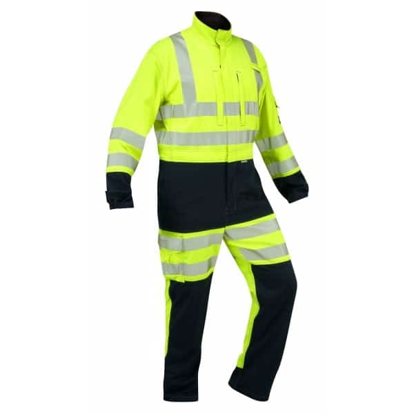
Thorne and Derrick are proud to be distributors of ProGARM arc flash coveralls and protection.
We can help – should you require arc flash calculators or advice on the type of clothing and protection available please do not hesitate to contact us.


Cable Laying | The Importance of Cable Installation Instructions
January 14th, 2020
Cable Laying | The Importance of Cable Installation Instructions
Cable Laying
Usually the only people who take any notice of cables and wires are those who work with them. Most of us use the telephone, watch television or surf the Internet without thinking about how the underlying infrastructure, the network of cables, has been assembled.
Cables are rarely heeded; they are ‘simply there’.
General knowledge about cables is equally lacking. Very few people know what high technology is wrapped up in the inconspicuous black, grey or coloured wires. Indoor cables in particular are subjected to heavy handling by the user: office chairs are rolled over telephone connection wires, computer patch cables are trodden on by people or nibbled by their amusing pets.
Outdoor cables are affected by huge differences in temperature and high bending and pulling forces while they are being laid. The thicker the cable the stronger it may appear. However thick as well as thin wires are subject to the same physical conditions and limits.
The following Blogs aim to raise awareness about cables and explain terms such as bending radius, temperature ranges or permissible tension. Furthermore you will find instructions and tips for correct and safe installation.
Parameters
Initially people have the idea, ‘We should/ must modernise or expand our network’.
An engineering consultancy is hired to transform the idea into a feasible plan.
Basic conditions and objectives are decided together with the customer. At the same time many technical parameters must also be considered along with the questions related to infrastructure.
During the realisation phase for the plans numerous trades work closely together. One of these is concerned with the laying of the physical network of wires or cables.
The installation company responsible for laying the cables must heed the following parameters:
- temperature range of the cable,
- bending radius of the cable,
- maximum tension of the cable,
- weight of the cable as well as
- storage and cutting.
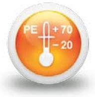
Temperature Range
The temperature range of the cable is of great importance for both the user and fitter.
After all the cable is meant to function equally well in cold and hot temperatures. It is particularly during the fitting process that powerful mechanical forces act on the cable. The plastic used serves as the limiting element for the possible temperature range.
At overly warm temperatures the plastic becomes very soft and can change into a thermoplastic state (up to melting point), which causes irreversible changes in the cable.
At very cold temperatures, however, the material stiffens and becomes hard and inflexible. Here, too, irreparable damage can occur.
Tears in the sheath allow dampness and moisture in and impair the transmission rate.
Details about the permissible temperature range during laying and use (following successful fitting) can be found in the information sheets of the cable manufacturer. Since the mechanical strain on the cable in its laid form is significantly less, the permissible temperature range is greater than the range valid for the installation period.
The VDE 0816 gives the following values:
During Cable Laying
PE-sheath, from -20 ° C to + 50 ° C
PVC-sheath, from – 5 ° C to + 50 ° C
Before & After Cable Laying
PE-sheath, from -20 ° C to + 70 ° C
PVC-sheath, from – 5 ° C to + 70 ° C
Cable Bending Radius
Regarding the bending radius we distinguish between multiple and single bending (shaping into the final position). Multiple bending occurs mainly during the laying process.
Cables are laid under tension around deflector rolls. The particular stress of multiple bending lies in the alternating stress on the materials, which can be stretched several times as well as compressed during the laying process. To prevent permanent damage there are prescribed minimum bending radii of, for example, 10 x cable external diameter for multiple bending.
The stress on the material during final bending is not characterised by alternating stress.
The cable is bent into form a final time and stays in this position for the duration of its use. The minimum bending radius in this case is, for example, 7.5 x cable external diameter. During final bending the cable can, therefore, be bent more tightly.
Exact minimum bending radii for specific cables can be found in the information sheets of the cable manufacturer.
Tension
During laying of the cable particular attention must be paid to the maximum possible tension. The cable is very quickly damaged by the use of too much force and must then be replaced. The maximum possible tension depends in the first place on the overall cross section and the tensile strength of the conducting materials used.
For cables with steel tape or copper wire spiral armouring it is the internal copper conductors alone which determine the maximum tension! The armouring has no influence on the maximum tension or can possibly reduce it through additional weight.
For armouring with steel or steel profile wires, however, the tension is determined solely by the steel and steel profile wires.
Cable Weight
The cable weight of larger cable dimensions can take weights of up to more than 9 t/km (without the reel!).
Storage & Cable Cutting
Cables for delivery as well as cut cables must generally be protected against moisture penetration. This best occurs through the use of shrink caps with fusible glue. Loose-fitting caps or temporary measures with plastic adhesive tape are not watertight and are unsuitable.
Moisture penetration leads to corrosion and deterioration of the transmission rate.
If two cable ends are to be connected with a sleeve, this must take place immediately and with protection against moisture and rain. For the period of the sleeve installation an installation tent must be erected.
Press Release | Thorne & Derrick Appointed Approved Stockist for UK Leading Cable Pulling Equipment Manufacturer
Further Reading
- Cable Drums | Recommended Transport & Storage
- How to Prepare Cables To Avoid Cable Damages & Faults
- Cable Pulling | Safe Pulling of Cables Using Motorised Pullers
- Cable Pulling | Safe Pulling of Cables Using Manual Laying
- Installation of Cable Sleeves | Jointing & Splicing Cables
- Installation of Rail Foot Cables
Cable Pulling Equipment
Thorne & Derrick distribute an extensive range of Cable Pulling & Laying Equipment to enable the safe installation of fibre and copper cables within the telecommunications industry. Safely installed cables reduces operational and maintenance requirements to the network and reduced service interruption to telecom cables, wires, ducts, cabinets and exchanges – products include cable spiking tools, conduit rods, cable lubricant, cable socks and rollers.
Further Reading | Cable Drum Handling & Laying Cables | A Guide from Nexans
