

Blog
Reyrolle LMV Switchgear
October 28th, 2019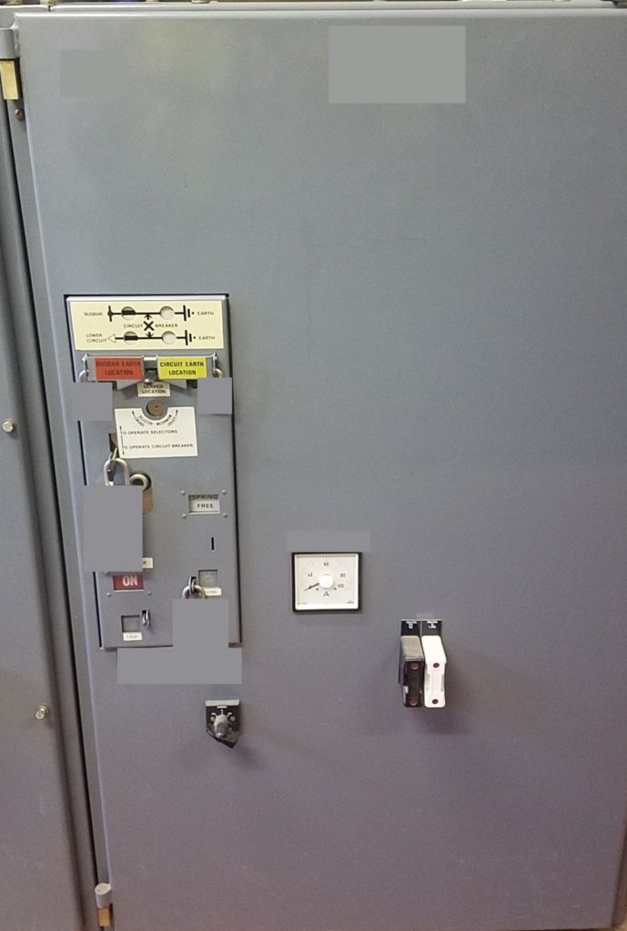
Reyrolle LMV Switchgear
Credit: Mikolaj Kukawski | Customer Networks Manager at ESM Power Ltd
Featured Manufacturer: Reyrolle
MV HV Switchgear
Mikolaj is an experienced Private HV Networks Manager with a demonstrated history of working in the utilities and  medium/high voltage (MV HV) sectors of industry.
Skilled in MV HV Electrical Power Distribution Systems operation, maintenance and asset replacement. Strong operations professional with SAP experience up to 132kV for both private and DNO networks.
ESM Power design, deliver and manage LV MV HV electrical networks safely, securely and economically – this includes ICP and DNO connections at LV, 11kV, 33kV and 132kV.
➡ See complete Switchgear MV HV Album.

Switchgear MV HV | Thorne & Derrick distribute Nexans Euromold, 3M Electrical, PFISTERER Connex, Prysmian and Shrink Polymer Systems ranges of Joints, Terminations & Connectors to enable the installation and maintenance of electrical switchgear, transformers and substations.
T&D supply Cables, Accessories & Electrical Products for Low Voltage (LV 230V to 1000V), Medium Voltage (MV 3.3kV/11kV to 33kV) and High Voltage (HV 33kV to 132kV) networks.
JOINTERS BLOG
Subscribe now to our POWER NEWSLETTER– a monthly email circulation packed with news, projects, videos, technical tips, training information, promotions, webinars, career opportunities and white papers.
Includes access to our popular JOINTERS BLOG with contributions from utility professionals, linesmen and cable jointers working on MV HV EHV cables and overhead lines typically at 11kV, 33kV, 66kV and up to 132kV.
15,000+ Subscribers. ➡

Joints | Terminations | Connectors | Cables & Accessories LV MV HV
Power Cables Courses | Ageing & Asset Management with DNV GL 2019 2020
October 28th, 2019
Power Cables Courses
Technology tRAINING
Permission by: Irene Heunks – Manager Energy Academy
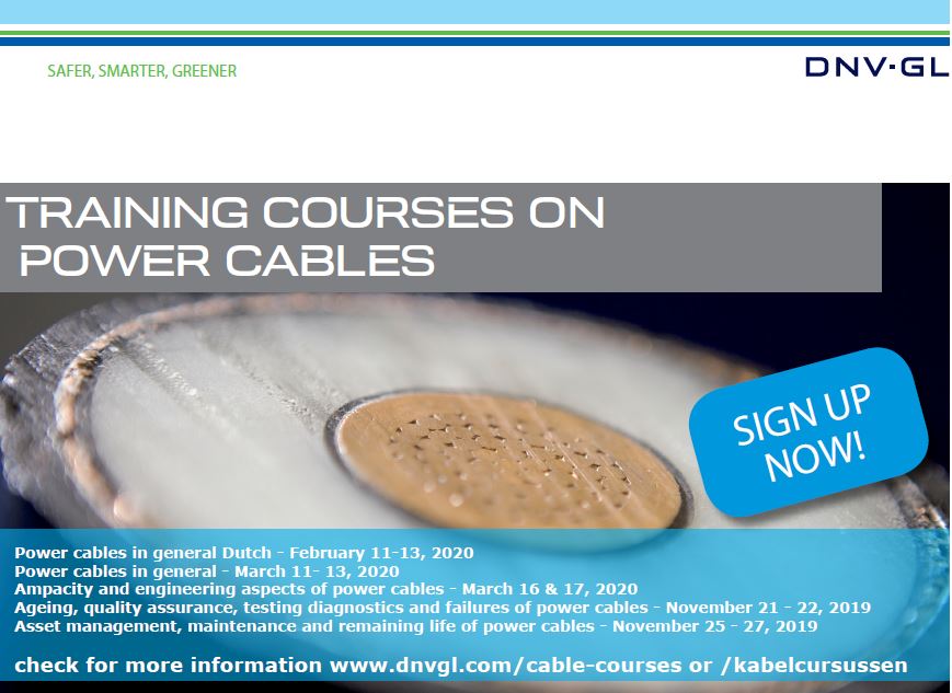
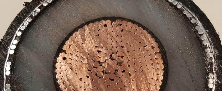
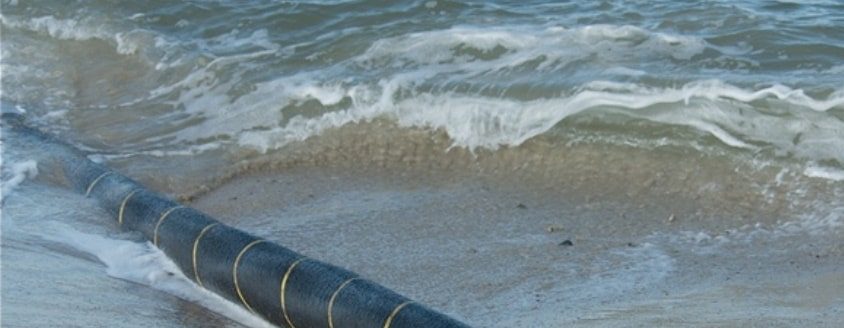
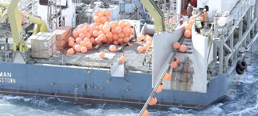
Thorne & Derrick are working with DNV GL to promote their power cables courses and training services.
Drawing on its expertise in the field of power cables, DNV GL has developed dedicated training courses to transfer knowledge and link theory to day-to-day operations.
➡ Sign up now for the Power Cables Courses –2019 and 2020 – Arnhem, the Netherlands. Ageing and Asset management power cables are planned in November.
TO REGISTER: go to the DNV GL website, and download the registration form for your chosen course. Send the filled registration form to [email protected]
DNV GL’s Energy Academy offers a series of courses, that consist of a general three-day course with a complete overview of all (basic) principles and practice of using underground power cables and several in-depth courses, amongst other the following two upcoming courses:
- Ageing, QA, testing, diagnostics and failures of power cables (Nov 21-22, 2019)
- Asset management, maintenance and remaining life of power cables (Nov 25-27, 2019)
Find out more below about each of the coursed running in November 2019, as well as additional and future planned power cables courses.


About DNV GL
“Since 1864, our purpose has been to safeguard life, property and the environment.
DNV GL is a global quality assurance and risk management company. Driven by our purpose of safeguarding life, property and the environment, we enable our customers to advance the safety and sustainability of their business.
Each day, you will find us at work with over 100,000 customers, in more than 100 countries, building the invisible infrastructure of trust. We are the leading provider of risk management and quality assurance services to the maritime, oil and gas, and power and renewables industries. We are also global leaders in certifying management systems of companies across all types of industries including healthcare, food and beverage and aerospace.”

JOINTERS BLOG
Subscribe now to our POWER NEWSLETTER– a monthly email circulation packed with news, projects, videos, technical tips, training information, promotions, webinars, career opportunities and white papers.
Includes access to our popular JOINTERS BLOG with contributions from utility professionals, linesmen and cable jointers working on MV HV EHV cables and overhead lines typically at 11kV, 33kV, 66kV and up to 132kV.
15,000+ Subscribers. ➡
THORNE & DERRICK
T&D are Specialist Distributors to UK Distribution Network Operators (DNO’s), NERS Registered Service Providers, ICP’s and HV Jointing Contractors of an extensive range of LV, MV & HV Jointing, Earthing, Substation & Electrical Eqpt – this includes 11kV/33kV/66kV cable joints, terminations and connectors for both DNO and private network applications.
Specialists Distributors of Cable Sealing Systems from leading manufacturers including: Hauff Technik | Roxtec | CSD | Filoseal
Contact our UK Power Team for competitive quotations, fast delivery from stock and technical support or training on all LV-HV products.
Key Product Categories: Duct Seals | Cable Cleats | Cable Glands | Electrical Safety | Arc Flash Protection | Cable Jointing Tools | Cable Pulling | Earthing | Feeder Pillars | Cable Joints LV | Joints & Terminations MV HV

Lightning | An Introduction To Lightning Protection | Networks, Strategy & Systems | Part Two
October 23rd, 2019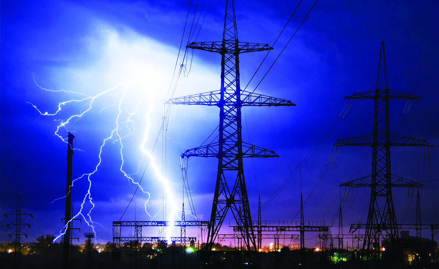
An Introduction To Lightning Protection
-
uploaded by Chris Dodds - Thorne & Derrick Sales & Marketing Manager
Earthing
Lightning Protection
AN Wallis
In the second part of the series AN Wallis gives an introduction to lightning protection focusing on systems, strategies and earth terminations and networks.
➡ Earthing | An Introduction To Earthing & Earthing Designs | Part One
Structural Lightning Protection
Structural Lightning Protection systems are installed to minimise the risk of damage to the external & internal parts of the structure, including the electrical and electronic equipment from a lightning strike and reducing the risk of injury to humans by safely discharging the high voltage to the earth system.
The external lightning protection attracts the lightning discharge and conducts it safely to earth and the internal lightning protection, with use of transient surge protectors, minimises the damage to sensitive equipment and bonding of conductive services ensure a safe path to earth.
A complete Lightning Protection System (LPS) can only be achieved when both safety measures of Internal & External LPS are employed to the structure based on the Risk Assessment.

Lightning Protection System (LPS) JG253 – In-Situ
Lightning Protection Strategy
The normal strategy in achieving protection is to capture the lightning at a preferred point by the use of air terminations and conducting it via low impedance down conductors and earth electrodes to a low resistance earth of less than ten ohms.
Air terminations and down conductors are spaced at regular intervals to form a mesh of conductors around the perimeter of the building and roof, known as a Faraday cage, and are joined together by specially produced damps and fixings or welding.
Lightning Protection System Design Considerations
A LPS is designed according to geographical location, local terrain, soil conditions, size and height of building, type of material used in construction, type of material stored in the building, use of building and is based on established standards for risk assessment.
The Risk Assessment needs to be carried out prior to the design of the structural LPS to determine the Class of LPL required based on the IEC / BS EN 62305 standards or internationally accepted standards.
Air Termination Networks
Based on the determined Class of LPL conductor spacing’s can be selected as identified below:
| Class of LPS | Roof Mesh Conductors W (Width – Metres) | Rolling Sphere Radius r (Radius – Metres) | Protection Angle a (Degree) | Down Conductor Spacing (Metres) |
| I | 5 x 5 | 20 | Refer to chart | 10 |
| II | 10 x10 | 30 | 15 | |
| III | 15 x 15 | 45 | 15 | |
| IV | 20 x 20 | 60 | 20 |
To calculate the areas of protection the Rolling Sphere technique can be employed. The zone of protection determined by the methods requires protection through the Roof Mesh method and Protective Angle Methods.
Roof Mesh Method — Simple and direct implementation of conductor spacing’s based on the Class of LPS, e.g. Class I LPS — Roof conductors are to be spaced in a grid of 5 x 5 metres throughout the flat roof plane.
The Protective Angle Method is based on the relativity between the height of protection required to the prescribed angle of protection in conjecture with the height to be protected which can be obtained from the chart below. Key areas or strike points need to be determined before employing the protection measure.

Class of LPS Graph
Down Conductors
Down conductor spacing has to be in accordance with the Class of LPS which is determined and to be adopted based on the table. E.g. Class I LPS — Down conductors to be spaced at every 10 metres of the structure around the periphery of the structure.
The spacing should be carried out as evenly as possible on the periphery starting at the corners and at the shortest distance to earth.
Sufficient separation distance ‘s’ need to be maintained when down conductors are placed in overhangs and care to be taken to avoid re-entrant loops.
Earth Terminations & Networks
The information contained in this section is primarily for LPS earthing.
For Earth Termination systems two basic types of earth electrode arrangements are applied. Type A earthing arrangement is suitable for low structures and existing structures. Type B earthing arrangement is usually followed throughout.
Each down conductor needs to be connected to an earth electrode to form the earthing with a minimum of two. The minimum length of earth rods that are required to be driven into ground is 2.4 metres. Earthing system contains of horizontal earth electrodes and vertical earth electrodes. Earth rods may need an earth inspection housing for periodic testing of earth resistance.
Resistance to Earth
To maintain a safe earth system, it is recommended that the earth rods to ground resistance values are less than 10 ohms. Earth resistance values are measured at low frequency.
A single earth rod may not achieve the required resistance figure and several may need to be fitted to achieve this; their combined resistance is proportional to the reciprocal of the individual rod resistances to earth.
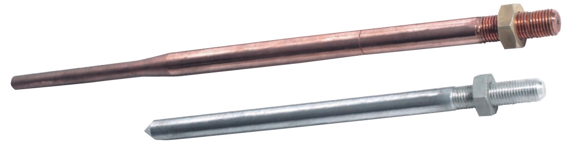
Earth Rods
This rule holds true as long as each rod is situated outside the resistance area of any other. To ensure this is the case, it is generally accepted that the minimum spacing between rods should not be less than their driven length.
The expected number of rods required to obtain a particular resistance value, e.g. ten ohms, can be roughly calculated.
To do this the soil resistivity needs to be taken into consideration. A soil resistivity test will need to be performed.
There are several methods used to obtain a lower resistance value:
- More rods can be driven. Rods can be driven deeper
- Rods of a larger diameter can be used
- Ring conductors connecting rods together underground can be used
- Where deep driving is not possible shorter rods with a larger diameter can be used; copper earth mats and earth plates can be used in place of earth rods
- A “crows foot” configuration can be used where a parallel connection is not possible
Where high resistance soil conditions are a problem soil conditioning agents can be used to backfill rod holes. Conductive concrete can be used to backfill an earth mat. Both effectively increase an electrodes cross sectional area and therefore reduce its resistance to earth.
The international standards also specify the recommended materials used for all earthing conductors and their dimensions.
Equipotential Bonding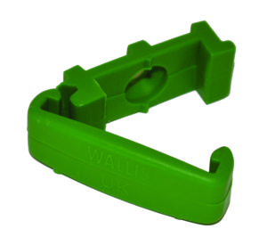
It is common practice to use the buildings natural structural steelwork and bonding it to the LPS to further improve its ability to conduct lightning and fault currents to earth; prior permission may be required.
Joints
Joints should be mechanically effective, all joints other than welded ones are a potential discontinuity, and care should be taken to ensure contact surfaces are clean and that fixing clamps are tight and well protected from corrosion, which can occur if dissimilar metals are joined. Ideally there should be as few joints as possible in an LPS design.
Maintenance & Life of an LPS
It is important to properly maintain an LPS to ensure it retains its ability to conduct the same current carrying capacity as it did when it was originally installed. Earth rod resistances should be regularly checked.
Corrosion and fault currents can cause high resistance joints leading to overheating. However, if an LPS is correctly installed and maintained it should last for many years.
The information contained in this section is intended as a guide and should not be used to perform designs. AN Wallis does not accept responsibility for errors or omissions. Detailed information on LPS design is contained in internationally recognised European and British LPS standards.
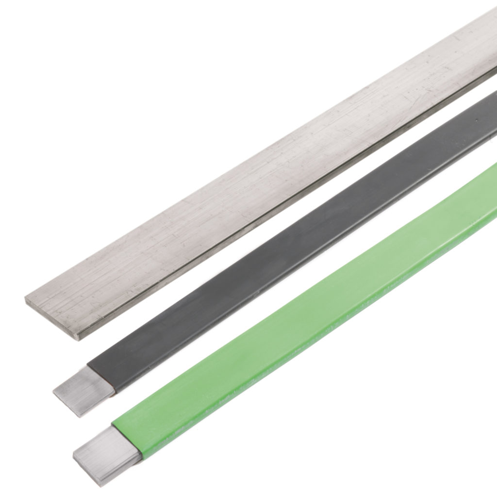

Earthing – Copper Earth Tapes | Bars | Clamps | Rods

THORNE & DERRICK
T&D are Specialist Distributors to UK Distribution Network Operators (DNO’s), NERS Registered Service Providers, ICP’s and HV Jointing Contractors of an extensive range of LV, MV & HV Jointing, Earthing, Substation & Electrical Eqpt – this includes 11kV/33kV/66kV cable joints, terminations and connectors for both DNO and private network applications.
Contact our UK Power Team for competitive quotations, fast delivery from stock and technical support or training on all LV-HV products.
Key Product Categories: Duct Seals | Cable Cleats | Cable Glands | Electrical Safety | Arc Flash Protection | Cable Jointing Tools | Cable Pulling | Earthing | Feeder Pillars | Cable Joints LV | Joints & Terminations MV HV
Nexans NX600 Alsecure Cable : Fire Resistant, Low Smoke & Halogen Free Cables
October 22nd, 2019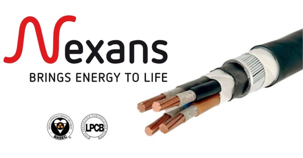
Nexans NX600 Alsecure Cable – Fire Resistant, Low Smoke & Halogen Free Cables
-
uploaded by Chris Dodds | Thorne & Derrick Sales Marketing Manager
Low Voltage Fire Resistant Power Cable
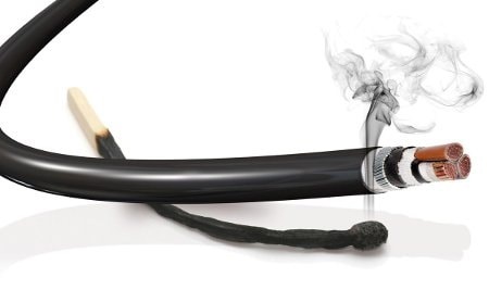
Nexans Alsecure NX600 fire resistant power cable is ideal for fire safety engineering systems in large multi-storey and complex buildings.
Nexans NX600 is a low smoke, halogen free and fire resistant cable which is designed to meet the requirements of the BS8491 fire test which simulates direct impact and also the effects of a high pressure water hose along with a continuous flame.
BS8491 is the British Standard regulating the method for assessment of fire integrity of large diameter power cables for use as components for smoke and heat control systems and certain other active fire safety systems.
The cable test incorporates direct fire attack, mechanical attack and water spray, over a variable time up to two hours. Several cable makers have produced enhanced fire resistant cables to meet this requirement.
Overcoming Fire Safety Cable Challenges
The increased scale and complexity of building design and architecture has made safe evacuation of the public during a fire evermore complicated.
The compounds and materials used in cable construction further complicate evacuation.
Traditional cables propagate flames and release hazardous fumes when they burn, this relates especially to halogenated PVC sheathed cables.
Fumes released during a fire can be more dangerous to human life than the flames themselves. The gases cause drowsiness, affect breathing and eventually cause death. For this reason, some installations require cables which will release low levels of smoke which is halogen free, and therefore non-toxic to humans.
Nexans Alsecure NX600 fire resistant cable is approved for 30, 60 and 120 minutes applications as detailed in BS8519 (Selection and installation of fire-resistant power and control cable systems for life safety and fire-fighting applications) and can be used in a vast variety of systems in building such as fire-fighting and evacuation lifts, sprinkler systems and wet riser pumps.
The Nexans fire resistant cable is also approved by both LPCB and BASEC to meet the requirements of BS7846-F120 to maintain circuit integrity in the event of a fire.
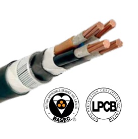
Nexan’s NX600 cable is available for sizes up to and including 35sqmm with circular conductors or 50-330sqmm with sector shaped conductors.
The steel wire armour (SWA) is a single layer of galvanised steel wires and the cores are identified by colours and covered with an extruded layer of polymeric compound.
NX600 Alsecure is specified for use in stadia, airports, hospitals, universities, hi-rise offices, residential and public building.
In the rail industry, fire resistant cables provide low voltage power distribution in and around train stations and security systems (video, ventilation, breakdown, emergency lighting).

Fire Resistant, Low Smoke & Halogen Free Cables
Nexans NX600 Alsecure Cable
Features & Benefits
| Standards | |
| Fire Resistance | BS 8491 120 min |
| Flame Propagation | BS EN 50266-2-4, IEC 60332-3-24 |
| Smoke Emission | BS EN 61034 |
| Design | BS 7846 |
| Certification | Certified by BASEC and LPCB |
| Characteristics | |
| Conductor Material | Copper |
| Conductor Flexibility | Standard Class 2 |
| Cable Insulation | XLPE & Mica Tape |
| Cable Outer Sheath | LSF |
| Colour | Black |
| Cable Inner Sheath | Halogen Free Compound |
| Rated Voltage Uo/U (Um) | 0.6/1kV |
| Minimum Installation Temperature | 0ºC |
| Maximum Operating Temperature | 90ºC |
| Short-Circuit Maximum Conductor Temperature | 250ºC |
| Fire Resistant | BS 8491-120 |
| Flame Retardant | IEC 60332-3 Cat.C |
Nexans NX600 Alsecure Cable – Product Range
| 3 Core Cable | |||||||
| Cross Section sqmm | Approx Insulation Thickness mm | Nominal Armour Wire Diameter | Approx Sheath Thickness mm | Approx Overall Diameter mm | Approx Cable Weight kg / km | Max Conductor Resistance at 20ºC | Min Bend Radius |
| 4 | 0.7 | 1.25 | 1.4 | 20.0 | 520 | 4.61 | 6D |
| 6 | 0.7 | 1.25 | 1.4 | 20.0 | 600 | 3.08 | 6D |
| 10 | 0.7 | 1.25 | 1.5 | 20.0 | 910 | 1.83 | 6D |
| 16 | 0.7 | 1.25 | 1.6 | 22.0 | 1150 | 1.15 | 6D |
| 25 | 0.9 | 1.6 | 1.7 | 26.0 | 1650 | 0.727 | 6D |
| 35 | 0.9 | 1.6 | 1.8 | 28.0 | 1850 | 0.524 | 6D |
| 50 | 1.0 | 1.6 | 1.8 | 31.0 | 2500 | 0.387 | 8D |
| 70 | 1.1 | 1.6 | 1.9 | 34.0 | 3100 | 0.268 | 8D |
| 95 | 1.1 | 2 | 2.1 | 39.0 | 4450 | 0.193 | 8D |
| 120 | 1.2 | 2 | 2.2 | 42.0 | 5250 | 0.153 | 8D |
| 150 | 1.4 | 2.5 | 2.3 | 47.0 | 6650 | 0.124 | 8D |
| 185 | 1.6 | 2.5 | 2.4 | 51.0 | 8050 | 0.0991 | 8D |
| 240 | 1.7 | 2.5 | 2.6 | 56.5 | 10050 | 0.0754 | 8D |
| 300 | 1.8 | 2.5 | 2.7 | 62.0 | 12150 | 0.0601 | 8D |
| 4 Core Cable | |||||||
| Cross Section sqmm | Approx Insulation Thickness mm | Nominal Armour Wire Diameter | Approx Sheath Thickness mm | Approx Overall Diameter mm | Approx Cable Weight kg / km | Max Conductor Resistance at 20ºC | Min Bend Radius |
| 4 | 0.7 | 1.25 | 1.4 | 20.0 | 610 | 4.61 | 6D |
| 6 | 0.7 | 1.25 | 1.5 | 20.1 | 890 | 3.08 | 6D |
| 10 | 0.7 | 1.25 | 1.6 | 23.5 | 1020 | 1.83 | 6D |
| 16 | 0.7 | 1.25 | 1.6 | 24.5 | 1300 | 1.15 | 6D |
| 25 | 0.9 | 1.6 | 1.7 | 28.0 | 1900 | 0.727 | 6D |
| 35 | 0.9 | 1.6 | 1.8 | 31.0 | 2430 | 0.524 | 6D |
| 50 | 1.0 | 1.6 | 1.9 | 33.5 | 3100 | 0.387 | 8D |
| 70 | 1.1 | 1.6 | 2.1 | 40.0 | 4400 | 0.268 | 8D |
| 95 | 1.1 | 2 | 2.2 | 44.5 | 5600 | 0.193 | 8D |
| 120 | 1.2 | 2 | 2.3 | 48.0 | 7100 | 0.153 | 8D |
| 150 | 1.4 | 2.5 | 2.4 | 57.5 | 8600 | 0.124 | 8D |
| 185 | 1.6 | 2.5 | 2.6 | 60.0 | 10200 | 0.0991 | 8D |
| 240 | 1.7 | 2.5 | 2.7 | 63.5 | 12800 | 0.0754 | 8D |
| 300 | 1.8 | 2.5 | 2.9 | 69.5 | 15500 | 0.0601 | 8D |
T&D are specialist distributors of fire resistant cable accessories including Ellis Patents Phoenix Cable Cleats and SPS Fire Resistant Cable Joints
Nexans Euromold Cable Connectors, Joints & Terminations
Thorne & Derrick
Nexans Main UK Stockist & Distributor
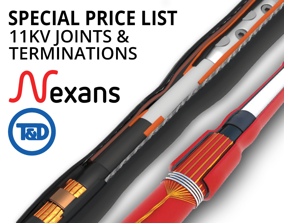
Contact us for Competitive Prices & Fast Delivery from Stocks for Heat Shrink, Cold Shrink & EPDM Rubber Connectors, Joints & Terminations up to 66kV.
Go to our Price List and contact us with your enquiries.
Heat Shrink Cable Accessories for 11kV Triplex Cables
Thorne & Derrick International are specialist distributors of LV, MV & HV Cable Accessories, Jointing, Substation & Electrical Equipment – servicing UK and global businesses involved in cable installations, jointing, substation, overhead line and electrical construction at LV, 11kV, 33kV, 66kV and EHV.
Stocking & Supplying | Duct Seals | Cable Cleats | Cable Glands | Electrical Safety | Arc Flash Protection | Jointing Tools | Cable Pulling Eqpt | Earthing & Lightning Protection | Feeder Pillars | Cable Joints LV | Joints & Terminations MV HV

Euromold MV HV | Cable Terminations, Connectors, Elbows & Joints
Facilitating Sensor Installation In Power Networks By Nexans MV Power Cable Accessories
October 22nd, 2019
The following Press Report has been developed by Nexans, to introduce the new Nexans Euromold Smart Adapter for Sensor Installation
-
Kind Permission: Volker Dobeck -
Marketing Communication Manager at Nexans Power Accessories Germany
Facilitating sensor installation
in power networks
The network distribution system is facing a rapid complexification on the once slow-paced LV grid.
To meet these new requirements, the distribution system operators will need to implement an accurate mesh of measurement of grid parameters as close as possible to the feeding points, enabling a real-time knowledge of network load and status.
Nexans believes, there is a way of meeting the need of enabling sensor installation closest to the feeding while keeping a simple interoperable approach irrelevant of switchgear, spacing and simplifying retrofitting.
As distribution networks move toward smart, the role of MV HV cable accessories suppliers, including separable connectors, becomes more and more crucial in ensuring a convenient/big-scale deployment of the smart grid.
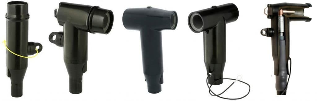
IT’S EASY TO BE SMART WITH AN INTELLIGENT ADAPTER
The network distribution system is facing a rapid complexification pushed by the multiplication of connection of distributed production systems fueled by ever stronger national and international environmental objectives, causing additional and variable load on the once slow-paced LV Grid.
30/08/2019 – Facilitating Sensor Installation In Power Networks
These multiple connection points, be it delocalized generators such as photovoltaic clusters or punctual high-power rating consumers such as EV charging stations, have a local and adverse effect on grid stability, which renders a static load-managed grid design at best very costly, at worst very unreliable. Local authorities are not oblivious to the challenge that this new configuration will mean to the end consumer, as the requirements on quality of service and power feed-in control, as set out in the revised connection code of practice VDE-AR-N 4105. To meet these new requirements, the distribution system operators (DSO) will need to implement an accurate mesh of measurement of grid parameters as close as possible to the feeding points, enabling a real-time knowledge of network load and status.
Thankfully the recent years have seen a steady development of medium voltage low power sensors, which can be easily integrated into the network to supplement the traditional measurement transformers fixed in the substations. But is it really that easy?
A Headache in Perspective
Well, the answer is mitigated and can cause a lot of grey hairs to networks planners.
Indeed, the auxiliary plug-in voltage and current sensors offer a versatile solution to make almost any existing or new network smarter. But on the other hand, the grey areas in normalization have generated a wealth of solutions that are not always interoperable and can be troublesome to select.
Each link of the chain is well defined with regards to its own respective function – passive sensors have to comply to the instrument transformer standards IEC 61869, and power accessories have to comply to the HD 629 standard – but no standardization has been set forth to ensure that sensors and power accessories fit together. And so, planning of installation or retrofitting of equipment is very burdensome as each time every single parameter has to be fully checked in terms of:
- Type of Switchgear:
- AIS and GIS switchgears require different type of accessories, smart connector or termination, and thus different model of sensors
- Sensor Interface:
- Each accessory manufacturer can design its own interface for the piggyback connection, and thus a different model of sensorsSpace requirements:
- Each switchgear has its own design of connecting bay, thus not any type of sensor/connector assembly will fit
- Retrofitability:
- Adding sensors to existing installation will require different installation conditions which have to be verified beforehand
All these pitfalls combined are the sure promise for a lasting headache and “open-heart surgery” on each substation as can be guessed.
A welcome relief for sensor installation
So, is there no other solution than Aspirin?
Nexans believes there is a way of meeting the need of enabling sensor installation closest to the feeding while keeping a simple interoperable approach irrelevant of switchgear, spacing and simplifying retrofitting.
This is achieved by moving the low power transformer measuring point outside of the switchgear and onto the transformer bushing by using a Smart Adapter pre-fitted with the required sensors (fig. 1).

Fig. 1: Smart Adapter KAA4/8 by Nexans EUROMOLD®
In this configuration, most of the complexity is gone (fig. 2).
Fig. 2: Connector arrangement on transformer bushing with cable outlet

- One for all
- On top of the transformer spacing is less of a worry, and the bushing interface is well defined.
- The type of accessory or switchgear is no longer relevant.
- There are no reworks needed for retrofitting, the adapted simple comes plug & play in between the existing accessory and bushing.
- All for one
- Any brand of sensor can be pre-fitted inside the adapter in factory.
- The easy access to the interface allows for easy cabling and flexibility on site during installation.
Future Proof
Who knows what the future holds?
Although today the urgent needs call for network automation and power flow control, having an easy accessible and maintainable sensor array in the grid will enable for the digital revolution of the distribution nodes to come, with big data preventive maintenance applications, intelligent load management and other advanced network healing functions.
About Nexans

Nexans brings energy to life through an extensive range of advanced cabling systems, solutions and innovative services. For over 120 years, Nexans has been providing customers with cutting-edge cabling infrastructure for power and data transmission.
Today, beyond cables, the Group advises customers and designs solutions and services that maximize performance and efficiency of their projects in four main business areas: Building & Territories (including utilities, e-mobility), High Voltage & Projects (covering offshore wind farms, submarine interconnections, land high voltage), Telecom & Data (covering data transmission, telecom networks, hyperscale data centers, LAN) and Industry & Solutions (including renewables, transportation, Oil & Gas, automation and others).
Corporate Social Responsibility is a guiding principle of Nexans’ business activities and internal practices. In 2013 Nexans became the first cable provider to create a Foundation supporting sustainable initiatives bringing access to energy to disadvantaged communities worldwide. The Group’s commitment to developing ethical, sustainable and high-quality cables also drives its active involvement within leading industry associations, including Europacable, the NEMA, ICF or CIGRE to mention a few.
Nexans employs nearly 27,000 people with industrial footprint in 34 countries and commercial activities worldwide. In 2018, the Group generated 6.5 billion euros in sales. Nexans is listed on Euronext Paris, compartment A.
Nexans Power Accessories is the leading European specialised innovator, manufacturer and distributor of low, medium and high voltage accessories as well as connection technology for energy transmission and distribution networks. Longtime know-how and technological advance in cable connection systems was successfully transferred into high voltage applications.
Nexans Power Accessories provide a complete range of slip-on and cold-shrinkable accessories, e.g. premoulded EPDM rubber connectors and silicone terminations, epoxy bushings for transformers and switchgears and joints for power cables up to 170kV. For the international wind industry Nexans also develops and manufactures ready-to-install pre-assembled cable lengths and customized and factory tested cable bridges. An extensive range of additional equipment and a variety of dedicated installation trainings make Nexans a strong partner in the transmission and distribution of wind energy.
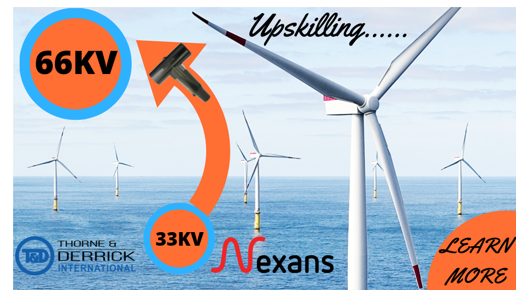
Two Times More Power. Jointers! Empower your CV and skill-set by grasping the 66kV Jointer Training opportunity. Jointers must currently be 33kV Competent and experienced to be ready to undertake the step-up to 66kV from 33kV.
Thorne & Derrick
Nexans Main UK Stockist & Distributor
Contact us for Competitive Prices & Fast Delivery from Stocks for Heat Shrink, Cold Shrink & EPDM Rubber Connectors, Joints & Terminations up to 66kV.
Thorne & Derrick International are specialist distributors of LV, MV & HV Cable Accessories, Jointing, Substation & Electrical Equipment – servicing UK and global businesses involved in cable installations, jointing, substation, overhead line and electrical construction at LV, 11kV, 33kV, 66kV and EHV.
Stocking & Supplying | Duct Seals | Cable Cleats | Cable Glands | Electrical Safety | Arc Flash Protection | Jointing Tools | Cable Pulling Eqpt | Earthing & Lightning Protection | Feeder Pillars | Cable Joints LV | Joints & Terminations MV HV
Euromold MV HV | Cable Terminations, Connectors, Elbows & Joints


