

Blog
BS6387 Fire Performance Cable Joint Kits For Prysmian Max-FOH LV Cables
August 28th, 2018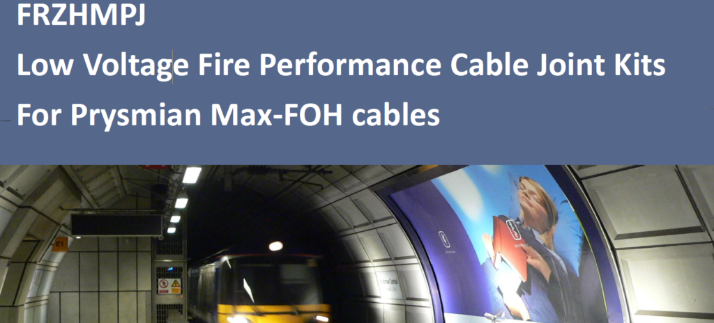
Cable Joints
-
uploaded by Chris Dodds - Thorne & Derrick Sales & Marketing Manager
Cable Joints
BS6387
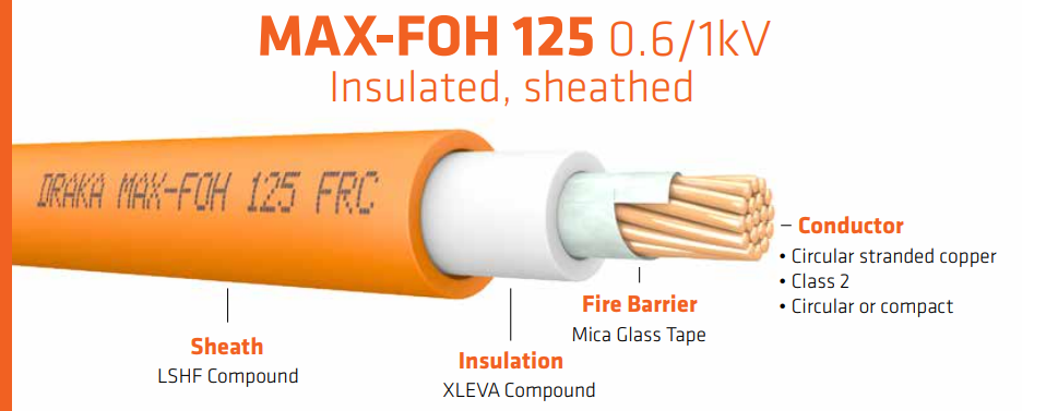
Prysmian FRZHMPJ are Fire Performance & Fire Resistant Cable Joints suitable to install as straight joints for LV Unarmoured and Armoured (SWA AWA) Max-FOH cables with copper conductors up to 1000V:
- Single Core 1.5sqmm-1000sqmm
- Multi Core 1.5sqmm-400sqmm
See the following download for the full and complete technical specification for Prysmian FRZHMPJ cable joints.
Cable Joint Kit Standards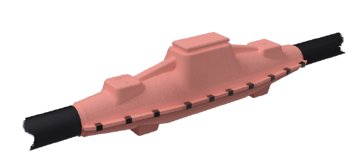
The cable joint kits and shells include rigid glass reinforced phenolic joint shells which are fire retardant and LSOH (Low Smoke Zero Halogen) – the following fire tests have been conducted on the cable joints:
- BS EN 50393:2015 – Test methods and requirements for accessories for use on distribution cables of rated voltage 0.6/1 (1.2)kV.
- BS6387:2013 – Test method for resistance to fire of cables required to maintain circuit integrity under fire categories (Categories C, W & Z).
- IEC 61034-2:2005+A1:2013 – Measurement of smoke density of cables burning under defined conditions
♦ BS6387 – Test method for resistance to fire of cables required to maintain circuit integrity under fire conditions.
Thorne & Derrick are distributors for the complete range of Prysmian Cable Joints for the reliable and safe jointing of industrial, hazardous area and fire resistant power cables to BS6387 standard.
View our complete range of LV Cable Joints.

Triplex Terminations 11kV – NPG Northern Powergrid
August 28th, 2018
-
uploaded by Chris Dodds - Thorne & Derrick Sales & Marketing Manager
Cable Terminations
The following information is uploaded to assist in the selection and specification of the correct Triplex terminations to suit 11kV XLPE insulated cables with copper wire screen typically in accordance with BS7870 – the cable terminations manufactured by 3M Electrical are Cold Shrink type from the QTIII range of indoor cable termination kits.
These MV HV Cable Terminations are approved for use by Northern Powergrid (NPG) jointers and their framework contractors for the termination of 11kV Triplex cables – a complete range of Cold Shrink Terminations are available for 11kV, 33kV and 66kV single and 3-core cables with XLPE or EPR type insulation.
| Cold Shrink Termination | 92-EP621-1-NY43 | 92-EP631-1-NY44 | 92-EP641-1-NY45 | 92-EP641-1-NY52 |
| NPG Catalogue Number | 163660 | 163661 | 163662 | 163663 |
| Cable Termination (CSA) | 95sqmm | 185-300sqmm | 400sqmm | 630sqmm |
| Suits XLPE Insulation Diameter | 16.3-27.4mm | 21.1-38.9mm | 26.7-45.7mm | 26.7-45.7mm |
For Example:
Northern Powergrid NPG – Bill Of Materials For 11kV Triplex Termination Kit NPG163662
Cable Termination Kit List – Triplex Terminations
- SED T110-T 3M Cold Shrink Cable Termination Body x 3
- NEDL80 Sicame ML4/14/12 Earth Lug (Copper Wire Screens Pictured)
- NEDL19 Sicame HVTM1/3-12B Brass Cable Lug (Stranded & Solid Core Conductors)
- Jointing Instruction 2919-0
Earthing & Terminating
11kV Triplex Copper Wire Screens
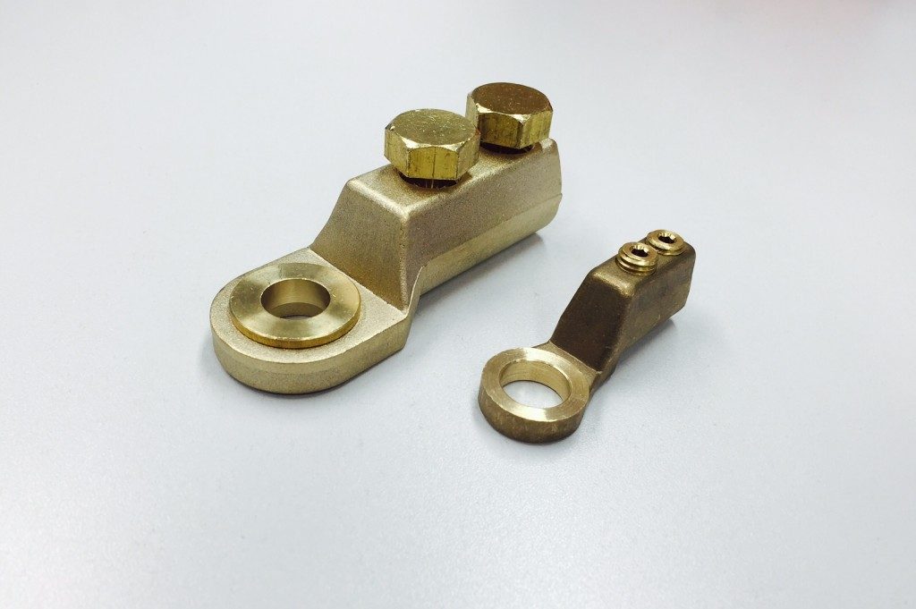
Sicame ML4 range of mechanical cable lugs are designed for the termination of stranded/solid/circular conductor cores – also used for the termination of earth screen wires of MV-HV polymeric cables as a component of Triplex terminations kits.
The mechanical lugs are manufactured in copper alloy and suitable for jointing either copper or aluminium cored conductor – see complete range of Sicame cable lugs.
NOTE: Triplex cable terminations are supplied as sets of 3 – to terminate 11kV cables onto private networks using heat shrink cable terminations please go to Triplex terminations.

THORNE & DERRICK SPECIALIST ELECTRICAL DISTRIBUTOR
LV ♦ MV ♦ HV
T&D distribute the most extensive range of LV, MV & HV Cable Jointing, Terminating, Cable Pulling & Installation Equipment – we service UK and international clients working on underground cables, overhead lines, substations and electrical construction at LV, 11kV, 33kV and EHV transmission and distribution voltages.
- Key Products: MV-HV Cable Joints & Terminations, Cable Cleats, Duct Seals, Cable Transits, Underground Cable Protection, Cable Jointing Tools, Feeder Pillars, Cable Ducting, Earthing & Lightning Protection, Electrical Safety, Cable Glands, Arc Flash Clothing & Fusegear.
- Distributors for: 3M, ABB, Alroc, Band-It, Catu, Cembre, Centriforce, CMP, Elastimold, Ellis Patents, Emtelle, Furse, Lucy Zodion, Nexans Euromold, Pfisterer, Polypipe, Prysmian, Roxtec.

LV – Low Voltage Cable Joints, Glands, Cleats, Lugs & Accessories (1000 Volts)

MV HV – Medium & High Voltage Cable Joints, Terminations & Connectors (11kV 33kV EHV)

Cable Laying – Underground Cable Covers, Ducting, Seals & Cable Pulling Equipment
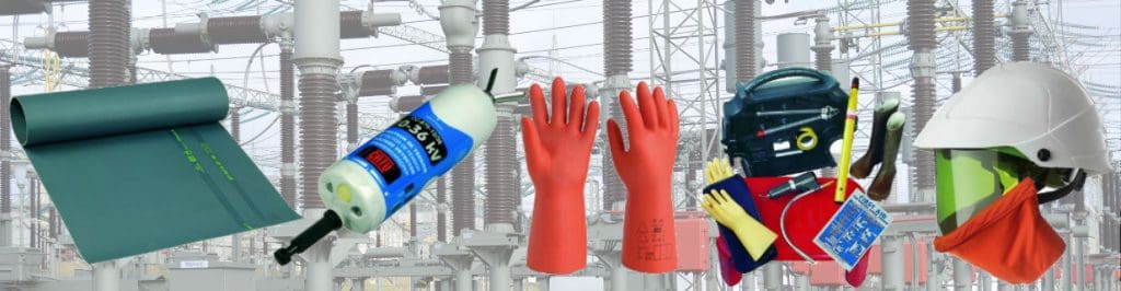
T&D, CATU Electrical Safety & Arc Flash Protection Specialists for SAP’s, Linesmen, Jointers & Electrical Engineers – Largest UK Stockist
Landlords Feeder Pillars – An Example Specification
August 28th, 2018
Feeder Pillars
-
uploaded by Chris Dodds - Thorne & Derrick Sales & Marketing Manager
Thorne & Derrick are the leading designer, distributor and supplier in the UK of feeder pillars manufactured by Lucy Zodion – a complete range of standard, customised and pre-wired types from the Lucy Fortress range of feeder pillars are available to suit all LV Electrical Power Distribution requirements.
This includes power distribution pillars to provide LV electricity supply to new housing developments, multi-occupancy buildings and permanent supply kiosks for properties.
Here follows an example of a Landlords Feeder Pillar specification highlighting the flexibility and capability of Thorne & Derrick to liase with consultant engineers and specifiers to meet the needs and electrical power requirements of the residential, housing and accommodation market sectors.
FEEDER PILLARs
21.1 A new landlords service is to be provided as indicated on the drawing. This will consist of a weatherproof secure enclosure housing a distribution board, commonly referred to as a feeder pillar.
21.2 Provide a Thorne & Derrick International landlords feeder pillar. Type Fortress size 16 hot dipped galvanised feeder pillar finished in RAL 6026 complete with Yale lock and door activated internal lighting kit options.
21.3 Provide a concrete base for the feeder pillar in accordance with the manufacturers specifications.
21.4 Provide a MEM Memshield 3 125A 8 way TPN distribution unit to the landlords feeder pillar.
21.5 Provide attendance for electricity meter installation.
21.6 Provide 16sqmm 6491X single core PVC cable tails for DNO ISU in 100mm galvanised trunking.
21.7 Provide local isolator to DNO ISU electrical intake.
21.8 Cable from isolator to DB in 16sqmm 6944X (4 core cable) + 10sqmm CPC 6419X.
21.9 Refer to feeder pillar distribution board schedule for further details.
21.10 Provide 4 number 90mm twinwall cable ducts through concrete base for buried electrical service connections.
22 LANDLORDS SERVICES TO CANOPIES
22.1 The front canopies are to be to be partially stripped and altered.
22.2 Refer to the removal of services section for necessary removals and adaptations necessary to effect the works.
22.3 New ambient down lighting shall be provided to the canopies as detailed on the drawing. Provide new luminaires as detailed on drawing. The existing electrical and lighting circuits have been identified on the as installed information (provided for reference) and utilised for the new lighting. Each unit has an independent circuit. Identify existing feed and extend the circuit to the new luminaires. New cabling to be 1.5sqmm 3182B flexible Low Smoke Zero Halogen (LSZH) cable.
22.4 Provide connections to proposed canopy bus stop signs as detailed on the drawing. These signs shall be wired off the existing canopy lighting circuits. New cabling to be 1.5sqmmmm 3182B.
22.5 Dependant on phasing, alterations to the canopy will expose circuits running through one canopy onto the next. Allow to dress and protect these electrical circuits during the course of the works.
A downloadable specification form is available to initiate the electrical engineering design of all Lucy Zodion type feeder pillars.
Custom Feeder Pillars are readily available in a range of special and format feeder pillars to meet specific applications; they can be made from galvanised steel , or stainless steel and can be painted to suit the customers individual needs.
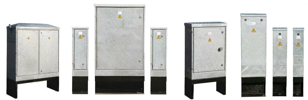
Galvanised & Stainless Steel | Cast Iron | GRP | Pre-Wired | Electrical Power LV

Largest UK Feeder Pillar Stocks – fast delivery from stock or on short lead-times

➡ Further Reading
THORNE & DERRICK SPECIALIST ELECTRICAL DISTRIBUTOR
LV ♦ MV ♦ HV
T&D distribute the most extensive range of LV, MV & HV Cable Jointing, Terminating, Pulling & Installation Equipment – we service UK and international clients working on underground cables, overhead lines, substations and electrical construction at LV, 11kV, 33kV and EHV transmission and distribution voltages.
- Key Products: MV-HV Cable Joints & Terminations, Cable Cleats, Duct Seals, Cable Transits, Underground Cable Protection, Cable Jointing Tools, Feeder Pillars, Cable Ducting, Earthing & Lightning Protection, Electrical Safety, Cable Glands, Arc Flash Clothing & Fusegear.
- Distributors for: 3M, ABB, Alroc, Band-It, Catu, Cembre, Centriforce, CMP, Elastimold, Ellis Patents, Emtelle, Furse, Lucy Zodion, Nexans Euromold, Pfisterer, Polypipe, Prysmian, Roxtec.
LV – Low Voltage Cable Joints, Glands, Cleats, Lugs & Accessories (1000 Volts)
MV HV – Medium & High Voltage Cable Joints, Terminations & Connectors (11kV 33kV EHV)
Cable Laying – Underground Cable Covers, Ducting, Seals & Cable Pulling Equipment
T&D, CATU Electrical Safety & Arc Flash Protection Specialists for SAP’s, Linesmen, Jointers & Electrical Engineers – Largest UK Stockist
Fire Stopping Cable Ducts
August 28th, 2018
A Guest Article by Carl Pike – Director Filoform UK
The following contributed post provides an overview of the dangers of inadequately protected building penetrations and the need for duct sealing solutions with independently tested fire-proofing specification to protect people and property against the devastating effects of fire.
What is Fire Stopping?
Fire stopping has been brought more to the fore over the last few years than ever before.
The best way to explain the need of a fire-stop is to treat a multi-room dwelling or factory or any structure as a series of boxes or compartments. These boxes need to join physically by their walls or floors, even doors or windows. All these items are regulated and proven fire withstand products and procedures are in place to ensure any building is built or modified in accordance with the underlying need to stop fire spreading.
The fire tightness of one of these boxes is only as strong as the weakest entry point.

Did you know, fire can double in volume per minute it is lit. It doesn’t take long at this alarming rate to fill a room with fire. Fire does not respect any boundaries put in its place, but a certified system like ‘FiloSeal+HD FIRE‘ installed in the correct manner will stop or prevent the premature spread of fire to the next compartment through cable ducts, entries or penetrations.
Fire stopping got its foothold first in the marine industry. Probably because a loss of integrity of one compartment will mean a total loss of the vessel. It was in fact a development from the second World War German super sub captured by the Swedish that led to fire stopping products of a modular nature being developed by a company still going today. In the super sub, the system was used to prevent the rattle of pipes and wires within the sub, hence improving the sound signature of a hidden submarine.
Research we have done leads us to the improving of fire stopping on land as a direct result of several disasters in the USA starting with the 1906 San Francisco earthquake. This was followed by the New York garment district factory fire of 1911 and perhaps most scarily by the Browns Ferry Nuclear plant fire of 1975. This last event was caused by an open candle flame being used to detect air path leaks in foam based cable and pipe transit areas!
Not surprisingly, the nuclear industry was the first on land industry to take fire stopping seriously.
The use of the correct fire stopping product in the correct way and in the correct place ensures fire tightness of a compartment or room. There are plenty of products which work on floor/wall or ceiling wall interfaces. Many of these are flexible to allow for building expansion and contraction. Some other ways of sealing do not allow for this expansion; cements and mortars for instance. These materials do have their place but not always.
The last area we have not yet mentioned is the service penetrations into a room or compartment. These are the necessary services such as water, electricity and data cables which without them a room is almost useless.
Penetrations may come in via a wall, floor or ceiling. All must be adequately and correctly fire stopped. These services will need a flexible and re-enterable method of being sealed. The flexibility due to temperature expansion of both cables and pipes; the re-enterability due to the almost constant development of a buildings use and services.
Rockwool and insulation’s of the type are fire-retardant but are not in themselves a fire stopping method. They are perfectly suited to holding a system in place during installation but should never be relied upon to be the actual stop itself.
Fire stopping expanding foams
Please don’t get us started with this.
The use of so-called ‘fire rated’ foams for fire stopping of service penetrations or control joints is sadly becoming more prevalent everywhere. This trend could lead to serious consequences if a fire happens in a building where they’re used,
What do we mean by ‘fire rated foams’?

The fire rated foams we’re talking about are those that are delivered by way of an aerosol can or canister, which foam up when they’re dispensed – much like canned shaving foam.
They’re typically polyurethane based, and our understanding is they might all be coming from the same factory overseas, imported under many different product brands. To add to the problem, many are now dyed red or pink like above to signify their suitability for fire stopping applications. DON’T USE THEM!
Modular sealing systems work admirably out at sea where rigorous compliance is ensured on a day to day basis. On land, a more flexible system would work better; one where less is known up front about the exact cables or pipes to be found in any service penetration. One that can cope with irregular sized holes and mis-shaped ducts.
The correct system to use in service penetrations ON LAND
Their are many fire rated sealing systems available that claim their product is suitable for penetrations with cables present but you must really be careful and select the correct product for the situation you are sealing. Important note; a fire rating applies to an ‘as fire tested’ system, or an otherwise approved configuration. Only when a particular (and I must add proprietary) brand of product is installed in an identical way to the approved configuration does the entire system or configuration achieve the fire rating as described.
Filoform has heavily invested time and money into developing a fire rated duct sealing solution that offers the user and and end customer the following;

Flexible & Simple – a one box solution that has everything is one kit to seal a cable duct regardless of the size or number of cables running through the duct – we’ve kept selecting and installing our product ‘simple’ little upfront planning needed.
NON Hazardous – FiloSeal+HD FIRE contains no hazardous chemicals which makes COSHH and getting our product approved with any Health & Safety departments an easier process.
Many Resistances – Not only is our product fire resistant, tested to BS EN1366-3:2009, it also offers, 2 bar pressure resistance against water and gas / rat, rodent and termite protection (Mastotermes Darwiniensis) Northern Australian termites) and resists many harsh chemicals and gases, for example, Hydrogen Sulfide, Methane, Chlorine, Hydrocarbons and many more.
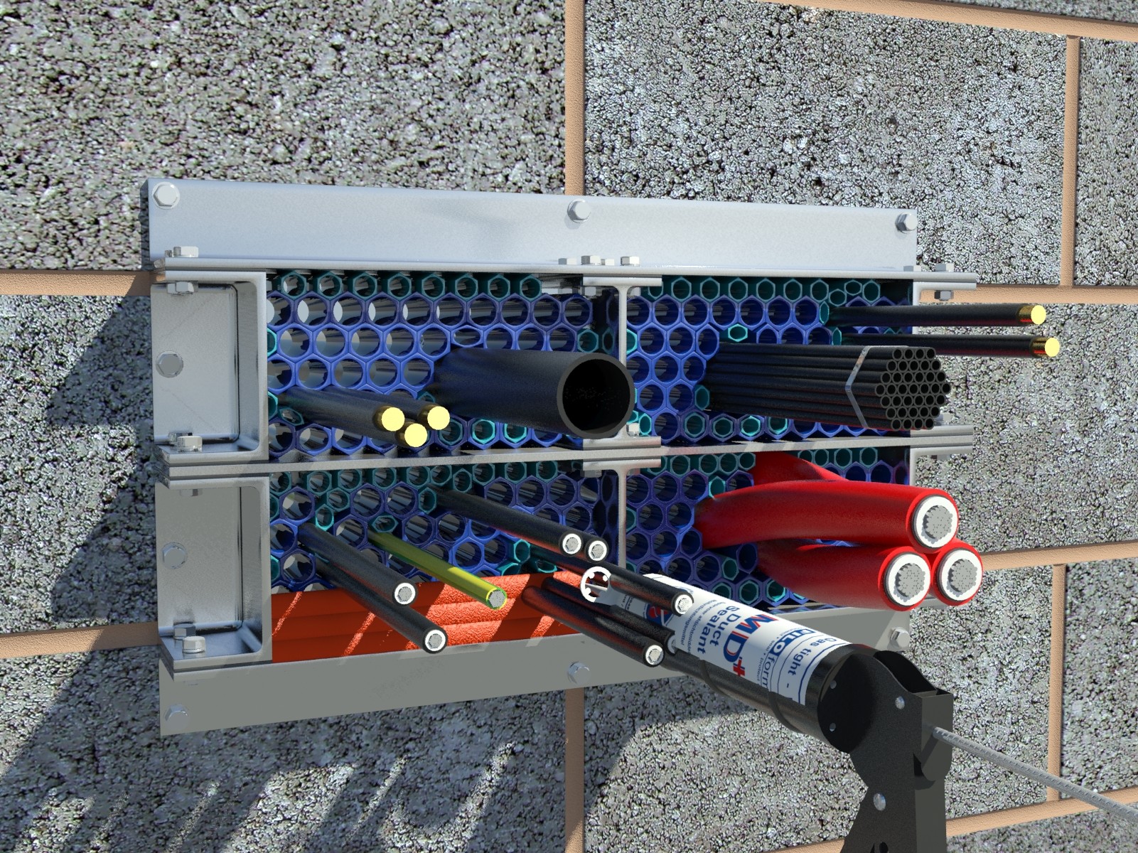
Expandable – We’ve developed FiloSeal+HD FIRE to easily be installed in circular ducts and also irregular shaped penetrations. FiloSeal+HD FIRE can be supplied with a retrofittable cable transit frame which is used if a structure or space will not allow fitting of a seal into the structure itself.
Affordable – Even with the heavy investment and time we spent designing and developing FiloSeal+HD FIRE, we’ve made this cable duct seal affordable but still offering extremely high quality components with proven test reports and a solid history of sealing solutions.
FiloSeal+HD FIRE provides a strong support system using the fire resistant hexagonal blocks made of our specially formulated material called ‘Formite’ which builds up like a honeycomb structure.
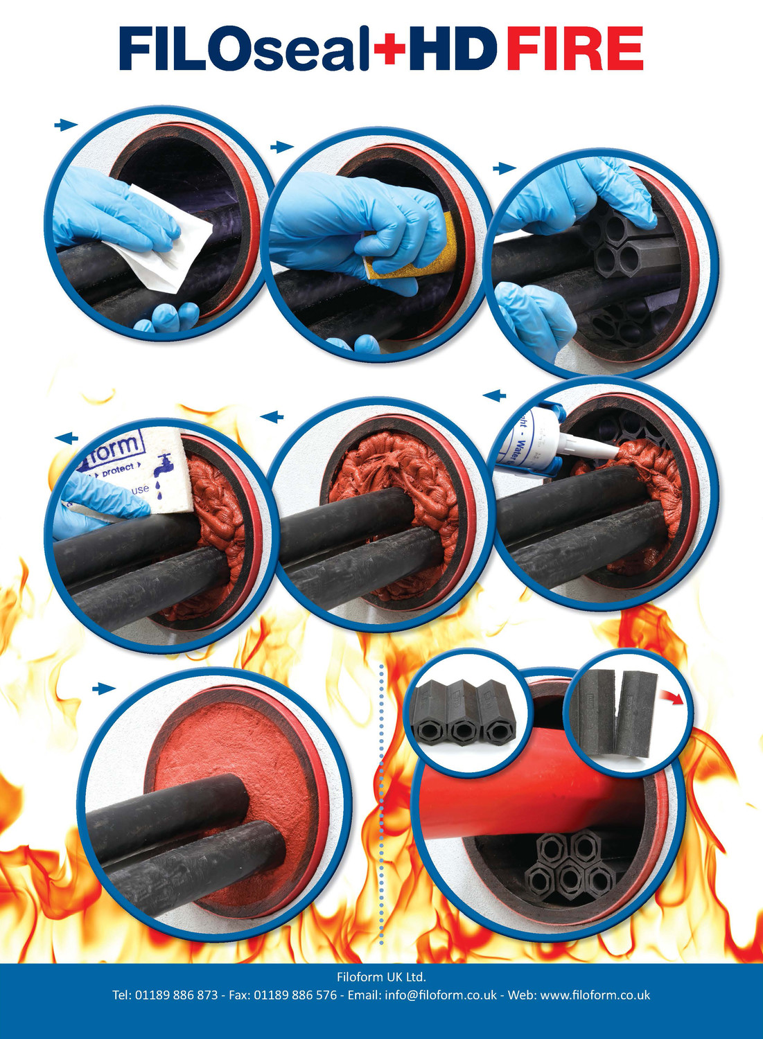
FiloSeal+HD FIRE is suitable for sealing empty or any cable configuration or pipes contained in one duct and also allows easy re-entry of the seal to add or remove cables or pipes as required.
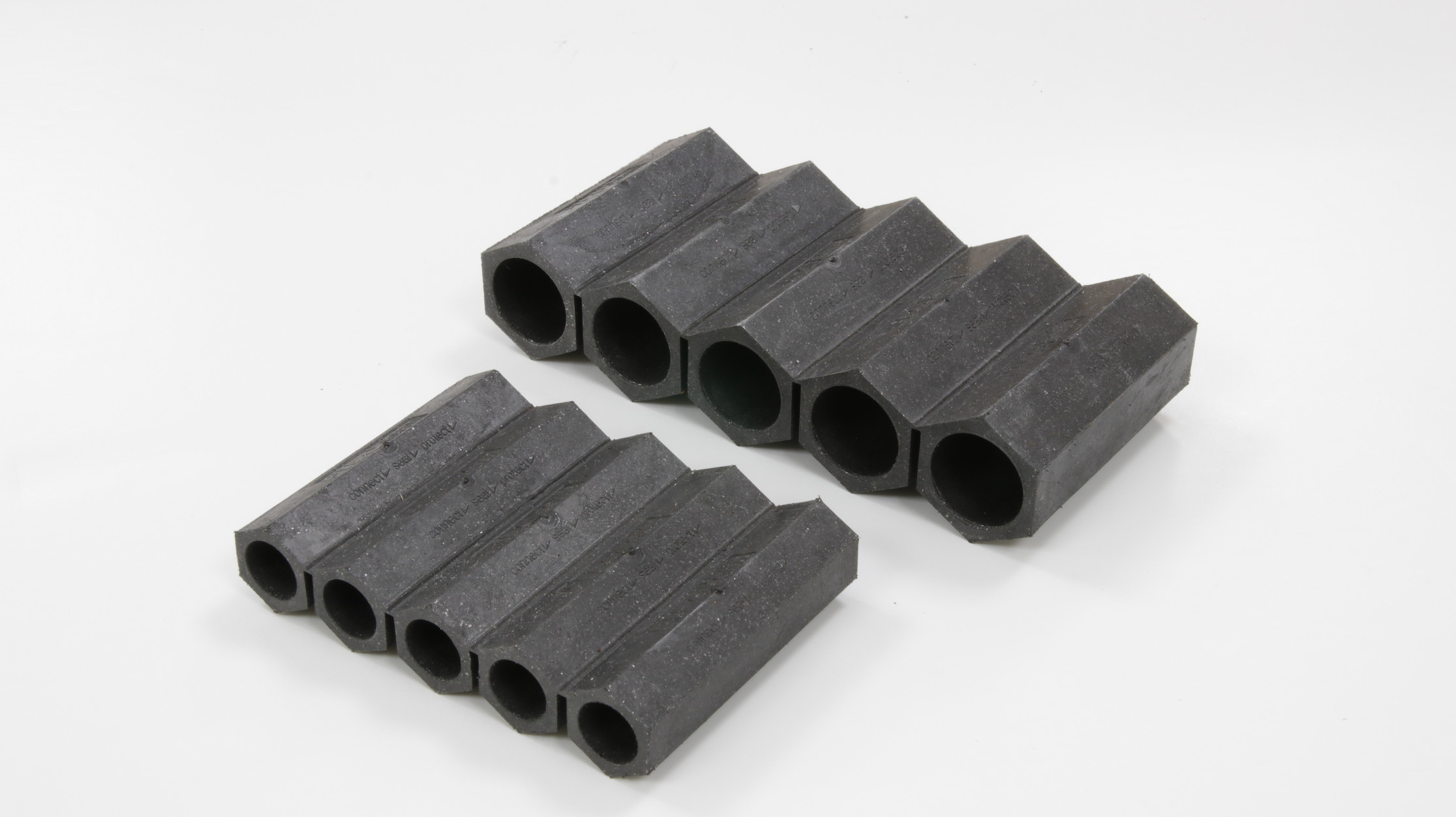
Filoform FiloSeal+HD FIRE
FiloSeal+HD FIRE is very easy to apply regardless of the type of cable scenario in the cable ducts as it uses strong, but flexible hexagonal blocks to support the cable and provide a strong backing for the seal.
The unique design of the hexagonal blocks makes positioning and separation of the cables very simple while also providing a strong backing for the MD+ to be applied on.
- Up to 4 hours fire resistance in transit frames (single side)
- Up to 4 hours fire resistance in ducts
- Tested to BS EN1366-3 2009
- Up to 2 bar Pressure Resistance
- 100Kg pulling Force on the cables when sealed
- 10xd at 45º, with 1 bar pressure bending test
THORNE & DERRICK SPECIALIST ELECTRICAL DISTRIBUTOR
LV ♦ MV ♦ HV
T&D distribute the most extensive range of LV, MV & HV Cable Jointing, Terminating, Pulling & Installation Equipment – we service UK and international clients working on underground cables, overhead lines, substations and electrical construction at LV, 11kV, 33kV and EHV transmission and distribution voltages.
- Key Products: MV-HV Cable Joints & Terminations, Cable Cleats, Duct Seals, Cable Transits, Underground Cable Protection, Cable Jointing Tools, Feeder Pillars, Cable Ducting, Earthing & Lightning Protection, Electrical Safety, Cable Glands, Arc Flash Clothing & Fusegear.
- Distributors for: 3M, ABB, Alroc, Band-It, Catu, Cembre, Centriforce, CMP, Elastimold, Ellis Patents, Emtelle, Furse, Lucy Zodion, Nexans Euromold, Pfisterer, Polypipe, Prysmian, Roxtec.
LV – Low Voltage Cable Joints, Glands, Cleats, Lugs & Accessories (1000 Volts)
MV HV – Medium & High Voltage Cable Joints, Terminations & Connectors (11kV 33kV EHV)
Cable Laying – Underground Cable Covers, Ducting, Seals & Cable Pulling Equipment
T&D, CATU Electrical Safety & Arc Flash Protection Specialists for SAP’s, Linesmen, Jointers & Electrical Engineers – Largest UK Stockist
An Installation Guide For Feeder Pillars
August 22nd, 2018Installation Of Retractable Type Feeder Pillars Manufactured by Lucy Zodion
-
uploaded by Chris Dodds - Thorne & Derrick Sales & Marketing Manager
Feeder Pillars
INTRODUCTION
This article covers the installation and maintenance of Pre-wired Feeder Pillars & Retractable Power Pillars as distributed by Thorne & Derrick and manufactured by Lucy Zodion.
This article is to provide assistance to the end user in the installation, maintenance and operation of their feeder pillars – it is not exhaustive and a suitably qualified person should be consulted if in any doubt. It is important to note that any modifications made to the pillars without authorisation by Lucy Zodion are outside the scope of this article.
Retractable Type Feeder Pillars
Lucy Zodion supply two types of retractable power supply feeder pillars namely ‘Castle’ and ‘Westminster’ types – these feeder pillars are part of the Lucy Fortress range of Low Voltage Electrical Distribution Equipment.
These feeder pillars mount flush to the top paving surface when not in use and are pulled up for use when LV power supply is required. Feeder pillars typically supply low voltage power sockets for supplying temporary power to events such as markets, outdoor events and broadcasting. Pillars are available in a variety of specifications, including single and three phase electrical connections and data sockets, as specified by the end user.
A downloadable specification form is available to initiate the electrical engineering design of all Lucy Zodion type feeder pillars.
♦ Electrical Regulations
This Blog written with the support of Lucy Zodion should be read in conjunction with BS 6423:2014 (this replaced BS 6423:1983), the Code of Practice for maintenance of LV electrical switchgear and control gear for electricity voltages up to and including 1000V/1kV.
All electrical work should be conducted in accordance with the Electricity at Work Regulations 1989.
All feeder pillar installations should be designed, tested and installed in accordance with the IET Wiring Regulations BS7671 Requirements for Electrical Installations – any other local regulations in force at the time should be observed.
Installing Feeder Pillars
Pre-wired Electrical Distribution Feeder Pillars
Prewired pillars can be mounted either on the supplied metal root, which is buried in the ground see Figure 1 below, or bolted directly to a concrete base.
Lucy Zodion do not specify the exact nature of installation as it is the customer’s duty to consult a suitably qualified civil engineer for feeder pillar installation.
The following procedure is for guidance only:
- Excavate a trench to the depth of the root section plus the depth of the solid base the unit will mount on, and approximately 30 cm greater than the width and depth of the feeder pillar
- Lay a solid base to the trench, for example paving slabs
- Place feeder pillar on to base and draw cabling into pillar
- Backfill trench with suitable gravel
- We advise capping of the gravel with concrete in the base of the feeder pillar and make good the surrounds with suitable material
➡ It is the customer responsibility to ensure the suitability of the site for the feeder pillar unit specified.

Figure 1 Pre-wired Feeder Pillars – Method of Installation
Retractable power pillars are mounted flush with the existing road/paving surface, and have recesses manufactured at a suitable depth to continue the existing surface material onto the folding
doors of the feeder pillar to leave a safe installation with low visual impact.
Figure 2 below is supplied for guidance only and a suitably qualified civil engineer should always be consulted to determine the exact method of installation.
It is crucial that the unit is equipped with suitable drainage. Lucy Zodion recommend using a 100mm drain pipe with positive drainage to the main sewer. While the low voltage installation is IP67 rated, incorrectly replaced caps and covers allow opportunity for ingress of water and long term exposure can permanently damage to internal components of the feeder pillar.

Figure 2 Westminster Retractable Feeder Pillar – Method of Installation
Westminster Retractable feeder pillars are supplied with recess pockets of a suitable depth for the proposed infill material. This depth is specified at order. Infill material must be installed flush with the surface and around the lock cover and hinges. Some means is necessary to hold the material in place when the feeder pillar is in the vertical, raised position, e.g. solvented grab adhesive.

Figure 3 – Top Cover Of Westminster Retractable Feeder Pillar
Electrical Requirements
Pre-wired feeder pillars and retractable power pillars are supplied pre-wired and tested at Lucy Zodion’s factory. A copy of the test documentation, along with a schematic drawing of the Lucy Zodion supplied equipment, is supplied with the pillar. It is assumed that electrical installation is conducted by a suitably qualified and skilled person and the following information is for general guidance only.
➡ A full test in accordance with BS7671 must be carried out, and a certificate issued, by the installing party after installation on site.
Electrical Connection Of The Feeder Pillar
Feeder pillars are typically supplied with a single phase 230V or 3 phase 415V electrical power supply feed from either a DNO/REC or private supply. Suitable space has been left for installation of DNO/REC cut-out if specified; this can be verified with reference to the drawings supplied with the pillar.
DNO/REC power supplies are connected to the pre-installed equipment using the pre-wired double insulated tails from the main switch disconnect.
Private supply feeder pillars are wired into the equipment using the customer’s cable.
The cable may be wired and connected directly into the main switch disconnect, wired through a cable spreader chamber or wired into a terminal enclosure depending on the size of the incoming cable.
The provision for terminating incoming cable can be determined from the drawings that accompany the feeder pillar or identification of the parts on the pillar.
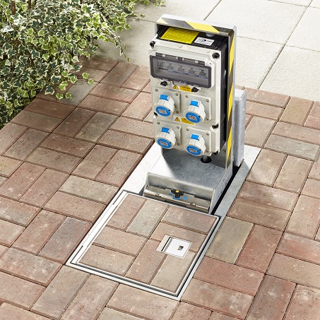
Lucy Zodion Westminster Feeder Pillars – In Ground Power Distribution Pillars | LV Power Distribution
Lucy Westminster Feeder Pillar Features
- Modified lift assist at first lid to improve longevity and operation ease
- Lift assist added to tower for smoother and safer set-up
- Improved locking system for vibration resistance
- Enhanced Tower latching with slam lock means quick and easy access

Lucy Westminster – Versatile, Discreet , Robust & Safe Power Pillars
Cable Terminations
As feeder pillars are often located remotely from the electrical equipment they supply the outgoing cable sizes often have a large cross-sectional-area for the current rating and cannot be terminated directly into the pillar equipment.
For large outgoing CSA cable sizes suitable cable termination equipment, terminal studs or blocks, are supplied pre-wired into a terminal box.
Incoming and outgoing cables should be wired into these terminals, if supplied, to avoid overcrowding on the main distribution board or where equipment is unable to accept cables of the size specified.
Smaller cable sizes can be wired directly onto the equipment as appropriate.
Suitable space has been left for the cable glanding of outgoing unarmoured or armoured cables, in the form of cable gland plates on the distribution or terminal enclosure, a cable spreader chamber or a horizontal length of galvanised trunking.
Earthing
A dedicated ten way, brass earth block with an adjacent label reading ‘SAFETY ELECTRICAL CONNECTION, DO NOT REMOVE’, is supplied in a prominent and easily assessable location on the feeder pillar backboard. The pillar and all accessible metal parts within the pillar and all CPC earth in pre-wired equipment are equipotentially bonded to the earth block.
It is essential that pillars are connected to a suitable earth upon installation.
Electrical Connection Of The Feeder Pillars
Retractable feeder pillars are supplied with a terminal enclosure mounted in the fixed base of the unit and attached to the outgoing circuits via a pre-installed flexible cable. Once cable terminals have been connected and appropriate tests conducted the supplied Magic Gel should be used.
Magic Gel Instructions:
- Empty both sachets into a suitable mixing container
- Mix thoroughly; pour into the terminal box to above the height of the terminals
- The Magic gel starts to cure in about 4 minutes and will fully cross-link in about 10 minutes depending on temperature
- The Magic gel can be broken up and removed should the installation require alteration
In all cases the installation must be connected to a suitable earth supply. The installer should check the earth loop impedance of the installation as this cannot be verified at the factory. Unsupported lengths of cable should be kept to a minimum.
Where there is more than one cable they shall be connected along their length at not more than 1 metre intervals.
Operation : Pre-wired Pillars
This section covers standard equipment often supplied pre-wired into Lucy Zodion pillars.
For special equipment not covered in this manual please contact Thorne & Derrick.
All pre-wired pillars are supplied with isolation devices which can be locked off.
It is essential that the supply is isolated before any covers are removed from enclosures. For work to be carried out on the incoming terminal board or switch disconnect it is necessary to isolate the supply coming into the feeder pillar.

Figure 4 Common Components of Pre-Wired Pillar
Switch Disconnect
Switch disconnect isolates the main incoming supply from the rest of the equipment in the feeder pillar.
Switch disconnects may be SP & N, TP & N, SP&SN or TP &S N as required by the customer.
In cases where a switched neutral is installed the live phases always cut out first when the switch is disconnected. All main isolators are capable of being locked off to allow safe working on the equipment.
It is essential to lock-off the device when working remotely from the pillar, for example double sided or double length feeder pillars, or equipment being supplied from the pillar.
Switch disconnects may be Fuse Combination Units which are suitable for making, breaking and isolation. The correct fuse for the device is installed prior to the unit leaving the Lucy Zodion factory.
Should the fuse require replacement it is essential that the correct rating of BS88 HRC fuse is fitted. The switch fuse can be locked-off to isolate the rest of the system from the incoming electrical power supply.
24 Hour Board
24 Hour Board provides a continuous, overload protected supply to electrical equipment within installation.
Usually this supply is the main panel board or fuse board of the installation.
In cases where the main board is group switched an auxiliary board will be supplied to supply 24 hour power the pillar equipment (e.g. light, heater and socket) and the group switch control equipment.
Socket outlets
Socket outlets for use by normal persons are supplied as standard via an overload protected, residual current device, e.g. RCBO, RCCD on the 24 Hour board. Periodic testing of this device is required via the test button on the unit.
Group Switch
Group switch controls a group of equipment, typically street lighting installations, via a control system, such as a photocell or timer. Be sure to isolate a group switch from the incomer on the 24 Hour board, as group switches are remotely controlled they can go live at any time.
Group switch control – the group switch can be controlled by a timer, photocell or an override. A typical installation with a group switch would control street lighting.
- Solar Time Clock – is pre-set in the factory for the final geographical location of the pillar. To override the time switch press and hold the two central buttons on the controller until the output condition of the unit changes in the display.
- Photocell – either one or two part, switches the group switch contactors when ambient light levels fall below pre-determined level. One part photocells have the sensor mounted on the side of the pillar as standard. Two part photocells allow the installer to install the sensor head remotely from the pillar, the terminal from the photocell are wired into the unit in the pre-mounted 125x125mm enclosure within the pillar.
- Override Switch – switches the contactors on for testing of outgoing circuits, or for functional switching of the load. The use of a timer in conjunction with a photocell allows the lighting to be illuminated when either light levels or time dictates
Residual Current Devices
Residual current devices all socket outlets are protected by a residual current device as well as suitable overload protection. It is the end users’ responsibility to ensure that all equipment connected to sockets within the feeder pillar is within the specified load and connected by a suitable cable as required by BS7671. All residual current devices should be tested periodically and at least every six months.
Surge Protection
Surge protection devices are installed, if specified, to suit the earth system indicated by the customer e.g. TT or TNS. Should the earth system change from the original specification it will be necessary to change the surge protection device. The surge protection device has an end of life indicator based on the amount of KVA diverted to earth. This requires periodic inspection. Should the device indicate an end of life condition the unit will need to be replaced by a competent person.
Operation Instructions
Raising and lowering: – the unit is unlocked using the supplied T key. The key is inserted and twisted through 90 degrees. The key is held in the lock and is used as a handle to pull the top cover open. The socket unit is raised using the handle on the top and locked into position using the two retractable lugs. The cover is subsequently lowered back into position.
The socket box is fitted with a tilt switch which switches on the supply to the unit as it is raised. The LED on the top of the box indicates that the power is connected. Plugs are connected into the sockets by rotating the cover anti-clockwise until it is released and able to swing up. The sockets are functionally switched using the toggle switch on the RCD.
➡ To maintain the IP rating of the unit all caps must be properly replaced on the sockets and the RCD cover fully tightened before the unit is lowered after use. Lowering is the reversal of opening.
Electrical Supply
Functional switching for sockets is provided by the isolation switch on the RCD. The transparent plastic cover provides ingress protection to the residual current devices. To access the switches rotate the knurled thumbwheels anti-clockwise until the bolt exit the hole and pull down the flap. Sockets are activated by pushing the switch into the up position.
Test the functioning of the residual current device at the time of switching. This is achieved by pressing the test button, upon which the power should instantly be cut and switch revert to the down position. It is essential that the transparent cover is closed while the pillar is in use in order to avoid possible contact between water and electrical parts.
Retractable power pillars are fitted with cenorm style outdoor sockets with a minimum ingress protection of IP67.
Generally sockets will be 16A or 32A Single phase or 3 Phase. Single phase sockets are identified by a blue body and three phase by a red body, current ratings are printed on
the labels on the socket cover. Sockets and plugs of different types are not interconnectable and only plugs that match the current and phase rating of the socket should be plugged into it.
To open socket covers, rotate the grey outer wheel quarter turn and hinge the cover upwards. Holding the cover up, plug the plug into the socket, with the tang pointing downwards. The cover should locate with the raised lug on the socket to ensure security of installation. Removing the plug is a reverse of the process and it is essential to ensure all covers are properly replaced before lowering the power pillar.

Figure 5 Westminster Socket Box
Inspection & maintenance
➡ Warning: Feeder pillars may contain accessible live parts even when the unit has been isolated. Equipment covers should only be removed by skilled and authorised personnel.
The following recommendations are for guidance only as the nature of the environment and the conditions of operation will have a significant influence on the maintenance schedule required.
General Maintenance Policy
This document describes the routine maintenance requirements of Lucy Zodion Pre-wired pillars and retractable power pillars. It is assumed throughout that necessary precautions to render the apparatus safe to work on have been undertaken by suitably qualified personnel.
Conditions of use will have a significant impact on the service intervals of the equipment and it is advised that when units are installed in adverse conditions such as coastal areas, areas of high pollution, very frequent switching of loads or areas accessible to the public, that the maintenance interval is reduced to ensure reliable and safe operation of the equipment.
Under normal conditions of service, Lucy Zodion Prewired Pillars and Retractable Power Pillars are intended to give years of trouble free service. The best way to ensure trouble free service of your product is to conduct regular visual inspections and report any defects to a suitably qualified person for maintenance. As the retractable pillar is located below ground level, it is recommended that the adjacent area is kept clean around the lock mechanism.
Safety Precautions
Only skilled and instructed persons may remove covers from enclosures within the pillars. In order to avoid live working, installations should be isolated from the supply prior to maintenance within enclosures. General good housekeeping techniques, including the regular removal of any foreign bodies that have fallen into the tub are recommended as part of the maintenance programme.
* Incorrect alignment with a suitable drainage point, or blockage to existing drainage pipework on retractable power pillars may cause the container to fill with water, therefore route cause for blockage should be remedied by technically competent persons.
Socket caps fitted as standard are designed for compliance to IP67 rating, when correctly aligned and fitted. Please note that the socket caps incorporate a recess on the reverse face and in the folded flat position condensation may form in this recess which is released when unscrewing the cap, for socket connection, this has no detrimental effect on safety or performance.

Feeder Pillars – Lucy Zodion Fortress
Service Schedule For Lucy Zodion Fortress Feeder Pillars
Should you require competitive pricing, delivery or any further technical support to enable to specification or purchase of feeder pillars please do not hesitate to contact us.
| Maintenance Period For Feeder Pillar | Operations | Who Should Perform |
| After each use | Ensure all caps are replaced properly on IP rated sockets. |
End -User |
| Close and lock units appropriately |
End -User | |
| At least every 6 months | Test Residual Current Devices |
End -User |
| Ensure locking mechanism is cleaned |
End -User | |
| Removal of any foreign bodies. |
End -User | |
| At least Annually | Visual inspection : Damage – internally and externally, Paintwork, Operation of internal light. |
End -User |
| Test operation of pillar heater and light |
End -User | |
| Lubrication of Pillar hinges band locks |
End -User | |
| Five Years | Exterior and accessible interior parts cleaned |
End -User |
| Enclosures opened for examination and lubrication |
Qualified and skilled personnel only |
|
| Surge protection end-oflife indicator, inspection. |
Qualified and skilled personnel only |
|
| Fifteen years | General Overhaul | Qualified and skilled personnel only |
THORNE & DERRICK SPECIALIST ELECTRICAL DISTRIBUTOR
LV ♦ MV ♦ HV
T&D distribute the most extensive range of LV, MV & HV Cable Jointing, Terminating, Pulling & Installation Equipment – we service UK and international clients working on underground cables, overhead lines, substations and electrical construction at LV, 11kV, 33kV and EHV transmission and distribution voltages.
- Key Products: MV-HV Cable Joints & Terminations, Cable Cleats, Duct Seals, Cable Transits, Underground Cable Protection, Cable Jointing Tools, Feeder Pillars, Cable Ducting, Earthing & Lightning Protection, Electrical Safety, Cable Glands, Arc Flash Clothing & Fusegear.
- Distributors for: 3M, ABB, Alroc, Band-It, Catu, Cembre, Centriforce, CMP, Elastimold, Ellis Patents, Emtelle, Furse, Lucy Zodion, Nexans Euromold, Pfisterer, Polypipe, Prysmian, Roxtec.
LV – Low Voltage Cable Joints, Glands, Cleats, Lugs & Accessories (1000 Volts)
MV HV – Medium & High Voltage Cable Joints, Terminations & Connectors (11kV 33kV EHV)
Cable Laying – Underground Cable Covers, Ducting, Seals & Cable Pulling Equipment
T&D, CATU Electrical Safety & Arc Flash Protection Specialists for SAP’s, Linesmen, Jointers & Electrical Engineers – Largest UK Stockist


