

Cable Cleats
A Model For Cable Containment
July 6th, 2021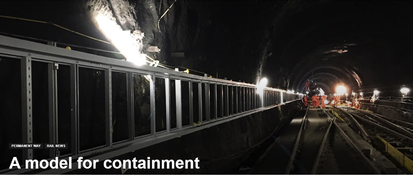
Cable Support & Containment
-
Special thanks to Paul Darlington from Rail Engineer for kind permission to republish this article
MITA Powered by WIBE is a major multi-national company, operating in a wide range of sectors including Rail, Utility, Data-centre, Renewable, Oil & Gas and Process industries – the company’s extensive Cable Support range includes a market-leading range of GRP Elevated Cable Troughing & Accessories which are designed and manufactured in the UK.
GRP elevated cable troughing is an especially useful containment system for rail.
Ground Level Troughing (GLT) is used in signalling and telecoms schemes for the cable connections to lineside equipment such as points, train detection, signals and radio sites.
However, in many places, GLT cannot be used due to the ground profile and steep embankments and cuttings. GRP is an ideal alternative for such locations and it is also essential for large current-carrying power cables, such as medium voltage 25kV trackside power cables.
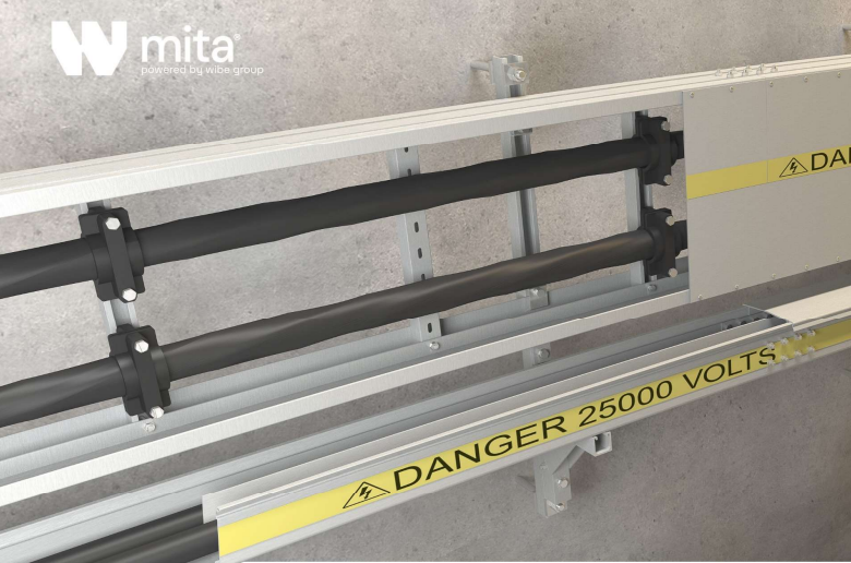
MITA WIBE is the leading “fit & forget” Cable Troughing & Management System manufactured in GRP with PADS Approval and specific material formula’s for trackside and tunnel applications on Network Rail infrastructure.

MITA are marker-leaders in the manufacture of GRP non-metallic troughing, GRP cable ladders, CABSYS cable trays, ducts, cable support channels and Fibastrut as the brand continues to lead the industry towards a sustainable future for a wide range of low (LV), medium (MV) and high voltage (HV) cable installation applications.
High quality manufacture
The MITA GRP is produced by pultrusion technology.
This uses a combination of unidirectional and cross-strand glass mat which is resin-impregnated and pulled through a hot die to produce a very solid, structurally sound profile with excellent mechanical rigidity.
Unlike some other troughing systems, MITA GRP does not contract or expand with heat causing the troughing route to distort. It is produced with a high quality of manufacture and modified by the use of additives to the resin, and with protection from ultra-violet light. The product is produced in either 3m or 6m lengths for easy transportation and installation.
MITA GRP is 70% lighter than steel and 90 times lighter than concrete; the cable trough is also corrosion resistant. It does not conduct heat and has excellent durability against adverse weather conditions. The rail cable management product offers excellent UV stability resulting in a cost-effective long-term solution.
The MITA GRP is provided in a wide range of trays, troughing and ladders which can support any type of cable – especially power and fibre cables which require a gentle bending radius. Unlike some competitors’ systems, MITA TM elevated troughing is provided with GRP support posts to increase its durability.
The troughing lids clip securely in place, providing cable theft protection. Further security can easily be added by installing stainless steel bands around the elevated route.
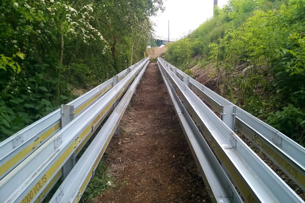
MitaTM GRP troughing in use on the East Coast Main Line
Network Rail approval
The MITA GRP elevated cable route has been fully approved by Network Rail under Certificate of Acceptance PA05/00442 issued in 2015 for use in locations unsuited to GLT. The Zero Halogen Low Smoke (ZHLS) version has also been approved for use in sub-surface stations and connecting tunnels.
Furthermore, the approval applies to a very impressive 42-page list of accessories, including bends, brackets, risers and transition/reducer pieces. Allowing connections to existing GLT cable routes, reducers are important and not always available in other cable containment systems.
London Underground has successfully used MITA GRP troughing. They were concerned that their sensitive signalling equipment was susceptible to contact by flakes of galvanisation from steel support systems and that their DC traction cabling system might create eddy currents within troughing ladders and supports if they were metallic.
MITA GRP troughing was chosen as it is non-magnetic and has non-conductive properties. The ZHLS version is also a requirement for London Underground’s sub-surface locations.
The cable containment system is not just used in rail, but has also been successfully employed in a wide range of industries including data centres, power industries, manufacturing, water treatment, food production, industrial buildings and oil and gas.
Working with GRP
Another particularly useful feature of the MITA GRP system is its ability to be integrated with the Bentley Raceway and Cable Management Building Information Modelling (BIM) tool.
This provides a complete layout, routing and material estimating function in a single, integrated system. It can be applied from the initial concept design through to detailed design and construction.
A user can create an accurate 3D model of the cable troughing route, making it easy to ensure that adequate space and clearances are available in confined locations, and for the detailed design and material requirements to be quickly and easily produced.
MITA GRP is a non-hazardous, inert product – the cable support system is lightweight and can be manually handled without difficulty, unlike concrete. In contrast to steel, GRP does not have to be deburred or given edge treatment before fitting, saving time and further reducing labour costs. During installation, any cutting, drilling, bonding and jointing can be easily undertaken and will not give rise to a hazardous situation, with any dust kept to a minimum.
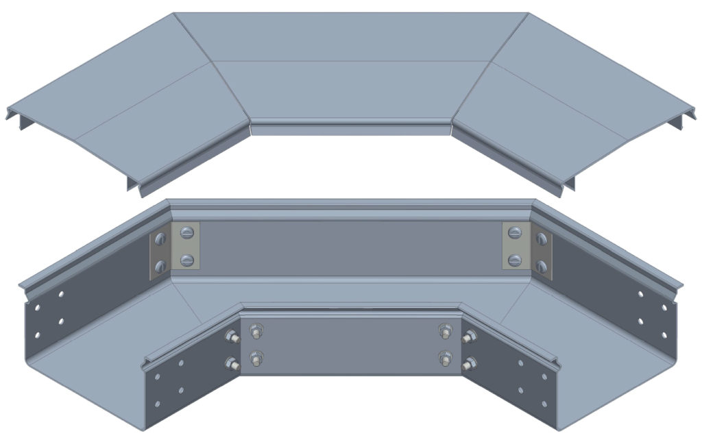
Sample Components of the MITA GRP Troughing System
Andrew Sillars, Contractor Specification Engineer, says: “Having supported the specification of Glass Reinforced Polymer cable containment since 2005, I have experienced its unique features such as light weight, long-life durability, no deburring, no earth bonding and many more. All these advantages of GRP Cable Containment support a cheaper, quicker and easier-to-install system that gives a true fit-and-forget solution.”
Original Source Rail Engineer Magazine article written by Paul Darlington
About Rail Engineer

Rail Engineer is the leading independent quality monthly magazine for engineers, project managers, directors and leading rail executive decision makers.
Besides publishing the latest up-to-date rail engineering news, our team of engineer writers report on the engineering and technical aspects of many of the major projects being undertaken day in, day out, above and below ground, and across the globe.
In the UK we work in close consultation with Network Rail, Docklands Light Railway and the Underground, where our team of rail engineers actively visit the project sites, meet project engineers and provide in-depth analysis on the engineering skills being used and the latest innovations.
From trams and fleet refurbishment to new rolling stock and high speed rail, the rail engineer reports on the engineering and environmental challenges for manufacturers and operators. Our engineers visit factories and depots, meeting with specialist engineers to bring you the latest engineering updates on all aspects of rolling stock, whether onboard technology or mechanical enhancements focussing on safety, energy and the passenger experience.
To Subscribe Click Here
RAIL ENGINEER MAY / JUNE 2021
View the latest edition below or click the following link where the original The Trackside Conduit Article can be found https://www.railengineer.co.uk/rail-engineer-may-june-2021-hs2s-largest-bridge-decarbonising-scotland-and-piccadilly-line-trains/
Paul Darlington joined British Rail as a Trainee Telecoms Technician in September 1975. He became an instructor in telecommunications and moved to the telecoms project office in Birmingham, where he was involved in designing customer information systems and radio schemes. By the time of privatisation, he was a project engineer with BR Telecommunications Ltd, responsible for the implementation of telecommunication schemes included Merseyrail IECC resignalling.
With the inception of Railtrack, Paul moved to Manchester as the Telecoms Engineer for the North West. He was, for a time, the Engineering Manager responsible for coordinating all the multi-functional engineering disciplines in the North West Zone.
His next role was Head of Telecommunications for Network Rail in London, where the foundations for Network Rail Telecoms and the IP network now known as FTNx were put in place. He then moved back to Manchester as the Signalling Route Asset Manager for LNW North and led the control period 5 signalling renewals planning. He also continued as Chair of the Safety Review Panel for the national GSM-R programme.
After a 37-year career in the rail industry, Paul retired in October 2012 and, as well as writing for Rail Engineer, is the Managing Editor of IRSE News.
Thorne & Derrick are leading Specialist Distributors & Stockists of LV, MV & HV Cable Installation, Jointing, Substation & Electrical Equipment to the Rail industry.
RAIL CABLE ACCESSORIES, ELECTRIFICATION
& INSTALLATION EQUIPMENT
Thorne & Derrick stock and distribute an extensive range of 400V-33kV Rail Cable Accessories & Power Distribution Systems including feeder pillars to contractors undertaking Low Voltage Power Distribution, HV Electrification & Substations, DC Traction & Networks, OLE and Track Feeder Cable Renewals – complete range of Network Rail PADS approved track terminations, cable joints, cable repair and connection products up to 25kV, including 3M Cold Shrink, Pfisterer CONNEX and Nexans Euromold products.

Cable Joints, Terminations & Connections | Distributors & Stockists for 3M Cold Shrink | Nexans Euromold | Pfisterer CONNEX
ELLIS Solus Single Cable Clamps For Non Metallic Market
July 6th, 2021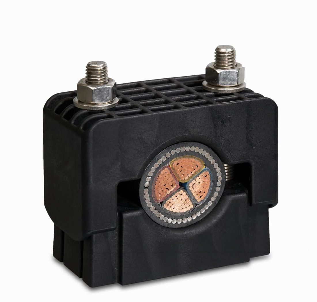
Non Metallic Single Cable Clamps
Ellis Solus Single Cable Clamps for Cleating Cables
Ellis Patents have boosted the strength of their cable clamps and cleats range with the launch of Solus single cable clamps. This range of non-metallic single cable clamps are suitable for cables from Ø25 to Ø75mm. Designed, developed and manufactured in-house by Ellis, Solus cable clamps are made from a high strength, glass-filled nylon and joins Trident – a trefoil clamp – as part of their expanding non-metallic product range.
Single Cable Clamps
Features
- Short circuit & mechanically tested in accordance with IEC61914
- Cleats manufactured from high grade heat stabilised polymer
- Suitable for indoor, outdoor and harsh environments
- Long design life
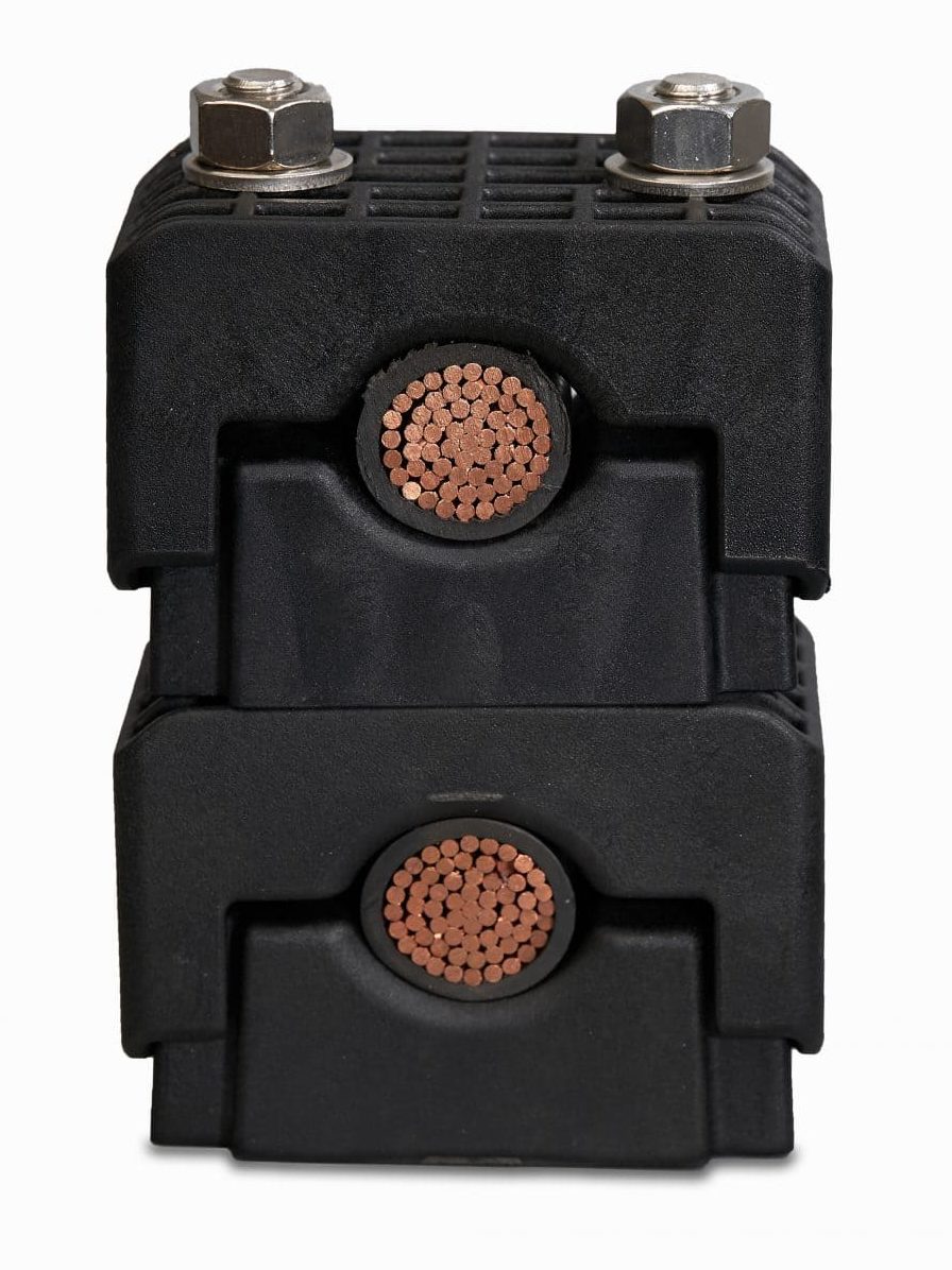
- Easily stacked cable clamps for multiple cables and circuits
- Large cable range (fewer clamps sized to stock)
Danny Macfarlane, Managing Director of Ellis Patents, said: “Non-metallic cable cleats have been very popular in mainland Europe for many years, and their use is now growing swiftly in the UK and many of the export markets we operate in around the world.”
“Their benefits are numerous but key is the fact that they have extremely long lifespans meaning the cleats can be used practically anywhere, including in extremely harsh environments.”
The reason for Solus’ extremely long lifespan is that the glass filled nylon material used is a high-grade engineering polymer. The new range of cable clamps is also fully stackable, meaning additions to cable runs can be made without having to disturb any cables already installed. Solus also features different mounting options that enhance its installation versatility; and because the product can accommodate a wide cable range, customers can stock small numbers of units to cover a wide range of cable sizes.
“Innovation is very much at the heart of everything we do, and Solus is the latest in a long line of new and improved cable management products to have come out the Ellis Patents Innovation Hub here in Rillington,” added Danny.
Key to Ellis’ ability to innovate is its ability to take products from initial ideas through to IEC61914:2015 compliant products; with its in-house Innovation Hub incorporating 3D printers, FEA analysis and a fully equipped testing laboratory.
Solus Single Cable Clamps
Specification

Ellis Solus Single Cable Clamps – Dimensions
| Ellis Solus Part Number | SL25-38GFN | SL36-52GFN | SL49-75GFN |
| Cable Range Min ∅ (mm) | 25 | 36 | 49 |
| Cable Range Max ∅ (mm) | 38 | 52 | 75 |
| Liner Size (mm) | 3 | 3 | 3 |
| Cable Range with Liner Min ∅ (mm) | 19 | 30 | 43 |
| Cable Range with Liner Max ∅ (mm) | 32 | 46 | 69 |
| Dimensions W (mm) | 100 | 116 | 138 |
| Dimensions H (mm) | 80 | 95 | 124 |
| Dimensions D (mm) | 60 | 77 | 77 |
| Dimensions A (mm) | 24 | 24 | 26 |
| Dimensions P (mm) | 60 | 75 | 95 |
| Dimensions ∅ | M12 | M12 | M12 |
| Weight (g) | 290 | 370 | 493 |
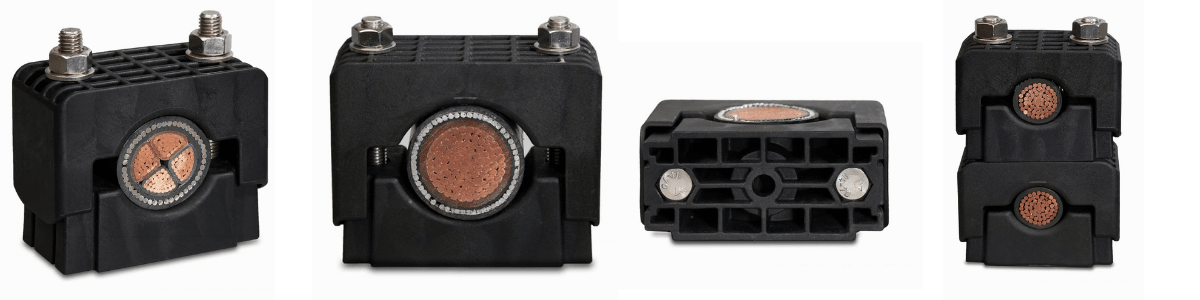
ELLIS Solus Cable Clamps
Further Reading
- IEC 61914 – Cable Cleats & Short Circuit Protection Calculations
- Fire Resistance & Cable Cleats – Surviving Fire, Flame & Extreme Heat
- Triplex Cleats – Selection Guide for Cleating 11kV BS7870 Part 4.10 Cables
- Stainless Steel Cable Cleats – Preventing Galvanic Corrosion Of Cable Fixings
- Ellis Patents Cable Cleats & Cable Basket Tray for Securing High Fault Level Cables
- Stainless Steel Cable Cleats v Ties – The Myths Debunked By Ellis Patents
THORNE & DERRICK
Thorne & Derrick are national distributors of LV, MV & HV Cable Installation, Jointing, Substation & Electrical Equipment – servicing businesses involved in cabling, jointing, substation, earthing, overhead line and electrical construction at LV, 11kV, 33kV, 66kV and EHV. Supplying a complete range of power cable accessories to support the installation and maintenance of low/medium and high voltage power systems:
- Slip-on Cable Terminations
- Cold-shrink Cable Terminations
- Heat-shrink Cable Terminations
- Cable Joints – Heat & Cold-shrink
- Separable Connectors (Euromold)
- Surge Arresters & Switchgear/Transformer Bushings
Key Product Categories: Duct Seals | Cable Cleats | Cable Glands | Electrical Safety | Arc Flash Protection | Cable Jointing Tools | Cable Pulling | Earthing | Feeder Pillars | Cable Joints LV | Joints & Terminations MV


Ellis Patents Vulcan, Atlas & Emperor Cable Cleats
Quad Cable Cleats By CMP
June 30th, 2021 CMP Launches
New Quad Cable Cleat Range
Leading cable gland and cable cleat manufacturer, CMP Products, has launched its new quad cable cleat range ‘Saturn’ (QSDSS), which allows cables to be safely installed in quad formation. Designed and developed by CMP’s in-house R&D team, the Saturn Quad cleat has a market-leading high short circuit rating of 152kA and has undergone stringent third party testing and certification to produce one of the strongest cleats and clamps of its kind.
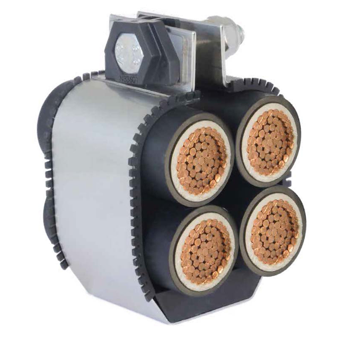
Quad Cable Cleats – CMP Saturn
CMP Cable Cleats
All of CMP’s cable cleats are manufactured with safety as a priority for both end-user and project infrastructure. The Saturn cleats safely restrain single cables in quad (also known as quadrafoil or quatrefoil) formation, whilst protecting the integrity of the cables and cable management system in the event of a short circuit fault condition.
The new quad cable cleat range has a compact design for space constrained-projects and is manufactured in the UK using 316L stainless steel. This provides superior strength and excellent corrosion resistance, making the quad cleat suitable for some of the harshest environments.
Designed to restrain cables across a range of industries including datacentres, rail, energy and more, the Saturn has been third party certified in accordance with IEC 61914:2015.
The Venus has a high short circuit rating of 135kA and can be installed in a range of applications where quadruplex cable is fitted. CMP has also developed the ‘Venus’ (QPSS) cable cleat, which is manufactured with an integrated C-clamp and bolt; providing installers with versatility of installation.
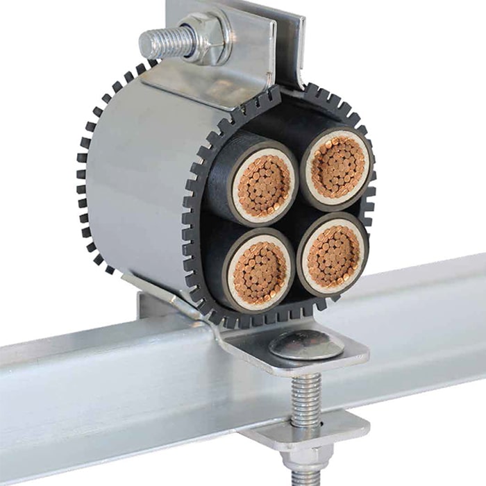
Quad Cable Cleats – CMP Venus
Lee Frizzell, Technical Director at CMP said: “In a space-sensitive but safety-conscious industry, the Saturn series offers a compact solution, whilst maintaining an incredibly high level of restraint, demonstrated by robust third-party testing.
“We have listened to our customer’s needs, producing a cable cleat that provides both safety and reliability. The demand for cable cleats is constantly growing as their essential role in cable management systems becomes increasingly recognised.”
LV, MV & HV Jointing, Earthing, Substation & Electrical Eqpt
Thorne & Derrick International are specialist distributors of LV, MV & HV Cable Installation, Jointing, Duct Sealing, Substation & Electrical Equipment – servicing UK and global businesses involved in cable installations, cable jointing, substation, overhead line and electrical construction at LV, 11kV, 33kV and EHV.
THORNE & DERRICK Product Categories: Duct Seals | Cable Cleats | Cable Glands | Electrical Safety | Arc Flash Protection | Cable Jointing Tools | Cable Pulling | Earthing | Feeder Pillars | Cable Joints LV | Joints & Terminations MV HV
Ellis Patents Engineer Change In Cable Management Market
May 11th, 2021
The following article has been republished from Ellis Patents, whereby Managing Director Danny Macfarlane discusses the rapid technological development in the cable management market.
According to Macfarlane, one key change this has led to is that standard product ranges now form the backbone of a far more flexible product offering. He talks to ECN.
When I first joined Ellis Patents in 2003, we very much had standard product ranges, which specifiers selected from according to their project requirements,” says Danny. “We still have these ranges today, and the likes of our Emperor and Vulcan+ cable cleats remain our bestsellers, but alongside them we have a slew of new, innovative products that have been developed as a result of a major shift in the way the market operates; which in itself has been enabled by technological development.”
Ellis Patents Vulcan, Atlas & Emperor Cable Cleats
In the last few years alone Ellis Patents has designed, developed and manufactured a completely new product for a major Siemens offshore wind project; solved installation headaches with bespoke solutions for Balfour Beatty; and consigned a major health and safety issue for National Rail to history with a product that went on to win a number of innovation awards.
The Siemens job was the first of these projects, with the company going to Ellis Patents with a need for a new product during a live project situation. The challenge was to develop a way of feeding, and then restraining, seven 117mm diameter cables along a specified route within a fabricated structure that featured a significant number of twists and turns.
Ellis Patents Cable Guide Clamp
The Cable Guide Clamp that was designed, developed and manufactured in response not only solved Siemen’s problem, it also secured an order that wouldn’t have been won had the company been relying solely on its standard product offering. And Ellis Patents didn’t stop with that one project, the Cable Guide Clamp has since been developed into a full range that regularly secures orders from around the world.

Ellis Patents Cable Guide Clamp
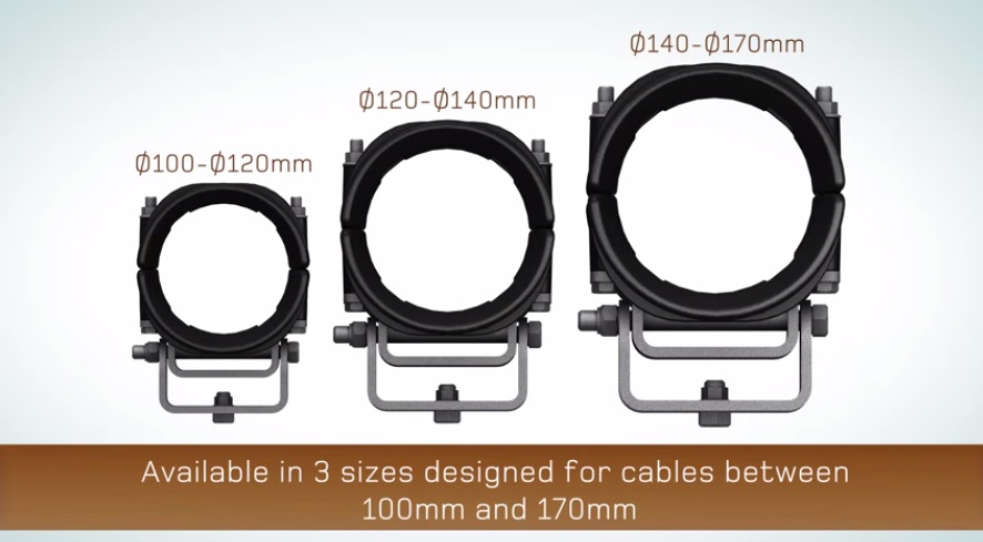
The Ellis Cable Guide Clamp is designed to be installed in place of rollers along the HV cable route where the cable length is pushed and pulled through to its final destination.
“Our ability to deliver these innovative bespoke solutions, some of which were done in live project situations, is something we’re immensely proud of,” says Danny.
“But without the technology we simply wouldn’t have been able to turn our ideas into fully functioning products in such pressurised, time-sensitive situations.
“Traditionally, creating a production ready prototype would have required the development of injection moulding tools, which involved significant investment in time and resource, and typically took six to eight weeks to manufacture. And once received only small changes to the tools were feasible, meaning any major alterations could add another six to eight weeks to the already lengthy process.
“Now, thanks to 3D CAD and rapid prototyping 3D printing, we can take products from an idea in a brainstorm to a fully functional, production ready prototype in less than a fortnight – something we have done on a number of occasions. And it’s a combination of the growing availability of rapid product development technology and ever-growing levels of in-house engineering expertise amongst manufacturers that has led to such significant change in the market.”

Siemens, for example, didn’t go to Ellis Patents with its complex installation issue because it saw the company as solely a manufacturer of standard products. It was because Ellis had the in-house expertise and technological capacity to solve its problem within the confines of an extremely tight time frame. And it’s this kind of expertise that is playing an ever more important role in the cable management market – in particular amongst those manufacturing cable cleats.
“Projects are often far from straightforward and installation and maintenance issues regularly arise, so having the people and the in house technology to be able to solve problems; firstly on paper and then with an adapted or wholly bespoke product; is now as important as that strong standard product range”, concludes Danny.
THORNE & DERRICK
Thorne & Derrick are national distributors of LV, MV & HV Cable Installation, Jointing, Substation & Electrical Equipment – servicing businesses involved in cabling, jointing, substation, earthing, overhead line and electrical construction at LV, 11kV, 33kV, 66kV and EHV. Supplying a complete range of power cable accessories to support the installation and maintenance of low/medium and high voltage power systems:
- Slip-on Cable Terminations
- Cold-shrink Cable Terminations
- Heat-shrink Cable Terminations
- Cable Joints – Heat & Cold-shrink
- Separable Connectors (Euromold)
- Surge Arresters & Switchgear/Transformer Bushings
Key Product Categories: Duct Seals | Cable Cleats | Cable Glands | Electrical Safety | Arc Flash Protection | Cable Jointing Tools | Cable Pulling | Earthing | Feeder Pillars | Cable Joints LV | Joints & Terminations MV
High Voltage Cable Cleats | Cables, Tunnels & Supporting HV Cables
May 4th, 2021
High Voltage Cable Cleats (HV EHV 132kV 275kV 400kV Cables) – Ellis Patents Centaur
High Voltage Cable Tunnel Cleats
275-400kV
As a result of the increasingly congested and over populated nature of our major cities, high voltage cable tunnels are fast becoming the preferred option for delivering electrical power – most notably because they provide a means of carrying large HV cables in a non-intrusive manner.
Andy Booth, Business Development Manager of leading cable cleat manufacturer, Ellis Patents talks to Electrical Review about a paper the company co-presented at the recent CIGRE Session in Paris, which focused on the issues concerning the clamping and supporting of HV cable systems in underground cable tunnels.
Many of the leading utilities companies are currently investing heavily in HV cable tunnels, and to give some idea of the scale of this investment it’s worth highlighting some of the proposed cable tunnels in London are 3m in diameter and up to 25km long.
Furthermore, the level of investment in new HV cable installations is likely to grow substantially over the next few years due to the fact many of the UK’s existing fluid filled 275kV and 400kV HV cable circuits are reaching the end of their original design life and will need to be replaced with new XLPE circuits.
As a rule of thumb, these HV single core cable systems are installed in a vertical flexible arrangement. This means the cables are supported, generally by cable cleats, at intervals of between 5 and 8.5 metres and allowed to sag in between.
This cable sagging allows the cables to take up thermal expansion and contraction in steady state conditions without the exertion of large thermo-mechanical forces. During load cycles the thermo-mechanical thrust developed by the cable conductor and sheath in an axial direction needs to be constrained by the cable cleats without damaging the cable oversheath.
In the case of short circuit faults and lightning strikes, the resulting high fault currents flowing through the cable will result in large lateral electro-mechanical forces between cores, which cause the cables to shake violently.
During these conditions accelerated sidewall pressures are experienced on the cable at the fixing points, which can compromise the integrity of not just the cleats, supports, clamps and the cable, but the entire HV cable network.
Amazingly, and despite the huge amount of theories, standards and literature regarding fault protection, very little attention is given to arguably the single most important piece of equipment in any fault protection system – the cable cleat.
Yes, IEC61914:2009 describes the appropriate requirements for cable cleats for electrical installations, but this only allows the use of 600V – 1kV cables in a series of tests to confirm the resistance to electro-magnetic forces.
Until now, methods for supporting large HV cables at fixed points have been designed on a project by project basis, but there have been no tests or related publications to determine how these HV cable fixings should perform in the event of a fault. Therefore, our intention when starting work on this project was simple – we wanted to develop a standard product that would provide adequate fault protection for all HV cable installations.
Rationale for appropriate fixings for power cable systems
The operating time for a typical breaker is generally between 3 and 5 cycles, which is equivalent to 0.06 – 0.1 seconds on a 50Hz system. Exceptionally quick relays may operate at 1.5 cycles. However, when considering three-phase faults and the instance of the peak forces, the time frame will be a quarter of a cycle or 0.005 seconds.
On the occurrence of a fault the highest repulsive force is proportional to the square of the peak short circuit current. This is then followed by a residual, pulsating, oscillating stress at a frequency of twice the operating frequency, known as the fault RMS. However, it is accepted that the forces at the peak of the fault are the highest, the most instantaneous, and in turn the most destructive, when considering system protection.
Recommendations for the calculation of short circuit currents are given in the IEC 60909:2001 series. For three phase short circuit faults the most severe repulsive force for flat spaced (horizontally or vertically) cables is experienced in the central phase due to the oscillating effects of mutually induced forces by the outside phases. For trefoil installed cables an equal force (at peak) is experienced in all three phases due to the symmetry.
Further consideration should also be given to the linear stresses along the actual conductor. It is common with cable installation assessments to use the calculation method simulating a bar fixed at both ends, thus determining the transverse deflection rate due to electro-magnetic forces during a fault. Further consideration, as a result of the instantaneous forces during a fault, is the effect of the surface pressure from the moving cables and its effect on the inner loop of the cleat itself.
The time duration for short circuit faults, such as 1 or 3 seconds, which is often specified by clients or in installation specifications, is often misinterpreted with respect to the duration of an actual short circuit fault. The 1s or 3s requirement quoted is the thermal withstand characteristic of the cable and considers conductor cross section and its ability to carry a level of current and therefore heat.
Design Criteria for HV Cable Saddles and Cable Straps
A longitudinal ‘saddle’ type of design, rather than the traditional cable clamp design tends to be best suited to this type of installations. Firstly, the cable saddle should be able to support the weight of the cable in its final installed position – and remember a 2500mm² copper conductor, lead sheathed cable can weigh almost 50kg per metre.
If we assume an 8m fixing distance, then the cable saddle must be able to support 4m (200kg) on one side and 4m on the other side, without deflecting or changing its original profile. Furthermore, the longitudinal saddle must also be radiused along its length to ensure the cable is adequately and safely supported. Various cable construction types affect the radius of the installed cables. For example a lead sheathed, copper conductor cable will have considerably different characteristics to an aluminium sheathed, aluminium conductor cable. The saddle manufacturer must ensure their product design matches this specific cable sag radius on any particular project.
It is undesirable for a cable to be in contact with any sharp edge of a cable cleat. To alleviate the problems various steps can be taken: All sharp edges must be removed as a matter of course from any face which may come into contact with the cable, either during installation, or when the cable is in its final, fixed position.
Generally, the base portion of the cable saddle for this type of installation is a minimum of 600mm long. As the cable is installed over the top of this 600mm long ‘beam’ it becomes curved when sagged. It is essential that the 600mm long ‘base section’ is also curved along its entire length, to ensure support is given to the cable over an area which is as large as possible. On each end of this curved ‘saddle’ section, as the cable leaves the saddle, an additional ‘flare’ should be added to further reduce the possibility of the cable being in contact with a defined edge, and therefore becoming damaged.
Once these general rules have been applied to an initial cleat concept, the actual cleat spacing and installation sag can be calculated.
Short Circuit Testing of a HV Cable Saddle Installation
There is very little empirical research, or cited publications with regard to short circuit testing cable fixings for HV cables. That said, major utility groups around the world use National Grid in the UK for technical expertise and knowledge and so it seemed sensible to use the technical specifications of National Grid as the basis for a series of live short circuit tests.
These tests were carried out at KEMA, an internationally recognised testing station in The Netherlands. The design of the test rig corresponded to the worst case scenario for the peak forces, and 8.4m fixing centres and a phase to phase spacing of 500mm was selected. If the calculation methods from IEC 61914:2009 are employed the maximum theoretical forces between each cleat can be shown as follows:
For a 2 phase fault:
F = 0.2 x 157.5² = 9922.5N/m or 9.923kN/m
0.5
The figure of 157.5 was obtained by using a multiplication factor of 2.5 on a 63kA RMS. This was the theoretical calculation used to obtain the appropriate peak force levels of the fault.
Post Test Cable Examinations
Immediately after the tests were completed and the cables were still in position, an electrical test was performed on each individual cable. Each cable sample satisfactorily withstood a 5kV direct voltage, applied between the lead sheath and the earthed conductive screen for one minute without breakdown or incident.
This procedure follows the requirements of ENA C55/4.
Upon dismantling the test rig a 1m section of cable was identified adjacent to each saddle and each intermediate strap (500mm each side of the saddle or clamp), and cut away for later examination. For each 1m length the following aspects were examined in great detail: Outer jacket over sheath, lead sheath, copper wire screen, lead sheath, and the interior surface core screen.
There were no features or defects attributable to the cleats or intermediate straps. Some features attributable to manufacturing and/or handling of the cable were seen, but as they were independent of the position of the cable cleats, it was evident that they were not due to the presence of the cleats. In any case these features were not of such a severity to compromise the performance of the cable.
Conclusion
With HV power cable installations becoming ever more commonplace, it was absolutely imperative that a tried, tested and trusted means of ensuring these cables remain intact and working during a short circuit situation was available to the industry. The Centaur saddle cleat that we developed as a result of this research has certainly been enthusiastically welcomed and is currently being installed in a major HV cable installation in the UK.
That said, from an industry perspective, there is still a long way to go. It seems that every new type of HV cable and accessory seems to be tested to a known standard with the exception of the cable cleat. However, now that a precedence has been set by our research and development it should follow that every cable saddle, cleat, strap or clamp that is to be used on a flexibly installed, HV, underground system should be fully and independently tested to meet, or exceed, the requirements of the specific project. Furthermore, all engineers in the field need to become ever more aware of the importance of cable fixings.
A full copy of the CIGRE session paper is available upon request.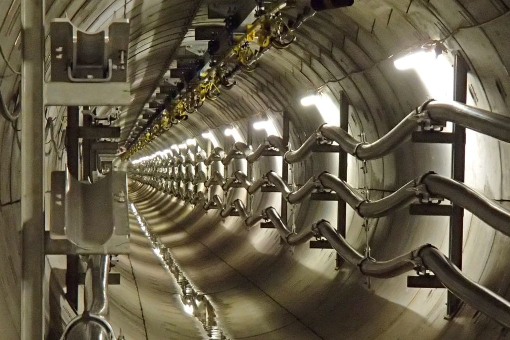
Thorne & Derrick
T&D are Specialist Distributors to UK Distribution Network Operators (DNO’s), NERS Registered Service Providers, ICP’s and HV Jointing Contractors of an extensive range of LV, MV & HV Jointing, Earthing, Substation & Electrical Eqpt – this includes 11kV/33kV/66kV joints, terminations and connectors for both DNO and private network applications.
Contact our UK Power Team for competitive quotations, fast delivery from stock and technical support or training on all LV-HV products.
Key Product Categories: Duct Seals | Cable Cleats | Cable Glands | Electrical Safety | Arc Flash Protection | Cable Jointing Tools | Cable Pulling | Earthing | Feeder Pillars | Cable Joints LV | Joints & Terminations MV HV
➡ Read: Thorne & Derrick Announce Distribution Agreement & Contract With Nexans


