

Cable Cleats
Solar Farms Replace Nylon Cable Ties With Metal Cable Ties
May 26th, 2020
Solar Farms Replace Nylon Cable Ties With Metal Cable Ties
BAND-IT Ball-Lok Metal Cable Ties
Essential. Everywhere. Together.
The BAND-IT Ball-Lok range of stainless steel cable ties provide fast and reliable bundling of LV MV HV cables for maximum strength, reliability and clamping of cables.
The corrosion resistant stainless cable steel ties with self-locking design are used to bundle, tie or fasten cables in both onshore and offshore locations including industrial, substation and hazardous area locations with potentially explosive atmospheres.
Several developers and installers of solar farms specify BAND-IT cable ties for a better solution that matches the lifespan of the photovoltaic panels and replaces nylon cable ties with Ball-Lok cable ties as part of their cable management portfolio.
The decision has been by many solar farms to replace the nylon ties with BAND-IT metal cable ties to reduce maintenance and costly failures.
Currently there are over 2,000 solar farms (over 10 MW) planned throughout the United States. The average livespan of a photovoltaic panel is 20 years, which is much longer than the lifespan of a traditional nylon cable tie, especially in extreme heat and UV exposure typically found in high producing solar areas.

BAND-IT Ball-Lok Cable Ties
The BAND-IT Edge
- Ball-Lok cable ties are tested and hold firm in extreme heat
- No UV degradation of stainless steel cable ties
- Simple hand tools minimize installation variation
- ISO 9001 and ISO 14001 Certified manufacturing
BAND-IT Ball-Lok Metal Cable Ties
Product Features
- Cable ties are available coated or uncoated
- Lightweight, high strength to size ratio
- Smooth band edges won’t damage cable sheath
- Installation tool provides consistent tensioning
BAND-IT KE CABLE TIES
BALL LOK STAINLESS STEEL – UNCOATED
The following selection tables shows the complete range of BAND-IT Ball-Lok cable ties – manufactured from type 304 or 316 stainless steel:
| BAND-IT Order Code | Coated / Uncoated | Cable Tie Material | Width | Length | Max Dia Single Wrap | Min Loop Tensile Strength (lbs) | Package Quantity | Package Weight | ||||
| in | mm | in | mm | in | mm | lbs | kg | |||||
| KE1118 | Uncoated | 304 SS | 0.180 | 4.6 | 5.9 | 150 | 1.2 | 30 | 200 | 100 / Bag | 0.4 | 0.2 |
| KE1128 | Uncoated | 304 SS | 0.180 | 4.6 | 7.9 | 201 | 2.0 | 50 | 200 | 100 / Bag | 0.6 | 0.3 |
| KE1138 | Uncoated | 304 SS | 0.180 | 4.6 | 10.2 | 259 | 2.7 | 69 | 200 | 100 / Bag | 0.7 | 0.4 |
| KE1148 | Uncoated | 304 SS | 0.180 | 4.6 | 14.2 | 360 | 4.0 | 102 | 200 | 100 / Bag | 0.9 | 0.5 |
| KE1158 | Uncoated | 304 SS | 0.180 | 4.6 | 20.4 | 520 | 6.0 | 152 | 200 | 100 / Bag | 1.3 | 0.6 |
| KE1168 | Uncoated | 304 SS | 0.180 | 4.6 | 26.8 | 679 | 8.0 | 203 | 200 | 100 / Bag | 1.8 | 0.8 |
| KE1178 | Uncoated | 304 SS | 0.180 | 4.6 | 33.0 | 838 | 10.0 | 254 | 200 | 100 / Bag | 2.1 | 1.0 |
| KE1188 | Uncoated | 304 SS | 0.180 | 4.6 | 42.0 | 1067 | 12.0 | 305 | 200 | 100 / Bag | 2.4 | 1.1 |
| KE0118 | Uncoated | 316 SS | 0.180 | 4.6 | 5.9 | 150 | 1.2 | 30 | 200 | 100 / Bag | 0.4 | 0.2 |
| KE0128 | Uncoated | 316 SS | 0.180 | 4.6 | 7.9 | 201 | 2.0 | 50 | 200 | 100 / Bag | 0.6 | 0.3 |
| KE0138 | Uncoated | 316 SS | 0.180 | 4.6 | 10.2 | 259 | 2.7 | 69 | 200 | 100 / Bag | 0.7 | 0.4 |
| KE0148 | Uncoated | 316 SS | 0.180 | 4.6 | 14.2 | 360 | 4.0 | 102 | 200 | 100 / Bag | 0.9 | 0.5 |
| KE0158 | Uncoated | 316 SS | 0.180 | 4.6 | 20.4 | 520 | 6.0 | 152 | 200 | 100 / Bag | 1.3 | 0.6 |
| KE0168 | Uncoated | 316 SS | 0.180 | 4.6 | 26.8 | 679 | 8.0 | 203 | 200 | 100 / Bag | 1.8 | 0.8 |
| KE0178 | Uncoated | 316 SS | 0.180 | 4.6 | 33.0 | 838 | 10.0 | 254 | 200 | 100 / Bag | 2.1 | 1.0 |
| KE0188 | Uncoated | 316 SS | 0.180 | 4.6 | 42.0 | 1067 | 12.0 | 305 | 200 | 100 / Bag | 2.4 | 1.1 |
| KE1328 | Uncoated | 304 SS | 0.310 | 7.9 | 7.9 | 201 | 2.0 | 50 | 300 | 100 / Bag | 1.0 | 0.5 |
| KE1338 | Uncoated | 304 SS | 0.310 | 7.9 | 10.2 | 259 | 2.7 | 69 | 300 | 100 / Bag | 1.3 | 0.6 |
| KE1348 | Uncoated | 304 SS | 0.310 | 7.9 | 14.2 | 360 | 4.0 | 102 | 300 | 100 / Bag | 1.7 | 0.8 |
| KE1358 | Uncoated | 304 SS | 0.310 | 7.9 | 20.4 | 520 | 6.0 | 152 | 300 | 100 / Bag | 2.2 | 1.1 |
| KE1368 | Uncoated | 304 SS | 0.310 | 7.9 | 26.8 | 679 | 8.0 | 203 | 300 | 100 / Bag | 2.9 | 1.3 |
| KE1378 | Uncoated | 304 SS | 0.310 | 7.9 | 33.0 | 838 | 10.0 | 254 | 300 | 100 / Bag | 3.5 | 1.6 |
| KE1388 | Uncoated | 304 SS | 0.310 | 7.9 | 42.0 | 1067 | 12.0 | 305 | 300 | 100 / Bag | 4.6 | 2.1 |
| KE0328 | Uncoated | 316 SS | 0.310 | 7.9 | 7.9 | 201 | 2.0 | 50 | 300 | 100 / Bag | 1.0 | 0.5 |
| KE0338 | Uncoated | 316 SS | 0.310 | 7.9 | 10.2 | 259 | 2.7 | 69 | 300 | 100 / Bag | 1.3 | 0.6 |
| KE0348 | Uncoated | 316 SS | 0.310 | 7.9 | 14.2 | 360 | 4.0 | 102 | 300 | 100 / Bag | 1.7 | 0.8 |
| KE0358 | Uncoated | 316 SS | 0.310 | 7.9 | 20.4 | 520 | 6.0 | 152 | 300 | 100 / Bag | 2.2 | 1.1 |
| KE0368 | Uncoated | 316 SS | 0.310 | 7.9 | 26.8 | 679 | 8.0 | 203 | 300 | 100 / Bag | 2.9 | 1.3 |
| KE0378 | Uncoated | 316 SS | 0.310 | 7.9 | 33.0 | 838 | 10.0 | 254 | 300 | 100 / Bag | 3.5 | 1.6 |
| KE0388 | Uncoated | 316 SS | 0.310 | 7.9 | 42.0 | 1067 | 12.0 | 305 | 300 | 100 / Bag | 4.6 | 2.1 |
BAND-IT KE CABLE TIES
BALL LOK STAINLESS STEEL – COATED
| BAND-IT Order Code | Coated / Uncoated | Cable Tie Material | Width | Length | Max Dia Single Wrap | Min Loop Tensile Strength (lbs) | Package Quantity | Package Weight | ||||
| in | mm | in | mm | in | mm | lbs | kg | |||||
| KE0218 | Coated | 316 SS | 0.180 | 4.6 | 5.9 | 150 | 1.2 | 30 | 150 | 100 / Bag | 0.5 | 0.2 |
| KE0228 | Coated | 316 SS | 0.180 | 4.6 | 7.9 | 201 | 2.0 | 50 | 150 | 100 / Bag | 0.6 | 0.3 |
| KE0238 | Coated | 316 SS | 0.180 | 4.6 | 10.2 | 259 | 2.7 | 69 | 150 | 100 / Bag | 0.7 | 0.4 |
| KE0248 | Coated | 316 SS | 0.180 | 4.6 | 14.2 | 360 | 4.0 | 102 | 150 | 100 / Bag | 1.0 | 0.5 |
| KE0258 | Coated | 316 SS | 0.180 | 4.6 | 20.4 | 520 | 6.0 | 152 | 150 | 100 / Bag | 1.4 | 0.7 |
| KE0268 | Coated | 316 SS | 0.180 | 4.6 | 26.8 | 679 | 8.0 | 203 | 150 | 100 / Bag | 1.8 | 0.8 |
| KE0278 | Coated | 316 SS | 0.180 | 4.6 | 33.0 | 838 | 10.0 | 254 | 150 | 100 / Bag | 2.3 | 1.1 |
| KE0428 | Coated | 316 SS | 0.310 | 7.9 | 7.9 | 201 | 2.0 | 50 | 175 | 100 / Bag | 1.1 | 0.6 |
| KE0438 | Coated | 316 SS | 0.310 | 7.9 | 10.2 | 259 | 2.7 | 69 | 175 | 100 / Bag | 1.5 | 0.8 |
| KE0448 | Coated | 316 SS | 0.310 | 7.9 | 14.2 | 360 | 4.0 | 102 | 175 | 100 / Bag | 1.8 | 0.8 |
| KE0458 | Coated | 316 SS | 0.310 | 7.9 | 20.4 | 520 | 6.0 | 152 | 175 | 100 / Bag | 2.4 | 1.2 |
| KE0468 | Coated | 316 SS | 0.310 | 7.9 | 26.8 | 679 | 8.0 | 203 | 175 | 100 / Bag | 3.1 | 1.4 |
| KE0478 | Coated | 316 SS | 0.310 | 7.9 | 33.0 | 838 | 10.0 | 254 | 175 | 100 / Bag | 3.8 | 1.2 |

BAND-IT Ball Lok Stainless Steel Cable Ties In Use

BAND-IT Ball Lok Stainless Steel Cable Ties KE Range – Installation Tools
BAND-IT KE cable ties can be installed using BAND-IT K502 Ball-Lok Tool and BAND-IT KE922 Tensioning Tool.
For further information about cable ties for securing LV-HV cables (power, control and instrumentation), visit BAND-IT.

Tie Lok | Ultra-Lok | Ball-Lok | Multi-Lok | Reusable | Band & Buckles | Stainless Steel
Further Reading
THORNE & DERRICK SPECIALIST ELECTRICAL DISTRIBUTOR

The LV HV Specialists
Thorne & Derrick distribute the most extensive range of Cable Installation & Electrical Distribution Equipment to the renewable energy sector – we service UK and international clients working on underground cables, overhead lines, substations and electrical construction at 11kV and up to and EHV transmission and distribution voltages.
- Key Products: MV-HV Cable Joints & Terminations, Cable Cleats, Duct Seals, Cable Transits, Underground Cable Protection, Copper Earth Tapes, Cable Jointing Tools, Feeder Pillars, Cable Ducting, Earthing & Lightning Protection, Electrical Safety, Cable Glands, Arc Flash Protection & Fusegear.
- Distributors for: 3M Cold Shrink, ABB, Alroc, Band-It, Catu, Cembre, Centriforce, CMP, Elastimold, Ellis Patents, Emtelle, Furse, Lucy Zodion, Nexans Euromold, Pfisterer, Polypipe, Prysmian, Roxtec.

LV – Low Voltage Cable Joints, Glands, Cleats, Lugs & Accessories (1000 Volts)

MV HV – Medium & High Voltage Cable Joints, Terminations & Connectors (11kV 33kV EHV)

Cable Laying – Underground Cable Covers, Ducting, Seals & Cable Pulling Equipment
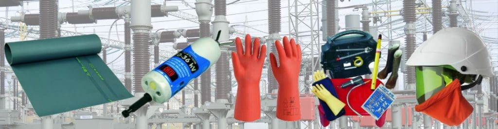
T&D, CATU Electrical Safety & Arc Flash Protection Specialists for SAP’s, Linesmen, Jointers & Electrical Engineers – Largest UK Stockist

High Voltage Cable Cleats for HV Cables from CMP
April 23rd, 2020

HV Cable Cleats
As part of its comprehensive cable cleat range, CMP offers a selection of high voltage (HV) cable cleats that are designed to safely restrain high voltage cable (s). CMP is able to provide cable cleats for any level of cable voltage; for example 3.3kV, 230kV or 1,000kV.
Manufactured from the highest quality materials, CMP’s HV cable cleat range has excellent corrosion resistance, strength and durability, making them suitable for use in the harshest of environments.
Designed and manufactured in accordance with the International Standard IEC 61914: Cable cleats for electrical installations, CMP cable cleats undergo rigorous short circuit testing.
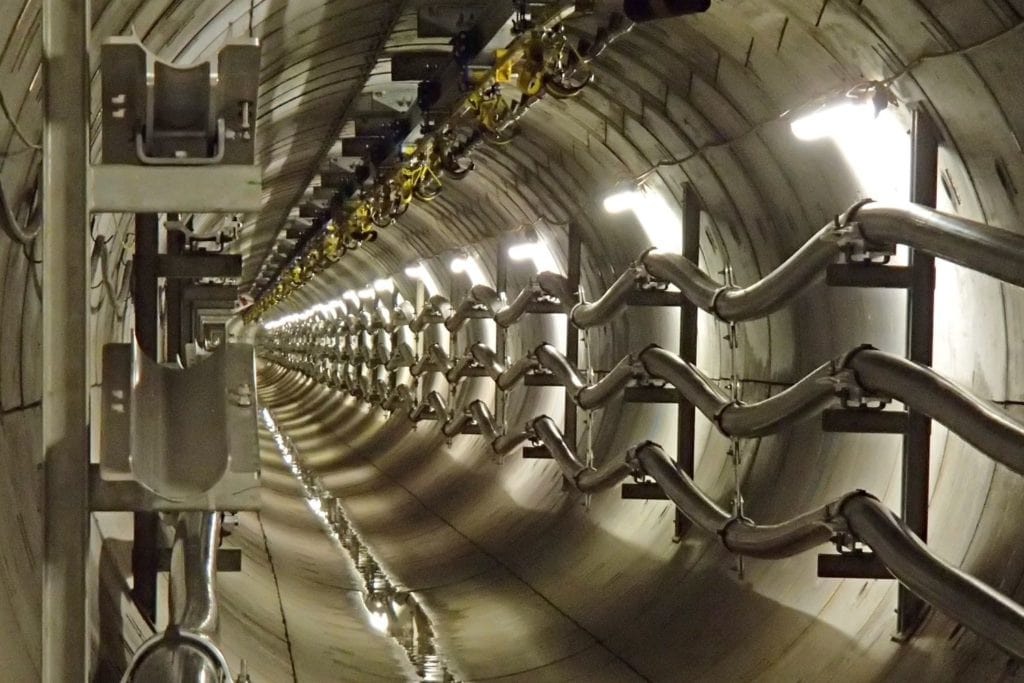
CMP designed two bespoke trefoil cable cleats for high voltage cable for the major, and highly technical Singapore Tunnel Project.
What standards does the range comply with?
All CMP high voltage cable cleats are third-party certified in accordance with the International Standard IEC 61914: Cable cleats for electrical installations, to ensure the securing and retention of cables without sustaining damage to the cable(s).
Where specific client requirements mean that the short circuit test parameters fall outside of the criteria laid out in IEC 61914; for example the customer specific size of cable to be tested is larger, or the number of cleats per test setup is smaller; then the test procedure and criteria of IEC 61914, and the customer’s test requirements, are both adhered to.
CMP has conducted numerous additional client specific tests, with certification obtained as required on a project specific basis.
What materials are used for CMP’s High Voltage Cable Cleats?
CMP’s high voltage cable cleats are manufactured from the highest quality 316L stainless steel to provide products with high creep strength and excellent corrosion resistance.
A selection of products within this range are also available in aluminium. The grades of aluminium we use are selected for their high corrosion resistance and superior tensile strength.
Cleats can be optionally powder coated – CMP offers standard Epoxy or Polyester powder coating. A polymer alloy coating which is UL94 V0 flame retardant, and Low Smoke and Fume Zero Halogen (LSF0H) is also available.
The polymer cleat liners supplied as standard are classified as Low Smoke and Fume Zero Halogen (LSF0H) and Phosphorus-Free.
Bespoke HV cable cleats for specific project requirements
CMP works with clients to design and manufacture bespoke cable cleat solutions to cater for specific project requirements. We can supply industrial products which do not require certification, designed to exact requirements.
We also offer a design service which includes all testing and third party certification of the products.
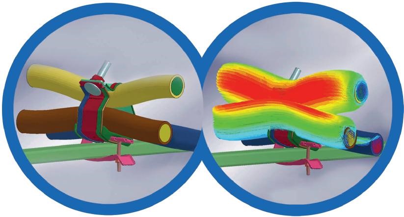
Using Finite Element Analysis (FEA) during the product design process, CMP’s dedicated cleat development team are able to model the stresses on cable cleats under short circuit situations, allowing them to make accurate predictions as to how products will perform when installed. This saves vast amounts of time in the early development and testing phases, reducing the overall lead time for our customers.
| Product Code | Description | |
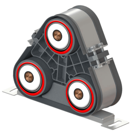 |
HVSS-EC | High voltage trefoil cable cleat with expanded cable centres. (Fixed and sliding base variants available) |
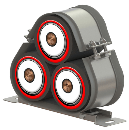 |
HVSS-CC | High voltage trefoil cable cleat with closed centres. (Fixed and sliding base variants available) |
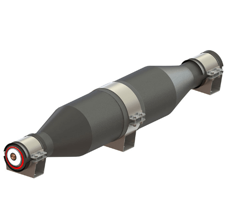 |
SHVSS-JSC | Single high voltage, stainless steel, joint support cleat |
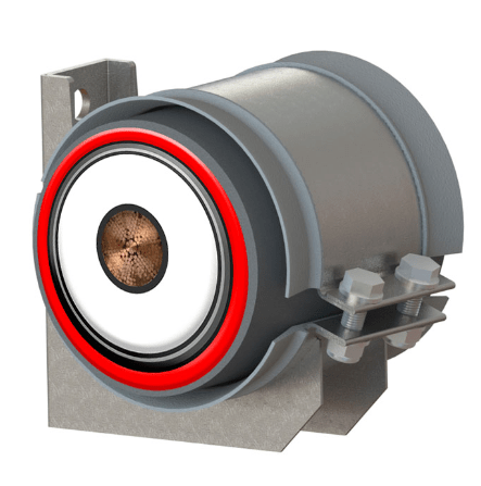 |
SHVSS-WM | Single high voltage wall mounted cleat |
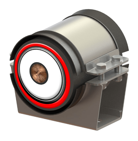 |
SHVSS | Single high voltage cable cleat |

LV, MV & HV Jointing, Earthing, Substation & Electrical Eqpt
Thorne & Derrick International are specialist distributors of LV, MV & HV Cable Installation, Jointing, Duct Sealing, Substation & Electrical Equipment – servicing UK and global businesses involved in cable installations, cable jointing, substation, overhead line and electrical construction at LV, 11kV, 33kV and EHV.
THORNE & DERRICK Product Categories: Duct Seals | Cable Cleats | Cable Glands | Electrical Safety | Arc Flash Protection | Cable Jointing Tools | Cable Pulling | Earthing | Feeder Pillars | Cable Joints LV | Joints & Terminations MV HV
Black C8 Wire Mesh Cable Tray for Hazardous & Aggressive Cable Containment from Pemsa
March 2nd, 2020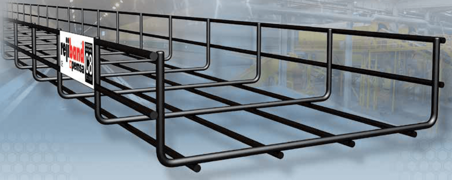
Black C8 Wire Mesh Cable Tray | Pemsa
-
Guest Information from Pemsa
Black C8
Wire Mesh Cable Tray
Pemsa has developed a high resistance coating for rejiband® wire mesh tray which provides an excellent resistance to corrosion in wet and aggressive environments.
High Corrosion Resistance
Demonstrated with more than 1000 hours in the neutral salt spray tests and obtained through a new manufacturing process that improves both the barrier effect against the aggressive media and the ability of self healing in damaged areas. With the result obtained in the neutral salt spray test, more than 850 hours, the corrosion resistance is classified as Class 8, according to Table 9 of the current standard BS EN 61537 trays.
BS EN 61537
This International Standard specifies requirements and tests for cable tray systems and cable ladder systems intended for the support and accommodation of cables and possibly other electrical equipment in electrical and/or communication systems installations. Where necessary, cable tray systems and cable ladder systems may be used for the division or arrangement of cables into groups.
Salt Spray Test Duration
| Class | Duration |
| 0 | – |
| 1 | 24 |
| 2 | 96 |
| 3 | 155 |
| 4 | 195 |
| 5 | 450 |
| 6 | 550 |
| 7 | 700 |
| 8 | 850 |

Duration (h) Salt Spray Chamber Chamber Test – acc. ASTM-B117
Certified High Resistance
rejiband® BLACK C8 has obtained the AENOR N Marking (Spanish Association for Standardization and Certification) and the certification IECEE CB Scheme of IEC (International Electrotechnical Commission), garanting the Class C8 of resistance against corrosion, with more than 1000 hours on the Salt Spray Test.
BETTER FEATURES THAN HOT DIP GALVANISED
Hot dip galvanised normally ranges from between 45 to 70 microns mean coating thickness, so it should be Class 5, 6, or 7, having a lower corrosion resistance than BLACK C8.
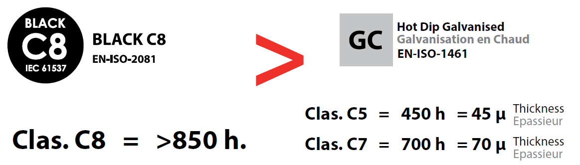
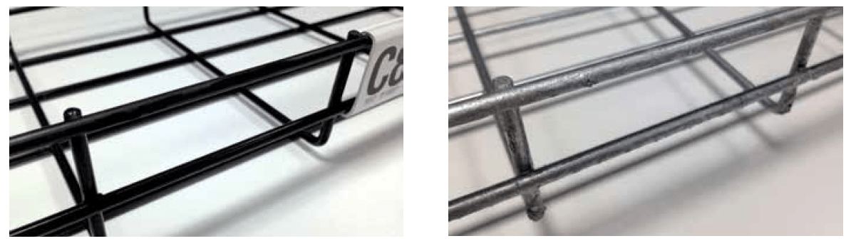
Aesthetic appearance
The smooth finish is much more aesthetic than that of hot dip galvanised.
- No sharp edges or ends
- No irregularities or areas with reduced thickness
- Black colour provides excellent aesthetics which are suitable for decorative applications, commercial facilities, false ceilings, etc.
Electrical continuity
This coating maintains the electrical continuity of rejiband®, complying with the requirements of BS EN 61537 standard for cable tray system with electrical continuity characteristics. This feature allows bonding to other exposed conductive elements and, in case of a fault, the evacuation of electrical currents to the earth.

The most appropriate coating for Data Centres
BLACK C8 coating avoids the emergence of the phenomenon of Zinc Whiskers, or loosening of filaments of zinc, which can be a serious problem within the electronics of clean rooms in Data Processing Centres.
Increased capacity for selfhealing, or self-repairing, of the protective layer
The characteristics of self-healing, or self regeneration, on scratches, minor defects or in the cutting of the wire, are remarkably better than that of the zinc.

Excellent ductility
It is possible to bend the the tray without causing any damage to the finish. These features retain the properties of flexibility and the forming of accessories with rejiband®, bends, level changes, in any format.
Environmentally Friendly
The BLACK C8 coating is manufactured in a process which significantly reduces energy consumption and waste generation over other coatings which consume more resources like hot dip galvanised.
Full Range of brackets and accessories
rejiband® BLACK C8, product range includes a complete catalogue of accessories and supports, providing a high corrosion resistance and a better visual aspect to the whole installation. This system offers the same corrosion resistance of Class C8 for everything, improving the performance of the system against aggressive environments and enhancing the performance of a hot dip galvanized finish, where accessories and brackets do not reach this classification. The system is complemented by the use of a black colour zinc spray that is suitable for the protection and aesthetic improvement of cut rods and possible damage caused during installation.
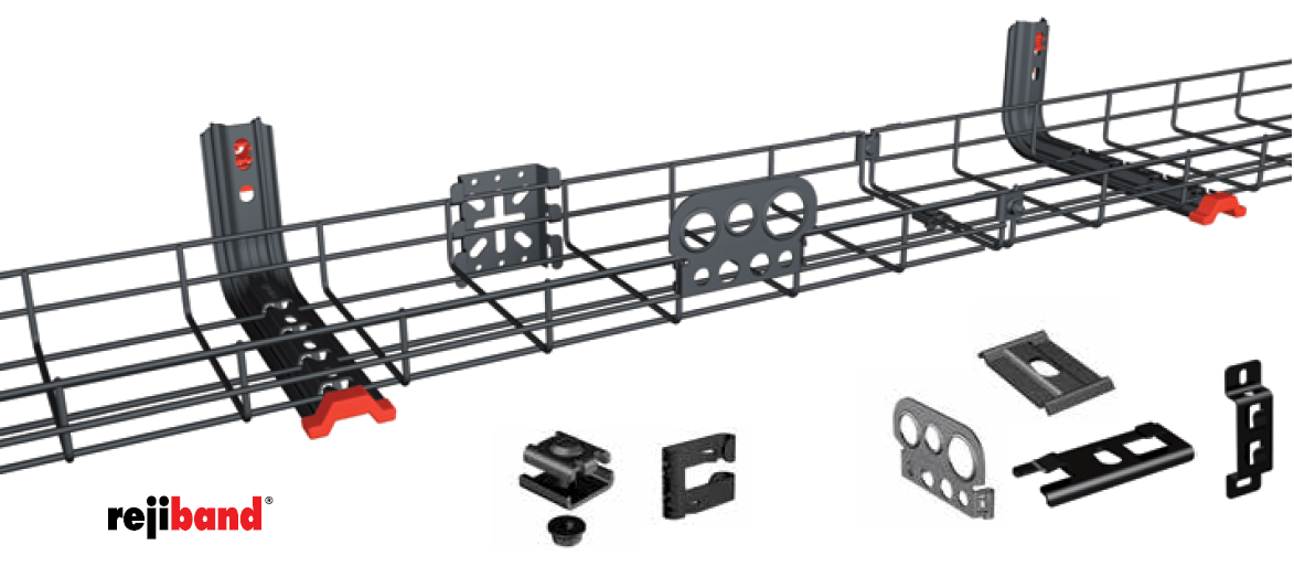
| Black C8 Wire Mesh Cable Tray Reference | Description | Pack (m) |
| 60282060 | REJIBAND 60×60 C8 | 24 |
| 60282100 | REJIBAND 60×100 C8 | 24 |
| 60282150 | REJIBAND 60×150 C8 | 24 |
| 60282200 | REJIBAND 60×200 C8 | 18 |
| 60282300 | REJIBAND 60×300 C8 | 12 |
| 60282400 | REJIBAND 60×400 C8 | 6 |
| 60282500 | REJIBAND 60×500 C8 | 6 |
| 60282600 | REJIBAND 60×600 C8 | 6 |
| 64080030 | CLICK CONNECTOR C8 | 30 |
| 64080035 | FAST CLICK JOINT C8 | 50 |
| 64080036 | FAST CLICK BASE JOINT C8 | 10 |
| 64080041 | SIDE JOINT PLATE C8 | 50 |
| 64080059 | SERRATED HEXAGON FLANGE NUT C8 | 50 |
| 64080060 | PART CLAMP C8 | 50 |
| 64080061 | REINFORCED JOINT CLAMP C8 | 50 |
| 64080072 | FAST CLIP C8 | 50 |
| 68000053 | BLACK Zinc Spray 400 ml | 1 |
| 67080030 | LUMINAIRE AND BOX SUPPORT C8 | 10 |
| 67080040 | CONDUIT GLAND BRACKET C8 | 10 |
| 67080043 | CLICK CENTRAL SUSPENSION M8/M10 C8 | 20 |
| 67080046 | CENTRAL HANGING PLATE M8/M10 C8 | 20 |
| 67080053 | SPLICE PLATE C8 | 10 |
| 67080143 | CLICK CENTRAL SUSPENSION M6 C8 | 20 |
| 62081060 | SIDE SUPPORT 60 C8 | 25 |
| 62086010 | MINI UNIVERSAL BRACKET C8 | 10 |
| 62086011 | UNIVERSAL BRACKET C8 | 10 |
| 62086020 | LIGHT DUTY CEILING SUPPORT C8 | 10 |
| 62086021 | LIGHT DUTY WALL SUPPORT C8 | 25 |
| 62086022 | BASE SUPPORT 60 C8 | 10 |

| Black C8 Wire Mesh Cable Tray Reference | Description | Pack (m) |
| 62081104 | OMEGA SPLUS BRACKET 100 C8 | 5 |
| 62081154 | OMEGA SPLUS BRACKET 150 C8 | 5 |
| 62081204 | OMEGA SPLUS BRACKET 200 C8 | 5 |
| 62081304 | OMEGA SPLUS BRACKET 300 C8 | 5 |
| 62081404 | OMEGA SPLUS BRACKET 400 C8 | 5 |
| 62081504 | OMEGA SPLUS PENDANT 500 C8 | 5 |
| 62081604 | OMEGA SPLUS PENDANT 600 C8 | 5 |
| 62082104 | OMEGA SPLUS CEILING BRACKET 100 C8 | 4 |
| 62082154 | OMEGA SPLUS CEILING BRACKET 150 C8 | 4 |
| 62082204 | OMEGA SPLUS CEILING BRACKET 200 C8 | 4 |
| 62082304 | OMEGA SPLUS CEILING BRACKET 300 C8 | 4 |
| 62082404 | OMEGA SPLUS CEILING BRACKET 400 C8 | 4 |
| 62085103 | MEDIUM DUTY CANTIL. R PLUS 100 C8 | 4 |
| 62085153 | MEDIUM DUTY CANTIL. R PLUS 150 C8 | 4 |
| 62085203 | MEDIUM DUTY CANTIL. R PLUS 200 C8 | 4 |
| 62085303 | MEDIUM DUTY CANTIL. R PLUS 300 C8 | 4 |
| 62085403 | MEDIUM DUTY CANTIL. R PLUS 400 C8 | 4 |
| 62085503 | MEDIUM DUTY CANTIL. R PLUS 500 C8 | 4 |
| 62085603 | MEDIUM DUTY CANTIL. R PLUS 600 C8 | 4 |
| 63082104 | OMEGA CHANNEL SPLUS 100 C8 | 10 |
| 63082154 | OMEGA CHANNEL SPLUS 150 C8 | 10 |
| 63082204 | OMEGA CHANNEL SPLUS 200 C8 | 10 |
| 63082304 | OMEGA CHANNEL SPLUS 300 C8 | 10 |
| 63082404 | OMEGA CHANNEL SPLUS 400 C8 | 10 |
| 63082504 | OMEGA CHANNEL SPLUS 500 C8 | 10 |
| 63082604 | OMEGA CHANNEL SPLUS 600 C8 | 10 |
APPLICATIONS

Tunnels & Industry

Photovoltaic & Shopping Centres

Waste Treatment Plants & Data Centres
LV, MV & HV JOINTING, EARTHING, SUBSTATION & ELECTRICAL EQPT
Thorne & Derrick International are specialist distributors of LV, MV & HV Cable Installation, Jointing, Duct Sealing, Substation & Electrical Equipment – servicing UK and global businesses involved in cable installations, cable jointing, substation, overhead line and electrical construction at LV, 11kV, 33kV and EHV.
Cable Cleats v Cable Strapping Bands | A White Paper by Panduit
November 21st, 2019
Panduit Cable Cleats For Short Circuit Protection
Cable Cleats v Cable Strapping Bands
-
A Whitepaper Republished Courtesy of Panduit -
by Chris Dodds | Sales Marketing Manager Thorne & Derrick
Cable Cleats v Cable Strapping Bands
Misconceptions
Recent articles in the industry suggest that a cable banding system is not capable of withstanding the electromechanical forces between the conductors in the event of a phase to phase fault. There is also a perception that a band type cleat product will cut the outer insulation of the cable under fault conditions.
This paper challenges these misconceptions and offers a more logical, engineered route to the correct specification of a cable fixing system. The reasoning is backed up and proven by independent third-party analysis and testing.
Traditional cable cleats started to appear in 1940’s and 1950’s predominantly in the U.K and Germany. These early cable fixing products were constructed from a variety of materials including timber, die cast aluminium and injection moulded polymers.
Due to the relatively weak or brittle mechanical properties of these materials the designs tended to be ‘over engineered’ to achieve the strength and performance required.
Figure 1

Figure 1. A Traditional Cable Cleat (Panduit 2-Hole Cable Cleat Used)
In more recent years, galvanised mild steel and 316 stainless steel options were developed which offered improved strength but still had a very bulky form factor. Early designs made in these materials offered a finished cable cleat which was twice the width and twice the height of the cable(s) being retained.
This was acceptable in single run applications e.g. when fastened sparingly to a wooden pole for utility applications, but when used in a cable ladder or tray application with multiple cable runs or within a substation where space and weight need to be carefully considered, the early designs did not meet requirements. Bulky cleat designs are not optimal.
However, recently introduced designs, materials and technologies have allowed Panduit to develop a high-end range of Strap Band products which meet or exceed the performance of a traditional cleat design when testing in accordance with IEC 61914:2015 by a third party lab. (Figure 2)
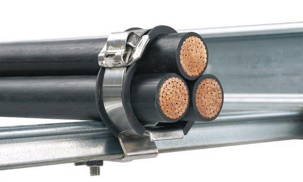
Figure 2 – A Highly Engineered Banding System – Note Integral Cushion Sleeve
What is a ‘Cable Cleat’?
Although the standard does require the manufacturer to describe a material type, it does not exclude any specific material, dictate any minimum dimensions or physical attributes. Annex A (informative) in the IEC cable cleat standard provides examples of various cable cleats which include products made from timber, steel and plastic.
There is a variety of designs and methods of ‘securing cables’, designs start at 15mm wide and go up to 150mm wide.
Defined by the IEC International standard, a cable cleat is simply: “A device designed to secure cables when installed at intervals along the length of the cables1”
1 International Electrotechnical Commission (2015). International Standard Ed. 2.0 2015-11.
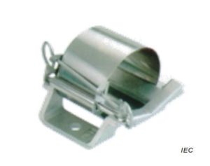
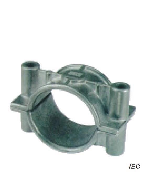
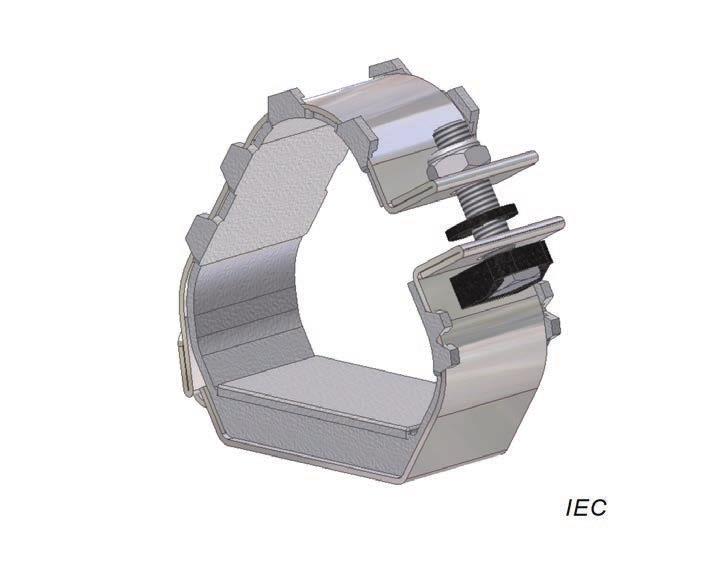
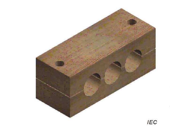
Examples of Cable Cleats
 |
 |
 |
 |
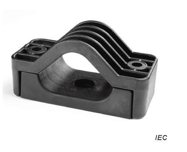 |
| Figure A.1 – Strap Cleat | Figure A.2 – Aluminium | Figure A.3 – Stainless Steel Cleat | Figure A.4 – Wood | Figure A.5 – Glass Filled Polymer |
Providing that the manufacturer tests and declares certain performance criteria, a ‘cable cleat’ can be any shape, size or material.
Hence, for example, a 19mm wide cable banding system can be used to secure cables in line with the IEC Cable Cleat standard providing it undergoes all the required tests and that they are carried out in accordance with the standard.
The term ‘cable tie’ is commonly used to describe a ‘strap cleat’ system which is not correct.
A light duty stainless steel tie or an injection molded ‘zip’ tie has many uses and play a vital role on many cable routing installations, but they must not be confused with a high-end strap cleat solution which can withstand immensely high electro-mechanical forces and are resistant to corrosion and ultra violet degradation.
What is the appropriate IEC International standard?
The IEC standard was originally a European standard, BSEN 50368:2003, which was improved and adopted over time by the International Electrotechnical Commission and the first version of IEC 61914 was published in 2009.The standard was further improved, and the current version of IEC 61914 released in 2015.
What specific tests does the IEC 61914:2015
Cable Cleat standard require?
The standard provides harmonised testing procedures for the following aspects:
- Temperature rating (-60˚C to +120˚C)
- Adequate resistance to flame propagation (very similar to UL 94)
- Lateral load testing (at maximum declared temp)
- Axial load testing (at maximum declared temp)
- Impact resistance (at lowest declared temp)
- Corrosion resistance
- UV resistance
- Resistance to electromechanical forces – the ability to withstand one short circuit event two short circuit events in succession
- 2015 Revision standardizes cable diameters for testing and permits clients to compare performance between manufacturers
2 International Electrotechnical Commission (2015). International Standard Ed. 2.0 2015-11.
What does the NEC code say about cable cleats?
In the United States the National Electric Code (NEC) Art 392.20 states “Single conductors shall be securely bound in circuit groups to prevent excessive movement due to fault-current magnetic forces3”.
While this section of the code dictates that the conductors must be bound securely to protect against fault-current magnetic forces, it does not specify how to secure the conductors nor recommend test methods to ensure products meet the force requirements.
Therefore, it is recommended that the IEC 61914:2015 standard is followed to comply with NEC Art 392.20.
Short circuit testing requirements of IEC 61914:20154 – an overview
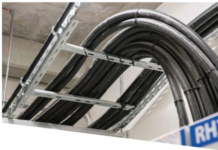
IEC 61914:2015 focuses on this most demanding aspect of testing compliance, short circuit testing, the manufacturer is required to test in accordance with section 9.5 of the standard which gives guidance for a suitable set up. The cables, which must be of a certain type and outside diameter, must be restrained at a minimum of five positions along the cable run.
The cables must be fastened to a surface defined by the manufacturer, and this is usually a standard cable ladder, with rungs every 300mm.
The cables are then subjected to a three-phase short circuit consisting of an initial peak current and then a decaying R.M.S. of a duration of not less than 0.1s.
The accredited test laboratory must include the following information in the published test report:
- The manufacturers catalogue references
- The assembly details showing:
- The number of restraints and their spacing
- The cable centre to centre spacing
- Cable conductor diameter, insulation thickness, external diameter and markings
- A pre-test photograph of the set-up and a post-test photograph commenting on the condition of the restraints
- The test duration
- The ambient temperature
- For cleats which are classified to 6.4.4 (one short circuit):
- There shall be no failure that will affect the intended function of the cable of holding the cables in place.
- All restraints shall be intact with no missing parts
- There shall be no cuts or damage visible to normal or corrected vision to the outer sheath of each cable, caused by the restraints
- And for cleats which are classified to 6.4.5 (two short circuits)
The restraints shall comply with all the requirements shown above for the first hit, but then in addition, after the second hit, a voltage withstand test is performed by applying a minimum test voltage of 2.8kV d.c. or 1kV a.c. for a period of 60 (+5/-0) seconds.
The test is administered between the cable cores, which should be connected together and the mounting frame. The cable jackets, restraints and mounting frame should be pre-wetted with sufficient water to facilitate a current leakage path along the outer jacket for 2(+1/-0) minutes before the test begins. The cables shall meet the requirements of the voltage withstand tes without failure of the insulation.
3National Electrical Code 2017 Edition (2017).
4International Electrotechnical Commission (2015). International Standard Ed. 2.0 2015-11.
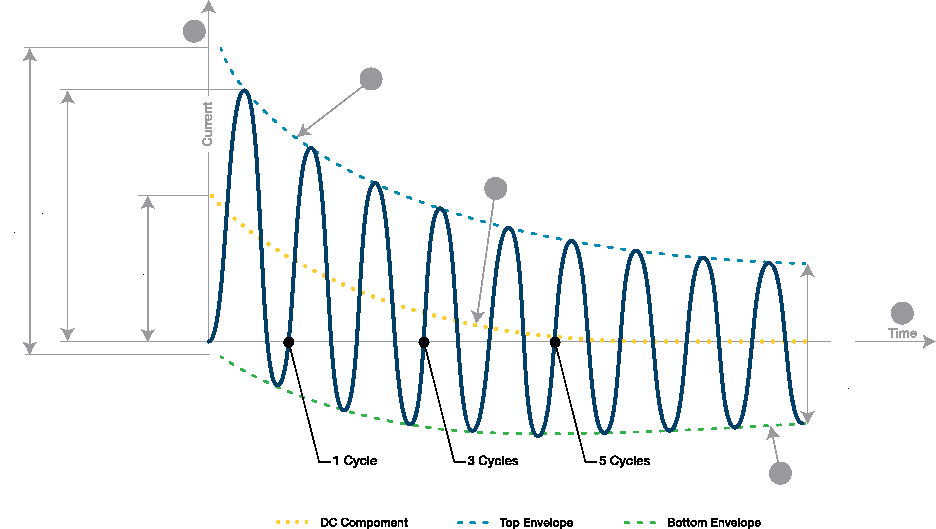
| Key | |
| 1 | Current |
| 2 | top envelope |
| 3 | decaying d.c. component, id.c. of the short-circuit current |
| 4 | bottom envelope |
| 5 | Time |
| A | initial value of the d.c.component, id.c. of the short-circuit current |
The electromagnetic forces during a fault can be enormous and occur instantaneously at the peak of the fault, i.e. the first quarter cycle (5ms on a 50Hz system and 4ms on a 60Hz system).
Considering the pass criteria described above it is not easy to obtain a successful result.
However, further to extensive research and development Panduit now have scores of successful short circuit rated banding systems. Depending upon the project requirements, Panduit has a fully tested, full approved banding solution to accurately match the specific needs of the project.
Panduit Cleat kAlculator | App Store
‘Debunking the myths’
Misconception #1 – a cable banding system cannot restrain the forces during a fault
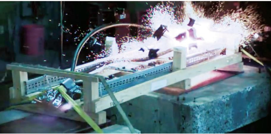
Recent articles in the industry press suggest that a cable banding system is not capable of withstanding the electromechanical forces and a series of video clips show an incorrectly specified cable tie installation failing during fault. The issue here is that the tested product was not suitable for the intended installation.
It might well have been the case that this weaker tie was specified by the system designer, and here lies the true problem, an incorrect specification. The product used in the test was never designed to withstand these forces; a correctly specified and engineered banding system certainly would.
Cable Strap Banding System
To suggest that a strap banding system is not suitable for short circuit rated installations is incorrect and is out dated information. The cable system designer must make sure that the fault levels have been accurately calculated and then specify a fixing system which meets that requirement and complies fully to IEC 61914:2015.
Misconception #2 – a banding system has sharp edges and will cut the installer during installation / damage the cable during fault conditions
As described previously, to achieve a successful short circuit test is difficult. After both the first and second short circuits each cable at every restraint position is inspected by test laboratory personnel; there can be no cuts or damage to the outer jacket.
Furthermore, after the second short circuit the laboratory carry out the voltage withstand test to check for current leakage and any hidden damage which may have occurred underneath the band itself.
Panduit’s extensive range of cable strapping and banding products have full certification to both classifications of short circuit test. The use of a protective sleeve moulding, common on many cleat types, and the use of rolled edge banding material ensures the cable is protected regardless of fault level.
To suggest that this type of product is not suitable for short circuit rated installations because it will damage or cut the cable or cause cuts and injury to personnel is incorrect and out dated information.
Other advantages of Panduit’s Banding Systems
- When compared to a ‘traditional’ design of cable cleat the banding system has a much larger range taking ability. This is a huge advantage from a purchasing and stock keeping perspective; quite often one part number from a Banding System covers the same range take as perhaps four or five ‘traditional’ cleat part numbers.
- A banding system takes up minimum space when installed around the cables. This is a very important factor when space is limited e.g. across the width of a ladder rung or when available height is limited e.g. between layers of ladder runs.
- A fault rated band will be typically less expensive to buy and quicker to install.
- A large quantity of banding system products takes up much less physical space on site before installation compared to ‘traditional’ cleat systems. This also leads to less packaging, less waste and generally a lower carbon footprint.
- Panduit’s global network of distributors ensures local product inventory, product support, and a wide range of logistical services no matter where a project is. As an added level of support, Panduit also offers an optional engineering review, including physical documentation such as test reports, product brochure, drawings, and data sheets.
- The Panduit strap cleat system is considerably lighter than the traditional cleat alternatives offering huge advantages for transportation and moving around site.
- The Panduit strap cleat system can be used on a variety of cable configurations and layouts, including single (multi-core) cables, trefoil, quadrafoil, and a whole variety of special cable layouts and arrangements.
- Panduit has more than 60 years of experience working with electrical design engineers, electrical contractors, and safety engineers and continuously reinvests in R&D. To date, Panduit has secured more than 2,000 patents, including several for cable cleats alone. With operations in 35 countries and customers in 120, Panduit distributes products, provides design expertise, and supplies technical support to customers on an international scale. Panduit is committed to helping organizations become more productive and profitable, and is always striving to put its partners ahead of their competition.
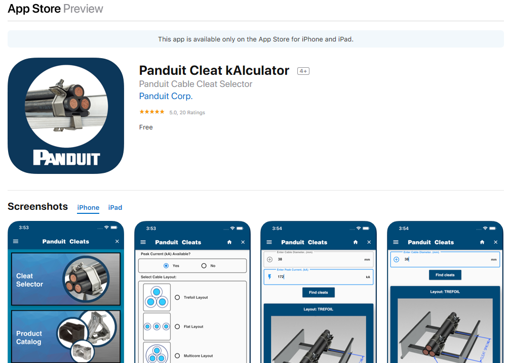
- Choosing the correct cable cleat to protect you unique project will assure optimal performance, reliability, and qualiity. Panduit is proud to introduce the new Cleat kAlculatorTM App for IOS and Android
To simplify this selection decision, three easy steps allow users to:
- Select a cable layout
- Input cable out diameter
- Input peak short circuit current
Panduit at the Forefront of IEC 61914
The below video explains how a short circuit event should be avoided at all costs.
However if they do occur regardless of how much prevention. When it does occur we need to ensure that the cables, infrastructure and facility are safe as well as the personnel by installing a proper cable cleat.
IEC 61914 2015 standard applies to cable cleats used in a cable tray to secure power cables. Standard outlines and structures how to properly test, design and install a cable cleat to prevent a short circuit.
Panduit has a vast range of cable cleat solutions allowing cables to stay covered if a short circuit fault occurs. This reduces the impact of disruption and damage to people and buildings.
Designed to make installation simpler when working in arduous environments in a many different applications, Panduit can find a product solution to meet your requirements as well as offering job productivity, reliability and safety.
Why Panduit Cable Cleats?
The industry’s first solution that has streamlined the selection process, tested to IEC standards bringing the vision of creating an engineering specifiable products to the EPC and Contractor firms.
| Tested to IEC 61914:2015, the latest and most globally recognised cable cleat testing standard |  |
| Simple and intuitive design leads to increased productivity |  |
| Industry-unique mounting brackets and installation tools |  |
| Compatible with a variety of ladder racks and cables |  |
THORNE & DERRICK
Thorne & Derrick are national distributors of LV, MV & HV Cable Installation, Jointing, Substation & Electrical Equipment – servicing businesses involved in cabling, jointing, substation, earthing, overhead line and electrical construction at LV, 11kV, 33kV, 66kV and EHV. Supplying a complete range of power cable accessories to support the installation and maintenance of low/medium and high voltage voltage power systems:
- Slip-on Cable Terminations
- Cold-shrink Cable Terminations
- Heat-shrink Cable Terminations
- Cable Joints – Heat & Cold-shrink
- Separable Connectors (Euromold)
- Surge Arresters & Switchgear/Transformer Bushings
Key Product Categories: Duct Seals | Cable Cleats | Cable Glands | Electrical Safety | Arc Flash Protection | Cable Jointing Tools | Cable Pulling | Earthing | Feeder Pillars | Cable Joints LV | Joints & Terminations MV HV
Cable Cleats from Ellis Patents | Better By Design
November 11th, 2019
-
uploaded by -
Chris Dodds - Thorne & Derrick Sales Marketing Manager
Major projects, new trains, bewildering technology: these are the big-ticket items that command everyone’s attention these days. And why wouldn’t they?
Who cares about the high-volume, low-cost bits and pieces that literally hold the railway together? Nuts, bolts, pins, clips, arms, brackets…
Politicians don’t cut ribbons at the installation of a cable cleat, but they might – conceivably – have to explain the havoc wreaked by one failing following an electrical big bang.
A single dodgy component can inflict disruption and embarrassment that’s wholly disproportionate to its size and cost, by a very significant factor.
With this in mind – as the magazine’s unofficial Analogue Correspondent (my heart was hewn from the earth by Victorian navvies) – I was despatched to Rillington in North Yorkshire to visit a company that’s been keeping cables in check for almost 60 years.
In parts, the experience proved surprisingly digital.
Basic Principles Of Cleating Cables
In case you’re unfamiliar with the term, a ‘cleat’ is used to secure LV MV HV electrical cables to a structure by installing them at intervals along the cables’ length. What could be simpler?
But there are a number of factors affecting its ability to fulfil that role safely and effectively, including environmental conditions, the materials used, performance in the case of fire or impact, resistance to corrosion and the cleat’s strength.

Installing Ellis brackets in the Severn Tunnel
The latter is often determined using a mechanical tensile test; however, the results can prove misleading as the force is applied in a slow, controlled manner.
The electromagnetic forces in short-circuit conditions act almost instantaneously and oscillate in every direction, sometimes with destructive consequences.
A cable cleat is most likely to fail at peak current, about 0.01 seconds after the event starts; a breaker won’t have woken up by then.
So, the only reliable way of demonstrating that a cleat will withstand the resulting forces is to also conduct a short-circuit test – International Standard IEC 61914 provides a formula for calculating those forces between two conductors in a three-phase supply. Potentially, they can amount to several tonnes.
Restraining cables during a fault is a fundamental role of the cable cleat; it’s a means of protection as well as support. In order to withstand the applied forces, the optimum spacing between each cleat can be determined using a formula which takes account of the required loop strength and peak short-circuit current.

Production of Centaur Cleats
Potted History Of Cable Cleats
None of this is news to the specialist team at Ellis – formerly Ellis Patents – which boasts a skilled workforce of around 60, mostly residing in the towns and villages around Rillington.
The firm was founded by Arthur Ellis, who piloted more than 90 bombing missions for the RAF during the Second World War.
Back on civvy street, he trained as a plumber and set about manufacturing plastic pipe clips and cable clamps, with electricity boards as his major customers.
That was 1962; today the firm has an annual turnover of around £7 million.
The operation moved to its current site in 1974, about a mile from the York-Scarborough line. Unfortunately, the village station had closed 44 years earlier. Following Arthur’s retirement in 1987, the company was acquired by Chris Calvert – its current chairman – and fellow investors from Walkern Victoria Industries. It acquired EDL Cable Supports in 2002 and has since become a global force, offering one of the most comprehensive catalogues of cleats, clamps, hangers and associated peripherals to international clients and projects.
As you walk around, you get the sense of an open, collaborative culture and an engaged workforce. Innovation is encouraged and facilitated through ongoing – and sometimes speculative – investment in new kit. This is not a company that’s resting on its laurels, but neither are staff being driven to distraction. Managing Director Richard Shaw tells me they are encouraged to go home at the appointed time and not check their emails. One culprit habitually ignores the edict whilst another recycles redundant equipment to assist with his construction of a traction engine! This seems a happy place.
Vertical Integration

Production tooling manufactured by Ellis
Unlike many competitors, Ellis is fully resourced in-house – not only designing its own products, but also building CAD models and subjecting them to finite element analysis. “This tells us where a component will break and under what force”, says Richard. “Then we can 3D-print it.
“We know the printed model is about 40 per cent of the strength of the real thing due to the difference in plastics so – when we test it – if it comes out at 40 per cent of the figure we were expecting, we know we’re on the right track. We can do all that work without ever making anything, but it gives us the exact volume of materials needed, how long it will take to manufacture and the price.”
Beyond that, Ellis’ capabilities extend to prototyping and tooling for die-cast and injection moulding. This creates enormous flexibility and an inventive mindset: when a client comes with a problem, ways and means are readily available to develop custom-made solutions.
Through the 37 miles of tunnel on High Speed 1, there’s an Ellis cable cleat every 600mm. When the consulting engineer first approached the company during construction, he told them he needed 70,000 bespoke aluminium cleats in 12 weeks. They were designed, tested and delivered on time.
Ellis products are deeply embedded on the London Underground and Hong Kong Metro; they also formed part of the design for the recent installation of overhead line equipment through the Severn Tunnel. Thousands of its Centaur cleats can be found in the London Power Tunnels – extending for 20 miles under the capital – as part of the firm’s biggest ever order, worth £1.5 million. And the UK’s Astute-class nuclear-powered submarines also feature its cable clamp products.
Attention To Detail
As we know, though, the railway is different; visit most of our classic tunnels and you’re unlikely to see many cleats. Instead, the approach taken since the advent of power, telecoms and signalling was to place the associated cables on hangers, fixed to the sidewall. It’s quick and makes life easy. But even here, there’s scope for improvement.
Stephen Walton, Ellis’ Technical Director, revealed: “We’ve reworked the traditional pressed-steel hanger to be stronger and safer by adopting a curved profile; they use less material so the shipping costs are cheaper. We’ve also developed polymer cable hangers which are lighter-weight, offer more insulation resistance and will never corrode.

Emperor Cleats
“A lot of what we’re doing is about making the products easier to carry and improve speed of install, responding to the needs of the contractors we’re increasingly working with.”
When legacy hangers become life-expired, Ellis has a modular retrofit system which can be secured in place without disturbing the existing cable system. There’s a delightful simplicity and elegance about these products. I spent much of my chat time with Richard and Stephen fiddling with a stackable twist-to-fit no-bolts cleat, a unique device conceived in response to a Network Rail enquiry. The action had something very pleasing about it.
Inevitably, there is a procurement challenge here. Ellis’ polymeric products are more expensive than its metal variants, but being less heavy improves installation efficiency – a big issue for the rail industry given the scarcity of possession time – whilst their longevity means that whole-life costs are lower.
Cable cleats can be supplied pre-assembled with the requisite fixings – pushing up the initial purchase price but delivering benefits that reduce costs overall. Until we get our heads around these issues and learn to buy smarter, better products and lower expenditure will elude us.
All That Glitters…
2019 represents another busy year for Ellis as it continues to grow the business. It has much to offer the rail sector through a sharp focus on innovation, responsiveness and value. Of course, its competitors would say the same thing – they have similar brochures, product ranges and part numbers. “Their ‘innovation’ is copying us,” Richard reflects ruefully.
It’s indicative of the company’s position in this market that others closely follow Ellis’ lead. However, whilst imitation is often flattering, it rarely compares favourably with the original.
By Graeme Bickerdyke
Further Reading
- IEC 61914 – Cable Cleats & Short Circuit Protection Calculations
- Fire Resistance & Cable Cleats – Surviving Fire, Flame & Extreme Heat
- Triplex Cleats – Selection Guide for Cleating 11kV BS7870 Part 4.10 Cables
- Stainless Steel Cable Cleats – Preventing Galvanic Corrosion Of Cable Fixings
- Ellis Patents Cable Cleats & Cable Basket Tray for Securing High Fault Level Cables
- Stainless Steel Cable Cleats v Ties – The Myths Debunked By Ellis Patents
Thorne & Derrick
T&D are Specialist Distributors to UK Distribution Network Operators (DNO’s), NERS Registered Service Providers, ICP’s and HV Jointing Contractors of an extensive range of LV, MV & HV Jointing, Earthing, Substation & Electrical Eqpt – this includes 11kV/33kV/66kV joints, terminations and connectors for both DNO and private network applications.
Contact our UK Power Team for competitive quotations, fast delivery from stock and technical support or training on all LV-HV products.
Key Product Categories: Duct Seals | Cable Cleats | Cable Glands | Electrical Safety | Arc Flash Protection | Cable Jointing Tools | Cable Pulling | Earthing | Feeder Pillars | Cable Joints LV | Joints & Terminations MV HV
➡ Read: Thorne & Derrick Announce Distribution Agreement & Contract With Nexans


