

Blog
Cable Jointing – An Art or Science?
March 26th, 2021Both.
Whether lashing in a Straight 6 resin joint to power a domestic shower or jointing 110kV cables to energise Brisbane, the cable jointer must concentrate during all stages of cable stripping, measurement and joint installation.
Make an error with your measure, flirt with failure.
Of course cable failures keep cable jointers busy.
But self-inflicted cable failures caused by bad jointing and the “jointer” will soon be hanging up his crimper.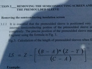
Quick joke. What’s the difference between a Jointer and a Doctor? A Doctor buries his mistakes – a jointer digs his up! Tumbleweed rolls through Blog.
Cable failures caused by poor jointing are costly.
Reputation damage plus consequential losses incurred by a power cut then multiplied by cost of the supply restoration as a formula is simply incalculable.
However, the ability to understand and apply complex mathematical formulae is a required staple of an EHV jointers skill-set.
Andrew Brezovsky is amongst many other things an EHV jointing legend and social media megastar. I suggest you Connect with Andrew on LinkedIn now – but don’t forget to hit the back button and rejoin us for a lesson in advanced cable jointing.
Cable Jointing Science
In todays lesson, Andrew considers the importance of the theoretical formula and the practical skill required in calculating and installing premoulded sleeves when jointing 110kV cable.
Removing the semi-conducting screen and installing the premoulded cable joint sleeve is a critical stage of jointing 110kV cables.
“So the calculation of the length of the premoulded sleeves when fitted is relying on the length of the mould, inner bore diameter of the tube, insulation diameter and the inner bore of the mould,” says Andrew.
Therefore, referring to the featured image above the calculation for the length of the premoulded sleeves is as follows:
- LS = length of cable joint mould when landed
- Z = overall length of mould as supplied
- A = inner bore diameter
- C = diameter of PVC tube
- Y = diameter of sleeve on PVC tube
- B = cable insulation diameter
Cable Jointing Art
“Here are a few shots from the mould loading process. The mould is being forced onto that PVC tube with the machine and silicone oil used as cable lubricant. The landing position is calculated individually for every cable joint to the point of a millimetre. You have to be good with your maths as the formula as you now know is complicated,” informs Andrew.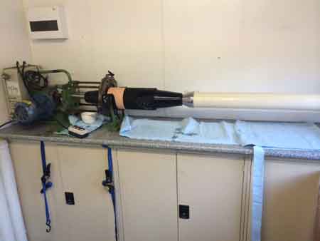
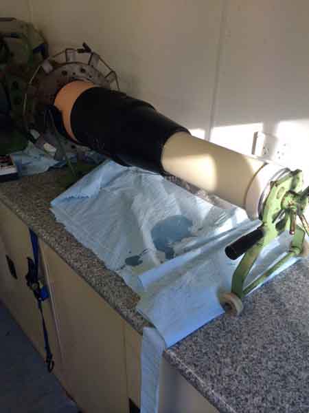
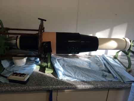 Images by EHV Cable Jointer : Andrew Brezovszky (EHV Cable Jointer – Energex Australia).

Jointers blog
Subscribe now to our POWER NEWSLETTER– a monthly email circulation packed with news, projects, videos, technical tips, training information, promotions, webinars, career opportunities and white papers.
Includes access to our popular JOINTERS BLOG with contributions from utility professionals, linesmen and cable jointers working on MV HV EHV cables and overhead lines typically at 11kV, 33kV, 66kV and up to 132kV.
15,000+ Subscribers. ➡ 
3M QS1000 Joint & 3M QTIII Termination – 11kV Triplex Cold Shrink Joints & Terminations
March 26th, 2021Images Courtesy of: Danny Williamson (LV HV Cable Jointer).
Danny is pictured below, jointing and terminating 11kV Triplex cables into medium voltage Schneider Ringmaster RN2c (RMU).
Schneider Ringmaster is a compact highly reliable solution for both indoor and outdoor MV distribution networks up to 13.8kV.
The 11kV joints and terminations were completed using Northern Power Grid (NPG) specification 3M QS1000 and 3M QTIII Cold Shrink kits – terminations include Sicame mechanical shearbolt cable lugs. 
Alroc cable strippers are pictured removing the red XLPE cable outer sheath which is the stage before the HV jointer must bend back the copper screen wires and remove the bonded semi-con layer.
Danny is also Pfisterer Connex size 1,2,3 3/S 3XL trained and authorised for live LV cable jointing on GTC networks and we look forward to featuring more examples of his work soon.
➡ Should you wish to feature and showcase your cable jointing skills on our Photoblog simply submit images with accompanying description to [email protected].

Good Housekeeping, Best Cable Jointing
“Some people tend to forget to treat all cables with same respect, whether they’re 11kV or 400kV. Any cable jointing area should be clean, neat and tidy – cable jointing tools handy and kept clean. Cables off the floor, away from dirt, dust etc. Danny Williamson has done that, he even has a tarpaulin over his head, sometimes you can only cook with what you’ve got, he has made an effort which is absolutely commendable,” commends Andrew Brezovszky.
3M QS1000 Cable Joint – 11kV. Cold Shrink tubes parked up the cable in the trench as the jointer uses connector holding tools to steady the mechanical connector as the shear-off bolts are installed. Copper wire screens secured with constant force springs are over-wrapped with 3M tape.
NPG specification Tapetile Cable Tile awaits roll-out to provide effective protection to the underground 11kV power cables.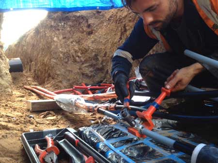
Jointing Tools. Perfect 11kV cable preparation using appropriate cable jointing tools.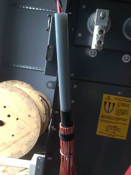 Cold Shrinking. The inner spiral from the 3M QTIII cable termination is unwound and the Cold Shrink tube with in-built stress control collapses onto the 11kV cable. Cold shrink jointing technology has virtually replaced heat-shrink material on UK DNO 11kV-33kV networks.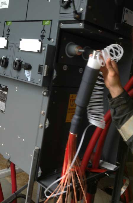
Connecting the 3M QTIII cable terminations onto the 11kV RMU bushings.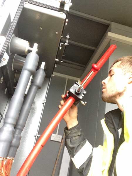
3M QTIII Cold Shrink Terminations Complete – 3M 92EE717 type universal bushing boots insulate the termination and protect against flashover. Copper wire screen entwined, identified with PVC insulation tape and bonded to earth stud. Heat shrink cable glands used to provide mechanical retention to the 11kV cables.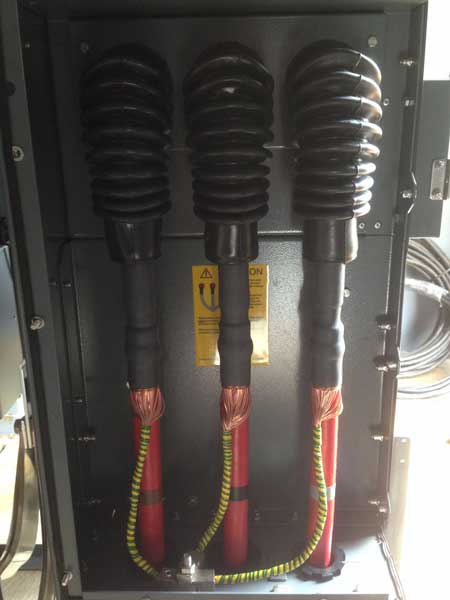
Jointers blog
Subscribe now to our POWER NEWSLETTER– a monthly email circulation packed with news, projects, videos, technical tips, training information, promotions, webinars, career opportunities and white papers.
Includes access to our popular JOINTERS BLOG with contributions from utility professionals, linesmen and cable jointers working on MV HV EHV cables and overhead lines typically at 11kV, 33kV, 66kV and up to 132kV.
15,000+ Subscribers. ➡
Extraordinary Fibre Earth Wire Pull
March 26th, 2021
Image courtesy of: Paul Everett MIET – Owner/Operator at UNS Limited.
Pictured: Extraordinary Fibre Earth Wire Pull
“Fibre earth wire pull completed today in Suffolk over 11 tower spans.”
Terminal tower in 132kV compound. Crossing over 2 x dual carriageways, 1 x 25kV electrified railway, 1 x 33kV overhead line, 3 x 11kV overhead lines, 1 x minor road.”
Included 1 x catenary system launch and 10 scaffold sides with 3 nets. “1 portable generation set connection, 1 x 11kV outage to create network mods and a further 11kV outage on day.” Paul Everett.
LOW, MEDIUM & HIGH VOLTAGE CABLES
LV MV HV PULLING & JOINTING EQUIPMENT
T&D supply UK and international contractors responsible for Low & High Voltage Power Cabling, Pulling, Jointing & Civil Engineering with cable duct, duct seals, lubricant, cable covers and tape tiles specified for 11kV/33kV installations.
PRODUCT OVERVIEW
| Cable Rollers | Cable Socks |
| Cable Drum Jacks | Cable Drum Trailers |
| Cable Winches | Conduit Rods |
| Cable Lubricants | Cable Blowing Equipment |
| Cable Protection – Tapetile 11kV | Stokbord 33kV | Cable Duct – Power, Fibre, Telecoms |
| Joints, Terminations & Connectors MV HV | Cable Duct Seals |
| Cables MV HV 11kV 33kV | Cable Jointing Tools |

Further Reading
11kV Cable Pulling – What Is The Maximum Distance For Ease of HV Cable Pulling Between Manholes
MULETAPE CALCULATOR | How To Select The Right Cable Pulling Tape For The Job
Cable Pulling For Alith Project 110kV XLPE Power Cable
Jointers blog
Subscribe now to our POWER NEWSLETTER– a monthly email circulation packed with news, projects, videos, technical tips, training information, promotions, webinars, career opportunities and white papers.
Includes access to our popular JOINTERS BLOG with contributions from utility professionals, linesmen and cable jointers working on MV HV EHV cables and overhead lines typically at 11kV, 33kV, 66kV and up to 132kV.
15,000+ Subscribers. ➡
Oil Leak Repair – Taking Leaks Seriously
March 24th, 2021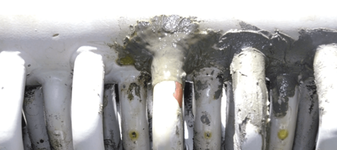
Oil Leak Repair

The following Technical Article about oil leak repair has been republished, with kind permission, from Transmission & Distribution World
Authors: Jon Allen and Anthony J. Picagli
Transmission & Distribution World’s mission is to provide utility executives, managers, engineers, supervisors, operators and linemen with must-read information on:
- Design
- Engineering
- Construction
- Operation
- Maintenance of the Electric Power-Delivery Systems
This includes an in-depth understanding of transmission, distribution, substations, automation and power flow control.
Oil Leak Repair
Taking Leaks Seriously
If oil is leaking out, air and moisture can and often do get inside transformers.
Moisture can migrate into transformers through several methods. One of the most common is through aged, leaking gaskets. Even though a transformer is at positive pressure, capillary action can draw moisture and air into a transformer, even when it is leaking oil.
Rapid pressure changes attributed to cold weather operation and sudden removal from service (a transformer switched out or de-energized) can increase the rate at which water is introduced into the transformer. Wherever oil is seen leaking from a transformer, the leaks should be repaired so moisture and oxygen cannot infiltrate the unit through those areas.
United Illuminating Addresses Oil Leak Repair with a Proactive & Ongoing Maintenance Program
The United Illuminating Co. (UI) regards the repair of oil and SF6 leaks as a critical component in its apparatus maintenance program. When a new leak is identified and immediate regasketing or replacement is not feasible, a temporary solution is scheduled to stop the leak. More than 10 years ago, UI began using outside specialists to seal oil leaks in its transformers and circuit breakers.
Previously, a special epoxy mixture was used to seal leaks at seams, pin holes, cracks and pipe connections. This option was easy to perform and inexpensive.
However, the results were inconsistent. With proper preparation, the epoxy repairs were effective about 50% of the time. In addition, removal of the epoxy for regasketing or replacement was extremely labour intensive. The utility’s fleet was aging, and UI engineers were interested in a better solution.
The utility had an initial experience with an outside contractor to repair a leaking circuit breaker that was going to be removed from service soon. As a test case, UI tested a leak repair technique as a temporary fix. The intent was to get by until the unit was changed out. The contractor used a flexible sealant material that had advantages over epoxy and was more effective in sealing the leak. The results were good, and UI has used the outside contractor approach elsewhere. The time and total cost savings were substantial.
Leaks Are Serious
Oil leaks need to be taken seriously and addressed with a proactive and ongoing maintenance program. The major issues addressed with leak repair are as follows:
- Environmental issues – Some of UI’s substations are located adjacent to the Long Island Sound, streams or wetlands; therefore, environmental impact absolutely must be avoided and clean-up costs kept to a minimum.
- Public perception – In reality, leaks may be contained and not be an environmental concern. But, if they are visible to the public, perception becomes an issue.
- Equipment outages – The extended outages required for conventional repairs are often difficult to obtain. Leak repairs can be done in areas with limited access and require shorter outage durations. In many instances, repairs can be made with the equipment energized.
- Resource availability – Resources are limited, whether people, time or money, and UI needs to maximize these resources. Additionally, staffing levels are influenced by the state of Connecticut’s Public Utilities Regulatory Authority.
- Replacement parts – As with any aging infrastructure, original equipment parts are often scarce, difficult to locate, expensive or simply no longer available.
- Delivery times – Along with the availability issue, parts that are available or need to be custom manufactured often have long lead times.
Cost Considerations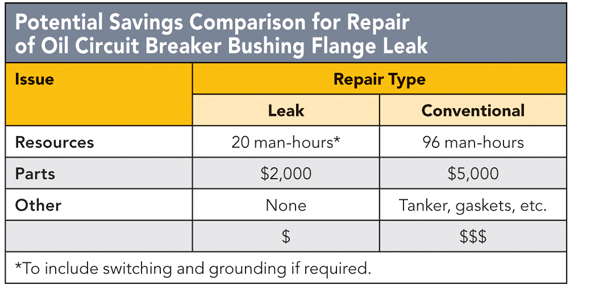
Oil leak sealing is not thought of as a permanent repair; it is a temporary patch until permanent repairs can be scheduled. Poor performers are known, whether by manufacturer, vintage or design, and are regularly inspected for problems. It really comes down to the financial analysis. In some cases, it can cost US$20,000 to filter the oil and another $20,000 to regasket properly. The leak repair alternative costs from $3,000 to $10,000. The interim fix must be considered.
Leak Seal Process
For more than seven years, UI has worked closely with The Colt Group in a proactive leak repair program. It began as an intensive series of repairs at multiple sites. It has matured into a more limited but ongoing inspection and maintenance routine. Some of The Colt Group’s repairs have become long-term solutions unintentionally, while other repairs were short-term fixes until UI could properly schedule and complete permanent repairs. Although the repairs are guaranteed for two years, many are still in place and working effectively several years later.
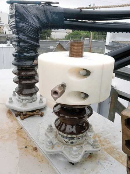
Sealant has been injected through an injection valve to fill a void inside this custom nylon enclosure installed on a UI bushing. The injection valves will be removed after the sealant cures and the enclosure will remain in place.
Over the years, UI has called on The Colt Group to make a variety of leak repairs to both transformers and circuit breakers. Two different methodologies are used, either a drill and tap using injection valves, or custom-fabricated clamps or enclosures. The drill-and-tap technique is used for oil leaks, while clamps or enclosures are used for certain oil leak applications, or for SF6 or nitrogen leaks.
The sealant used in these methods is not an epoxy. Flexible and easily removed, the sealant is specially formulated for use with high-voltage electrical apparatus. It maintains a memory that allows for expansion and contraction as needed, as a result of temperature changes and vibration. The substance has excellent dielectric properties as documented by test results from an independent laboratory.
Drill & Tap
In the drill-and-tap method, an experienced technician drills and taps a 1/16-inch (1.6-mm) blind hole in between the bolt holes to intersect the groove or gasket. (A blind hole does not completely penetrate, stopping short of the opposite side of the work space.) Next, an injector valve is installed into the tapped hole. This injector valve allows the technician to control any oil flow that may occur during the next step. Using a 1/8-inch (3.2-mm) drill bit, the technician will then drill a hole through the injector valve to penetrate the seal area.
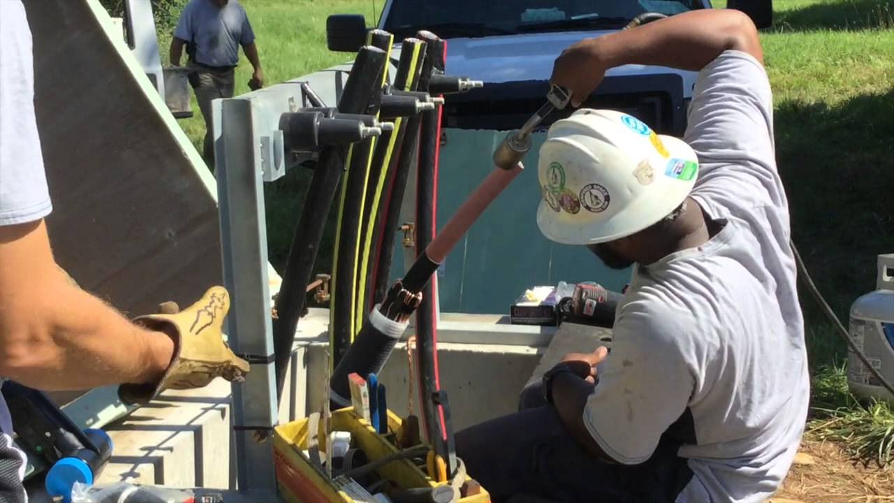
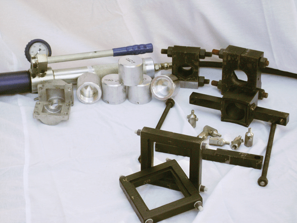 Specialty leak repair tool and equipment includes a manually controlled injection gun used for injecting sealant for both the drill-and tap method and installation of the custom clamps and enclosures.
The injector valve is then turned to the closed position. This process is repeated with additional injection sites and valves; the objective with the multiple ports is to carefully control the amount of sealant injected.
This is highly specialized work performed by technicians with years of experience. They have the expertise to know exactly where to drill, how deep to go and how much sealant to inject. Think of it as injecting a gasket from the outside in. With this non-invasive process, the oil does not need to be drained. Depending on the location of the leak, some of these repairs can be made with the unit energized. An example of a common in-service leak repair might be the bottom of a tap-changer flange or lower radiator flanges.
A two-part compound, the sealant has the consistency of peanut butter when first mixed. It is injected into the positioned valves one by one, using a manually controlled gun with pressure gauge. It takes approximately 1 hour for the sealant to cure. Once the sealant has cured, the injection valves are removed and Teflon-coated pipe plugs are inserted in the threaded holes.
On repairs that have a grooved or recessed area where the O-ring or gasket is located, that is a perfect spot to penetrate using the drill-and-tap technique. By intersecting this grooved area, there is a channel where the sealant can travel around and create a seal. This process can be used on tap-changer handles, tap-changer flanges, cover plates, belly bands, bushing mounting flanges and other locations.
Clamp Or Enclosure
The second leak repair methodology is a custom-fabricated clamp or enclosure. This creates a barrier around the leaking component by injecting the cavity of that piece of hardware to obtain a seal. This special hardware allows the sealant to be injected under pressure to successfully seal the leaks.
For enclosure repairs, two brief outages may be required. On the morning of day one, a 1-hour outage may be required for the leak seal technician to take precise measurements for the enclosure. The device can be fabricated that same day and delivered overnight. If required, a second outage of 4 hours to 6 hours is taken to install the enclosure. Sealant is injected into a channel inside the clamp to seal the leak. The clamp remains in place and can be removed easily when needed.
Many leak repair jobs are unique. In addition to the drill-and-tap method and the custom clamp or enclosure method, sometimes a weir can be fabricated and filled with sealant to seal leaks at the base of radiator fins or cooling rods. This somewhat decreases the cooling capacity but can be an effective short-term solution until a replacement is possible.
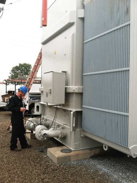
A leak repair technician injects sealant into a custom enclosure at UI. The injection valve will be removed after the sealant has cured.
Substantial Savings
This is a proven process. UI and The Colt Group work closely together to seal any new leaks that develop while monitoring past repairs. Some leak repairs considered temporary fixes years ago are still holding well. The overall situation is greatly improved and under tight control. UI estimates significant savings in annual maintenance costs by using leak repair as an integral part of its overall maintenance strategy and reducing the need for regasketing and replacement.
Companies mentioned
The Colt Group
Public Utilities Regulatory Authority
Risk Management Int’l
Thorne & Derrick stock and supply the DrainEezy range of transformer bund filters for use with LV MV HV Oil-Filled Transformers providing passive, self-regulating environmental protection and preventing bunds from overflowing during rainfall events; the DrainEezy Bund Filter System is field-ready to fit and retrofittable allowing clean water to drain freely while automatically blocking and retaining insulating oil in the event of a leak or catastrophic transformer failure.

600/1000V | 11kV | 33kV | 66kV Transformer Bund Filters
Further Reading
- 21st Century Costs of Underground Distribution
- Cable Replacement, Splicing & Terminating : A Video Tutorial
- Transformer Bunds & Oil Filled Substation Transformers – BS EN 61936-1 : 2010
- BundGuards | Substation & Transformer Oil Spills & Leaks Containment
THORNE & DERRICK
 Thorne & Derrick are national distributors of LV, MV & HV Cable Installation, Jointing, Substation & Electrical Equipment – servicing businesses involved in cabling, jointing, substation, earthing, overhead line and electrical construction at LV, 11kV, 33kV, 66kV and EHV. Supplying a complete range of power cable accessories to support the installation and maintenance of low/medium and high voltage power systems:
- Slip-on Cable Terminations
- Cold-shrink Cable Terminations
- Heat-shrink Cable Terminations
- Cable Joints – Heat & Cold-shrink
- Separable Connectors (Euromold)
- Surge Arresters & Switchgear/Transformer Bushings
Key Product Categories: Duct Seals | Cable Cleats | Cable Glands | Electrical Safety | Arc Flash Protection | Cable Jointing Tools | Cable Pulling | Earthing | Feeder Pillars | Cable Joints LV | Joints & Terminations MV HV
INVITE | ONLINE DEMO | Verisafe™ The Absence of Voltage Tester By Panduit
March 19th, 2021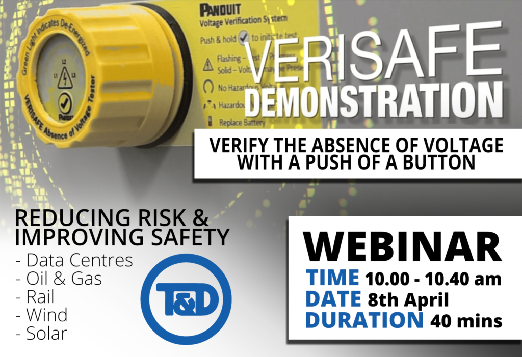
Verisafe
Absence of Voltage Tester
Are you ready to Lead the Way with Prevention through Design?
VeriSafe™ Online DEMO: Thursday 8th April 10.00 am – 10.40 am – REGISTER HERE
Thorne & Derrick International together with Panduit are pleased to Invite you to Register to a Joint Online Demonstration of the Verisafe ™
Due to high demand for a Demo of The Panduit Absence of Voltage Tester VeriSafe™ this innovative solution to prevent serious harm, we are running an online session.
In just over 30 minutes with an added Q&A section, walk away with an increased understanding of VeriSafe™ – the first-of-its-kind voltage tester that determines the absence of voltage with just a push of a button.
Learn how this SIL Level 3 compliant product automates the required six-step testing process in about ten seconds, enabling your plant to operate faster, safer, and more efficiently with:
- INCREASED PRODUCTIVITY
- IMPROVED SAFETY & RISK REDUCTION
- SIMPLIFIED PROCESS FOR EASIER COMPLIANCE
A simple button push enables electrical workers to verify the absence of voltage and see an active visual indication when the absence of voltage is confirmed.
This provides a new and innovative way to efficiently, reliably, and safely verify the absence of voltage before accessing potentially dangerous electrical equipment. Fail Safe. Meets SIL 3 IEC 61508-1.
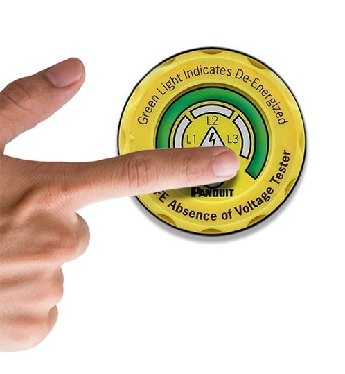
Safety is everything. Green means go. Verisafe™ provides reassurance that the area is de-energized
➡ VIDEO How To Verify Total Absence of Voltage By The Push Of a Button
REGISTER

Panduit and Thorne & Derrick ONLINE DEMO of Verisafe™

Glen Bate M.B.A.
Panduit Account Manager
Watch Glen Bate highlight how VeriSafe™, a product of Panduit’s Prevention through Design Safety Business, is focused on innovating groundbreaking new electrical safety technology that reduces risk, increases safety, and helps industry leaders achieve operational goals. Distributed in the UK by Thorne & Derrick.

Thorne & Derrick
T&D are Specialist Distributors to UK Distribution Network Operators (DNO’s), NERS Registered Service Providers, ICP’s and HV Jointing Contractors of an extensive range of LV, MV & HV Jointing, Earthing, Substation & Electrical Equipment – this includes 11kV/33kV/66kV joints, terminations and connectors for both DNO and private network applications.
Contact our UK Power Team for competitive quotations, fast delivery from stock and technical support or training on all LV-HV products.
Key Product Categories: Duct Seals | Cable Cleats | Cable Glands | Electrical Safety | Arc Flash Protection | Cable Jointing Tools | Cable Pulling | Earthing | Feeder Pillars | Cable Joints LV | Joints & Terminations MV HV
➡ Read: Isolate 99.999% Of Electrical Risks With Verisafe From Panduit
➡ Read: Verisafe AVT By Panduit | Safe & Sure Electrical Isolation


