

Blog
Underground Substation Cable Sealing | Protection of Metro & Rail Systems Against Moisture & Flood
November 26th, 2019
Underground Substation Cable Sealing
Underground Substation Cable Sealing
Product Category: Duct Seals
Application: Protection of Metro & Rail Systems Against Moisture & Flood
Sector: Rail
Product Installed: Filoseal+HD

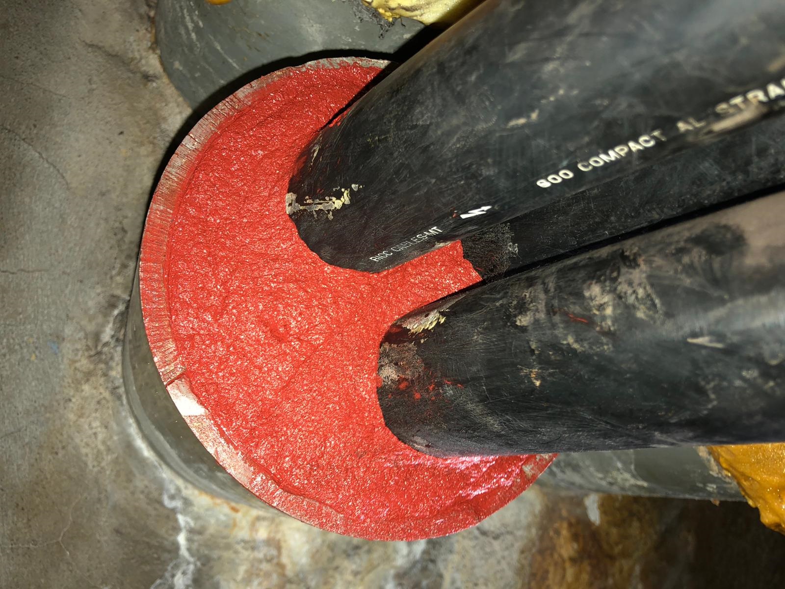
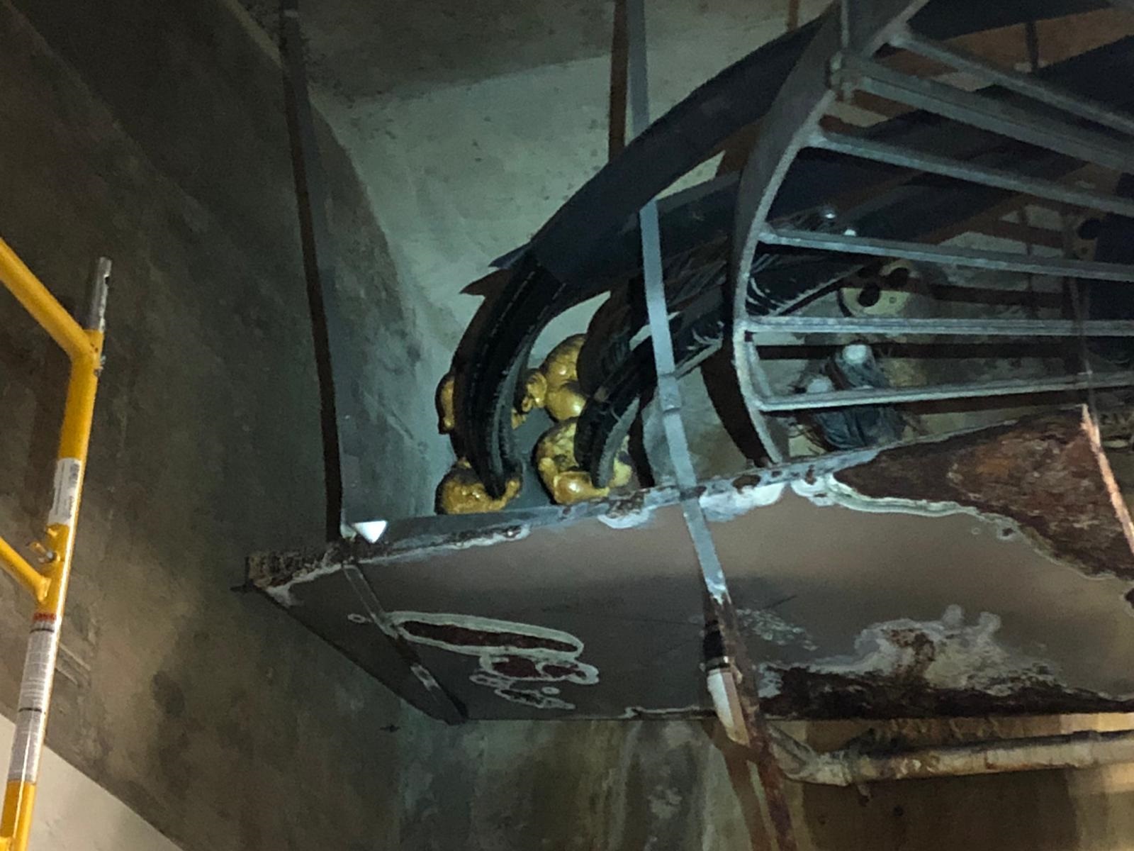
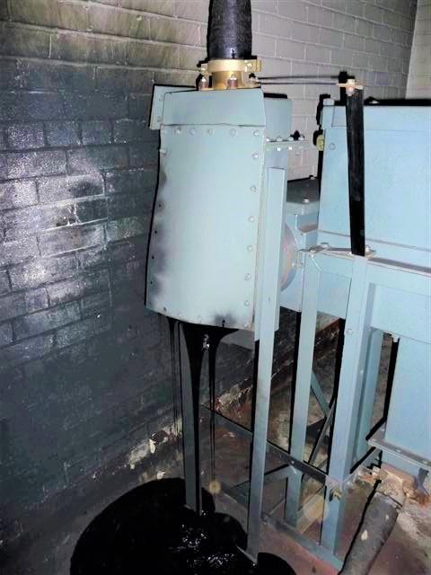
Here are several site installation photographs of a cable sealing and substation asset protection project in the USA.
The MV medium voltage cables are installed 20 meters underground in a substation that is providing electrical power distribution to a subway metro station.
This is one of many sites where they have ongoing moisture problems associated with floodwater and environmental conditions.
Using FiloSeal+HD the client improved the environment inside the substation, reducing moisture, which was their electrical and substation protection objective.
One of the main issues with this project was cable separation of the 35kV power cables which are installed in triplex formation.
FiloSeal+HD uses hexagonal-shaped tubes to support and separate the MV cables, which is one of the many reasons, this Utility decided to select and specify Filoform.
- Cable Sealing System – FiloSeal+HD + Water Blocking System
- Cables – 600MCM, 35kV TR-XLPE, Triplexed Cables
- Cable Duct Size – 160mm (6″)
As you can see, the visual element is far neater and professional, while also providing the following features:
- Up to 2 bar Pressure Resistance (Gas & Water)
- Flexible, one component, sealing compound – resistant to rats
- Resistant to Hydrogen Sulphide/Methane and aggressive gases
- Non-Hazardous – complies with 2011 NEC Articles 225.27, 230.8, 300.5(G), 300.7 (A) on Raceway Seals, and 501.15 (B)(2)
- Suitable for renovations – the cable duct seals can be installed retrospectively
DUCT SEALS


More Cable & Duct Sealing Applications
- LU London Underground Tested Cable Duct Seals – LUL S1085 Standard
- Correctly Sealed Cable Ducts Will Protect From Ingress Into Potable Drinking Water
- Sealing Cables, Switch Hall & Grid Transformer Bases On 132kV Wind Farm
- Duct Seals – Sealing Cable Ducts Containing Low Voltage Control Cables
- Sealing Cable Ducts Containing Multiple Single Core Cables In A Data Centre
- Trefoil Cables – Sealing Ducts & Cleating Trefoil Cables Up To 33kV
THORNE & DERRICK INTERNATIONAL
Since 1985 Thorne & Derrick based in the UK have been specialist distributors of LV, MV & HV Cable Installation, Jointing, Substation, Arc Flash Clothing & Electrical Safety Equipment – customers include UK and worldwide contractors, specifiers, traders and end-users involved in medium and high voltage cable installations, cable jointing, substation, overhead line and electrical construction.
We are specialist stockists and distributors of 11kV-33kV Cable Joints, Terminations & Connectors from manufacturers including 3M, Pfisterer, Prysmian and Nexans Euromold in a selection of cable jointing technologies including push-on, heat shrink and cold shrink joints and cold shrink terminations.
♦ 132kV Surge Arresters | 132kV Link Box Stockists

MV HV | Medium & High Voltage Power Products, Tools, Cables & Electrical Equipment
The Most Efficient & Simplest Cable Labelling System In the World
November 22nd, 2019
-
uploaded by Chris Dodds (Sales & Marketing Manager - Thorne & Derrick International)
Silver Fox Fox-In-A-Box®
Silver Fox are the leading UK manufacturer of cable labels and also the world’s most advanced labelling system for wires and cables, their Fox-In-A-Box.
Thorne & Derrick are Main Distributors for Silver Fox and can provide expert technical recommendations, installer training and competitive product supply from stock for cable labels to suit LV MV HV power, telecom, data, signal, network and fibre optic cables.
Labelling Features & Benefits
High specification and rigorously tested labels for cables with high resistance to salt mist spray, heat, flame, chemicals, gases (H2S) and UV for onshore and offshore environments – with fire safety testing and certification to BS 6853 for Toxic Fume and Smoke Density Emission to suit LSZH cable labelling applications.
Quality Tested
- LSZH Zero Halogen Smoke, Toxic Fumes & Oxygen Index Tested
- Network Rail Approved
- London Underground Approved
- Low Temperature -40°C 1000 Hours
- High Temperature 70°C 1000 Hours
- Chemical | Solvent Resistance Test
- H2S Sour Gas Exposure
- UV Weathering ISO4982 Part 3 Method A Cycle 1
| Productivity | 25,000 cable labels printed in 4 hours |
| Versatility | 11 types of cable labels with FIAB |
| Durability | 8000 hours accelerated UV age-tested permanent |
| Simplicity | Quick + easy to install – “turn time into profit” |

Image: ABB. Silver Fox cable labels are used throughout the utility and power generation markets to provide permanent and legible cable labelling of LV HV power, control and service cables in switchgear, control panels and substations.

Included in the Fox-in-a-Box® Basic kit:
- Labacus® Innovator Basic Label Software
- DTP-1/300 Thermal Printer- Plug’N’Play
- Thermal Printer Ribbon
- Printer Leads

This is ideal for users who just want to cut and paste information then print the cable labels. Should they want to do more then there is a seamless upgrade path from the Basic to the Advanced or Professional levels ready to go.
This means that the initial investment is not wasted, the upgrade price is the current incremental cost between the levels, plus a small administration fee.
To make it easier, all levels of software have internal videos. From these, the user can learn how to run the software in just 5 minutes by watching the video.
No internet access is needed!
All Silver Fox Thermal Labels are printed using One Software, One Printer and One Ribbon
3 Options
The Fox-In-A-Box® cable label system is available in three levels which offer increased software functionality for the DTP1/300 thermal printer – Basic, Advanced and Professional.
The Basic Fox-In-A-Box® allows users to create their own thermal cable labels, whilst the Advanced package adds the ability to accept or merge one or more columns in CSV files and to split the wire or cable label into more than one line.
It also allows the user to override the auto-font sizing and manually set this as required and to print from 2 rolls at the same time halving the label printing time and the print ribbon capacity.
The Professional model adds further functionality allowing the user to view and select individual or groups of cells for importing, duplicate cable ID’s, amend the number of labels required for each cable ID or produce cross ferruling ID and even print both ends of a wire at the same time.
Additionally, the Professional Fox-In-A-Box® can print bar codes and QR codes and import graphics for use such as printing warning signs on cable labels.
➡ Basic
Entry Level starter pack with Labacus® Innovator Basic software to print all of the thermal range of Silver Fox cable labels, the software also includes templates for all our laser range
- Cut and paste from spreadsheets straight into the software
 Automated USB port identification
- Seamlessly change between cable label types
➡ Advanced
Mid-range cable labelling pack includes Labacus® Innovator Advanced Software.
All functionality of the Basic plus:
- From CSV Spreadsheet – Import single columns/merge multiple columns
- Multiple line labels
- Choose your own font size
- Print 2 rolls of heat-shrink/non-shrink at same time
➡ Professional
Top end solution cable labelling system includes Labacus® Innovator Professional Software.
All functionality of the Advanced plus:
- Full spreadsheet view/import
 Select specific cells
- Produce cross ferrules
- Variable quantity duplication for each cable ID
- Bar Codes and QR Codes
- Import graphics and logos onto labels for asset management
| Order Code | Printer Model | Labacus Software |
| FIAB-BAS | DTP-1/300 | Basic |
| FIAB-ADV | DTP-1/300 | Advanced |
| FIAB-PRO | DTP-1/300 | Professional |
➡ Overview of Silver Fox Cable Labelling Products
- Tie-on LS0H Cable Labels
- Tie-on Cable Labels (PVC)
- Premium Heatshrink Cable Labels (Polyolefin)
- Tie-on Cable Labels (Durable Polyester)
- Low Smoke Zero Halogen Heatshrink Cable Labels (Polyolefin)
- Non-Shrink Cable Labels (PVC Tubing)
- 2 Part Cable Labels (Flexible Polyester)
- Wrap Around Cable Labels (Self Laminating Polyethylene)
T&D are proud to support UK manufacturing and develop new business opportunities in the power, rail, renewable, oil and gas and industrial market sectors.
“Everybody at Silver Fox are looking forward to working even closer with the Sales Team at Thorne and Derrick to build further on our already successful working partnership.”
“Since 1985 Thorne and Derrick have been a proactive, hard-working and well-respected distributor of LV MV HV Cable Installation, Jointing, Substation & Electrical Eqpt, who are committed to professional customer support. We are proud to include them as part of our distribution network,” comments Tammy Page, Marketing Manager (Silver Fox).
Silver Fox are leaders in UK manufacturing of cable labelling solutions, delivering innovative, durable and efficient systems for Data & Telecoms, Electrical, Transportation and Energy industries worldwide.
➡ Further Reading
- The Case for Low Smoke Zero Halogen Cable Labels & Public Safety
- How to Label Cables Safely In Zone 1 & Zone 2 Hazardous Areas
- Rail Cable Labels with Network Rail & London Underground (LUL) Approval
LV, MV & HV Jointing, Earthing, Substation & Electrical Eqpt
Thorne & Derrick International are specialist distributors of LV, MV & HV Cable Installation, Jointing, Duct Sealing, Substation & Electrical Equipment – servicing UK and global businesses involved in cable installations, cable jointing, substation, overhead line and electrical construction at LV, 11kV, 33kV and EHV.

Cable Cleats v Cable Strapping Bands | A White Paper by Panduit
November 21st, 2019
Panduit Cable Cleats For Short Circuit Protection
Cable Cleats v Cable Strapping Bands
-
A Whitepaper Republished Courtesy of Panduit -
by Chris Dodds | Sales Marketing Manager Thorne & Derrick
Cable Cleats v Cable Strapping Bands
Misconceptions
Recent articles in the industry suggest that a cable banding system is not capable of withstanding the electromechanical forces between the conductors in the event of a phase to phase fault. There is also a perception that a band type cleat product will cut the outer insulation of the cable under fault conditions.
This paper challenges these misconceptions and offers a more logical, engineered route to the correct specification of a cable fixing system. The reasoning is backed up and proven by independent third-party analysis and testing.
Traditional cable cleats started to appear in 1940’s and 1950’s predominantly in the U.K and Germany. These early cable fixing products were constructed from a variety of materials including timber, die cast aluminium and injection moulded polymers.
Due to the relatively weak or brittle mechanical properties of these materials the designs tended to be ‘over engineered’ to achieve the strength and performance required.
Figure 1
")
Figure 1. A Traditional Cable Cleat (Panduit 2-Hole Cable Cleat Used)
In more recent years, galvanised mild steel and 316 stainless steel options were developed which offered improved strength but still had a very bulky form factor. Early designs made in these materials offered a finished cable cleat which was twice the width and twice the height of the cable(s) being retained.
This was acceptable in single run applications e.g. when fastened sparingly to a wooden pole for utility applications, but when used in a cable ladder or tray application with multiple cable runs or within a substation where space and weight need to be carefully considered, the early designs did not meet requirements. Bulky cleat designs are not optimal.
However, recently introduced designs, materials and technologies have allowed Panduit to develop a high-end range of Strap Band products which meet or exceed the performance of a traditional cleat design when testing in accordance with IEC 61914:2015 by a third party lab. (Figure 2)

Figure 2 – A Highly Engineered Banding System – Note Integral Cushion Sleeve
What is a ‘Cable Cleat’?
Although the standard does require the manufacturer to describe a material type, it does not exclude any specific material, dictate any minimum dimensions or physical attributes. Annex A (informative) in the IEC cable cleat standard provides examples of various cable cleats which include products made from timber, steel and plastic.
There is a variety of designs and methods of ‘securing cables’, designs start at 15mm wide and go up to 150mm wide.
Defined by the IEC International standard, a cable cleat is simply: “A device designed to secure cables when installed at intervals along the length of the cables1”
1 International Electrotechnical Commission (2015). International Standard Ed. 2.0 2015-11.
Examples of Cable Cleats
 |
 |
 |
 |
 |
| Figure A.1 – Strap Cleat | Figure A.2 – Aluminium | Figure A.3 – Stainless Steel Cleat | Figure A.4 – Wood | Figure A.5 – Glass Filled Polymer |
Providing that the manufacturer tests and declares certain performance criteria, a ‘cable cleat’ can be any shape, size or material.
Hence, for example, a 19mm wide cable banding system can be used to secure cables in line with the IEC Cable Cleat standard providing it undergoes all the required tests and that they are carried out in accordance with the standard.
The term ‘cable tie’ is commonly used to describe a ‘strap cleat’ system which is not correct.
A light duty stainless steel tie or an injection molded ‘zip’ tie has many uses and play a vital role on many cable routing installations, but they must not be confused with a high-end strap cleat solution which can withstand immensely high electro-mechanical forces and are resistant to corrosion and ultra violet degradation.
What is the appropriate IEC International standard?
The IEC standard was originally a European standard, BSEN 50368:2003, which was improved and adopted over time by the International Electrotechnical Commission and the first version of IEC 61914 was published in 2009.The standard was further improved, and the current version of IEC 61914 released in 2015.
What specific tests does the IEC 61914:2015
Cable Cleat standard require?
The standard provides harmonised testing procedures for the following aspects:
- Temperature rating (-60˚C to +120˚C)
- Adequate resistance to flame propagation (very similar to UL 94)
- Lateral load testing (at maximum declared temp)
- Axial load testing (at maximum declared temp)
- Impact resistance (at lowest declared temp)
- Corrosion resistance
- UV resistance
- Resistance to electromechanical forces – the ability to withstand one short circuit event two short circuit events in succession
- 2015 Revision standardizes cable diameters for testing and permits clients to compare performance between manufacturers
2 International Electrotechnical Commission (2015). International Standard Ed. 2.0 2015-11.
What does the NEC code say about cable cleats?
In the United States the National Electric Code (NEC) Art 392.20 states “Single conductors shall be securely bound in circuit groups to prevent excessive movement due to fault-current magnetic forces3”.
While this section of the code dictates that the conductors must be bound securely to protect against fault-current magnetic forces, it does not specify how to secure the conductors nor recommend test methods to ensure products meet the force requirements.
Therefore, it is recommended that the IEC 61914:2015 standard is followed to comply with NEC Art 392.20.
Short circuit testing requirements of IEC 61914:20154 – an overview
IEC 61914:2015 focuses on this most demanding aspect of testing compliance, short circuit testing, the manufacturer is required to test in accordance with section 9.5 of the standard which gives guidance for a suitable set up. The cables, which must be of a certain type and outside diameter, must be restrained at a minimum of five positions along the cable run.
The cables must be fastened to a surface defined by the manufacturer, and this is usually a standard cable ladder, with rungs every 300mm.
The cables are then subjected to a three-phase short circuit consisting of an initial peak current and then a decaying R.M.S. of a duration of not less than 0.1s.

The accredited test laboratory must include the following information in the published test report:
- The manufacturers catalogue references
- The assembly details showing:
- The number of restraints and their spacing
- The cable centre to centre spacing
- Cable conductor diameter, insulation thickness, external diameter and markings
- A pre-test photograph of the set-up and a post-test photograph commenting on the condition of the restraints
- The test duration
- The ambient temperature
- For cleats which are classified to 6.4.4 (one short circuit):
- There shall be no failure that will affect the intended function of the cable of holding the cables in place.
- All restraints shall be intact with no missing parts
- There shall be no cuts or damage visible to normal or corrected vision to the outer sheath of each cable, caused by the restraints
- And for cleats which are classified to 6.4.5 (two short circuits)
The restraints shall comply with all the requirements shown above for the first hit, but then in addition, after the second hit, a voltage withstand test is performed by applying a minimum test voltage of 2.8kV d.c. or 1kV a.c. for a period of 60 (+5/-0) seconds.
The test is administered between the cable cores, which should be connected together and the mounting frame. The cable jackets, restraints and mounting frame should be pre-wetted with sufficient water to facilitate a current leakage path along the outer jacket for 2(+1/-0) minutes before the test begins. The cables shall meet the requirements of the voltage withstand tes without failure of the insulation.
3National Electrical Code 2017 Edition (2017).
4International Electrotechnical Commission (2015). International Standard Ed. 2.0 2015-11.

| Key | |
| 1 | Current |
| 2 | top envelope |
| 3 | decaying d.c. component, id.c. of the short-circuit current |
| 4 | bottom envelope |
| 5 | Time |
| A | initial value of the d.c.component, id.c. of the short-circuit current |
The electromagnetic forces during a fault can be enormous and occur instantaneously at the peak of the fault, i.e. the first quarter cycle (5ms on a 50Hz system and 4ms on a 60Hz system).
Considering the pass criteria described above it is not easy to obtain a successful result.
However, further to extensive research and development Panduit now have scores of successful short circuit rated banding systems. Depending upon the project requirements, Panduit has a fully tested, full approved banding solution to accurately match the specific needs of the project.
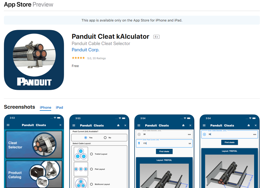
Panduit Cleat kAlculator | App Store
‘Debunking the myths’
Misconception #1 – a cable banding system cannot restrain the forces during a fault
Recent articles in the industry press suggest that a cable banding system is not capable of withstanding the electromechanical forces and a series of video clips show an incorrectly specified cable tie installation failing during fault. The issue here is that the tested product was not suitable for the intended installation.
It might well have been the case that this weaker tie was specified by the system designer, and here lies the true problem, an incorrect specification. The product used in the test was never designed to withstand these forces; a correctly specified and engineered banding system certainly would.

Cable Strap Banding System
To suggest that a strap banding system is not suitable for short circuit rated installations is incorrect and is out dated information. The cable system designer must make sure that the fault levels have been accurately calculated and then specify a fixing system which meets that requirement and complies fully to IEC 61914:2015.
Misconception #2 – a banding system has sharp edges and will cut the installer during installation / damage the cable during fault conditions
As described previously, to achieve a successful short circuit test is difficult. After both the first and second short circuits each cable at every restraint position is inspected by test laboratory personnel; there can be no cuts or damage to the outer jacket.
Furthermore, after the second short circuit the laboratory carry out the voltage withstand test to check for current leakage and any hidden damage which may have occurred underneath the band itself.
Panduit’s extensive range of cable strapping and banding products have full certification to both classifications of short circuit test. The use of a protective sleeve moulding, common on many cleat types, and the use of rolled edge banding material ensures the cable is protected regardless of fault level.
To suggest that this type of product is not suitable for short circuit rated installations because it will damage or cut the cable or cause cuts and injury to personnel is incorrect and out dated information.

Other advantages of Panduit’s Banding Systems
- When compared to a ‘traditional’ design of cable cleat the banding system has a much larger range taking ability. This is a huge advantage from a purchasing and stock keeping perspective; quite often one part number from a Banding System covers the same range take as perhaps four or five ‘traditional’ cleat part numbers.
- A banding system takes up minimum space when installed around the cables. This is a very important factor when space is limited e.g. across the width of a ladder rung or when available height is limited e.g. between layers of ladder runs.
- A fault rated band will be typically less expensive to buy and quicker to install.
- A large quantity of banding system products takes up much less physical space on site before installation compared to ‘traditional’ cleat systems. This also leads to less packaging, less waste and generally a lower carbon footprint.
- Panduit’s global network of distributors ensures local product inventory, product support, and a wide range of logistical services no matter where a project is. As an added level of support, Panduit also offers an optional engineering review, including physical documentation such as test reports, product brochure, drawings, and data sheets.
- The Panduit strap cleat system is considerably lighter than the traditional cleat alternatives offering huge advantages for transportation and moving around site.
- The Panduit strap cleat system can be used on a variety of cable configurations and layouts, including single (multi-core) cables, trefoil, quadrafoil, and a whole variety of special cable layouts and arrangements.
- Panduit has more than 60 years of experience working with electrical design engineers, electrical contractors, and safety engineers and continuously reinvests in R&D. To date, Panduit has secured more than 2,000 patents, including several for cable cleats alone. With operations in 35 countries and customers in 120, Panduit distributes products, provides design expertise, and supplies technical support to customers on an international scale. Panduit is committed to helping organizations become more productive and profitable, and is always striving to put its partners ahead of their competition.
- Choosing the correct cable cleat to protect you unique project will assure optimal performance, reliability, and qualiity. Panduit is proud to introduce the new Cleat kAlculatorTM App for IOS and Android

To simplify this selection decision, three easy steps allow users to:
- Select a cable layout
- Input cable out diameter
- Input peak short circuit current
Panduit at the Forefront of IEC 61914
The below video explains how a short circuit event should be avoided at all costs.
However if they do occur regardless of how much prevention. When it does occur we need to ensure that the cables, infrastructure and facility are safe as well as the personnel by installing a proper cable cleat.
IEC 61914 2015 standard applies to cable cleats used in a cable tray to secure power cables. Standard outlines and structures how to properly test, design and install a cable cleat to prevent a short circuit.
Panduit has a vast range of cable cleat solutions allowing cables to stay covered if a short circuit fault occurs. This reduces the impact of disruption and damage to people and buildings.
Designed to make installation simpler when working in arduous environments in a many different applications, Panduit can find a product solution to meet your requirements as well as offering job productivity, reliability and safety.
Why Panduit Cable Cleats?
The industry’s first solution that has streamlined the selection process, tested to IEC standards bringing the vision of creating an engineering specifiable products to the EPC and Contractor firms.
| Tested to IEC 61914:2015, the latest and most globally recognised cable cleat testing standard |  |
| Simple and intuitive design leads to increased productivity |  |
| Industry-unique mounting brackets and installation tools |  |
| Compatible with a variety of ladder racks and cables |  |
THORNE & DERRICK
Thorne & Derrick are national distributors of LV, MV & HV Cable Installation, Jointing, Substation & Electrical Equipment – servicing businesses involved in cabling, jointing, substation, earthing, overhead line and electrical construction at LV, 11kV, 33kV, 66kV and EHV. Supplying a complete range of power cable accessories to support the installation and maintenance of low/medium and high voltage voltage power systems:
- Slip-on Cable Terminations
- Cold-shrink Cable Terminations
- Heat-shrink Cable Terminations
- Cable Joints – Heat & Cold-shrink
- Separable Connectors (Euromold)
- Surge Arresters & Switchgear/Transformer Bushings
Key Product Categories: Duct Seals | Cable Cleats | Cable Glands | Electrical Safety | Arc Flash Protection | Cable Jointing Tools | Cable Pulling | Earthing | Feeder Pillars | Cable Joints LV | Joints & Terminations MV HV
What are the different types of Partial Discharge?
November 18th, 2019Republished from LinkedIn with kind permission of Neil Davies | EA Technology Australia | Helping Owners and Operators of Electrical Assets Improve Reliability and Efficiency
-
uploaded by Chris Dodds | Thorne & Derrick Sales Marketing Manager
Partial Discharge

Neil Davies
Partial Discharge (PD) can be classified into 3 main types:
Internal Partial Discharge, occurring inside insulation
Surface Partial Discharge, tracking across insulation
Corona Partial Discharge, from a sharp electrode into gas
Internal PD is the silent defect where there will be no sound, smell or visual indication of a problem prior to failure. If you witness the aftermath of a compound insulated cable box failure, you will see how the build-up of pressure can lead to a very disruptive and dangerous explosion.
Surface PD occurs across the surface of insulation. When alternative materials to porcelain started to be introduced into switchgear and dry cable terminations started being widely introduced, some critical aspects of design and installation were not fully appreciated. This led to a spike in failure rates due to surface PD. When developed, it will produce the crackling and ozone smell.
Corona PD is what we often hear in outdoor switchyards, particularly when humid. Corona at sharp points in switchyards isn’t usually detrimental. However, if corona activity occurs inside enclosed chambers and there is no airflow to remove chemical reactions, then it can lead to the onset of surface PD and problems.
EXPERT STRATEGIC AND TECHNICAL HELP FOR YOUR ELECTRICITY NETWORK
At EA Technology, we’re specialists in asset management solutions for owners and operators of electrical assets. We’re part of a global company, but bring local knowledge and advice in servicing the particular needs of the Australasian and Asia-Pacific market. This includes:
✔ Keeping ageing electricity networks operating reliability and safely.
✔ Adapting to major changes in network transformation, including smart grids, solar, wind and electric vehicles – while keeping costs down for customers.
✔ Predicting and preventing critical plant failures – literally keeping the lights on.
✔ Providing better visibility of the condition of electrical assets to allow for more informed planning and management.
✔ Investigating failure of electrical plants and assets to determine the cause and reduce future risk.
In Australia and the Asia-Pacific, we’ve been active for more than 20 years. Our teams have deep domain knowledge and provide unrivalled support to clients across Australia, New Zealand, China, and South-East Asia.
We are supported by a global team with headquarters in the UK. There, EA Technology was founded in 1966 and has a rich heritage as a ground-breaking research and development organisation serving the electricity industry.
LV, MV & HV Jointing, Earthing, Substation & Electrical Eqpt
Thorne & Derrick International are specialist distributors of LV, MV & HV Cable Installation, Jointing, Duct Sealing, Substation & Electrical Equipment – servicing UK and global businesses involved in cable installations, cable jointing, substation, overhead line and electrical construction at LV, 11kV, 33kV and EHV.
THORNE & DERRICK Product Categories: Duct Seals | Cable Cleats | Cable Glands | Electrical Safety | Arc Flash Protection | Cable Jointing Tools | Cable Pulling | Earthing | Feeder Pillars | Cable Joints LV | Joints & Terminations MV HV

Joints, Terminations & Connectors for MV HV Power Networks
The Distribution Network Operator (DNO) Transition to Distribution System Operator (DSO)
November 15th, 2019
Dr Vincent Thornley, Technology Director, Fundamentals Ltd
-
Republished with the kind permission of Fundamentals Ltd -
Uploaded by Chris Dodds (Sales | Marketing Manager at Thorne & Derrick)
Fundamentals Ltd recently held an industry event “Electricity Networks: Health, Performance and Transformation of the Grid”, and the transition to DSO featured in a number of presentations across the day, not just limited to the Transformation session.
A common theme for many of the speakers was clarity around a common objective, whether this related to DSO transition, solving customers’ problems, delivering services or building the 1000mph Bloodhound car.
Wrestling with Transformation
In essence, the GB electricity industry is undergoing an introspective period as it wrestles with its latest transformation project: Distribution System Operator (DSO).
Each of the current participants have their own view of what it is to be a DSO, which will naturally support their own business strengths. In the end it is Ofgem who may decide the scope through the licences it issues for the next regulatory period, ED2.
Customers of the electricity system and wider stakeholders are demanding greater flexibility, greater security, the ability to use more sustainable sources of electricity and to put it to wider use (e.g. transport), and all without huge increases in the cost of energy.
We need to keep in mind that a move to DSO should only be to support stakeholder needs such as these, rather than for its own sake.
Any attempt to define DSO results in extended discussion about what it is and everyone has a slightly different view.
The process should be to define the required roles (or functions) of the electricity system at distribution level, and for this a good starting point is a model already in use at transmission and market level: the ENTSO-E/EFET/eBIX Harmonised Electricity Market (HEM) Role Model.
A role-based model defines the functions required and the interaction between roles and domains of operation. Different actors can then take on combinations of these roles.

DNO vs. DSO | Image PPL
Working in Harmony?
The HEM role model is concerned primarily with the interactions between transmission systems, but the model and its definitions can be extended to the distribution layer.
The ENA Open Networks project seeks to define the functions of a DSO. However, rather than defining the entity of a DSO, taking a role-based approach including licensing could yield a number of key benefits:
- A more granular approach to licensing network and system services by the regulator. Ofgem could choose to licence different roles to different actors, and these may not be uniform throughout GB. It opens up the possibility of different operating models in rural settings to urban centres, which could include multi-utility system operation, or have a role provided by a city municipality.
- Alternative methods of delivery of some of the functions by different operators. An example of this is some of the ancillary service functions being delivered by Electricity North West’s CLASS project, within which Fundamentals is playing a significant role.
- Flexibility to adjust the licensing model as techniques develop. Indeed, within the bounds of operator suitability assessment, trading of licences could be allowed, reaching a more favourable operating point for the system. This will also enable new market entrants in the system.

CLASS | Electricity North West, a UK DNO, has started rolling out a revolutionary way of reducing demand for electricity across the North West, without anyone noticing a difference to their power supply.
Conclusion
Overall, the industry now requires a laser-like focus on the reason for the transformation: solving the energy trilemma.

Experts In hv Grid Control

Upgrading MV HV Transformers
With more than 20 years’ experience in grid control, Fundamentals are the only company to bring you an end-to-end engineering service that covers everything from consultancy, design and installation through to maintenance and ongoing support.
Fundamentals core expertise relates to voltage control for electrical power networks.
This comes from a deep understanding and practical experience of on-load tap changers, control schemes and the electrical network itself.
Building on this expertise, Fundamentals have developed a comprehensive range of services to fully support you on site for grid control.
- Total Tapchanger Solutions
- Protection and Control Schemes
- Transformer Upgrade Solutions
- HV Substation Services
- For more go to Company Voice
Pictured: Total Tapchanger Solutions – an innovative service from Fundamentals, with subsidiary Ferranti Tapchangers, provides an unrivalled one-stop-shop solution for all types of tapchangers and related control systems.

HV Services & Expertise
- Tapchangers – A Vital Component In Balancing The UK’s Power Supply
- Transient Fault Detection In Distribution Networks
- RIIO-2 A Fundamentally Frank Perspective
LV, MV & HV Jointing, Earthing, Substation & Electrical Eqpt
Thorne & Derrick International are specialist distributors of LV, MV & HV Cable Installation, Jointing, Duct Sealing, Substation & Electrical Equipment – servicing UK and global businesses involved in cable installations, cable jointing, substation, overhead line and electrical construction at LV, 11kV, 33kV and EHV.
THORNE & DERRICK Product Categories: Duct Seals | Cable Cleats | Cable Glands | Electrical Safety | Arc Flash Protection | Cable Jointing Tools | Cable Pulling | Earthing | Feeder Pillars | Cable Joints LV | Joints & Terminations MV HV
Joints, Terminations & Connectors for MV HV Power Networks
