

- Ensuring Optimum Performance Of Cembre Crimping Tool – Model HT131-C
- Cembre Cutting Tools Instructions For Use – Model B-TC950
- Cembre B1350-CE v. B135-C Crimping Tools Performance Comparison
- Replacing Cembre Cable Cutting Tool Blades – Model HT-TC051
- Maintenance For Cembre Cable Cutting Tool – Model HT-TC051
Blog
How To Purge Air Bubbles From Cembre Hydraulic Crimping Tool – Model HT51
June 12th, 2018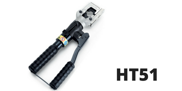
Cembre HT51 Hydraulic Crimping Tool
-
Uploaded by Chris Dodds - Thorne & Derrick Sales & Marketing Manager
Cembre HT51
Thorne & Derrick International are Main UK Stockists and Suppliers of Cembre tools including crimping and cutting types for all constructions of LV MV HV cable including medium/high voltage 11kV/33kV power cables.
The following short article provides useful instructions about how pure air bubbles correctly from the Cembre hydraulic circuit in relation to model HT51 cutting tool – built in safety valve also by-pass the oil supply when maximum pressure has been reached.
The following excerpts are taken from the Operating Manual of Cembre HT51 hydraulic crimping tool – however this information applies to the following tool model variants Cembre HT51-KV (insulated version).
Cembre HT51 crimping tool is lightweight and ideal for use in working confined switchgear and other LV-HV cable jointing, splicing and terminating applications.
The hydraulic crimping tool features spring loaded handles allowing the Cembre die sets to be advanced with one hand – the other hand is free to position the electrical connector or cable lugs prior to crimping.
For competitive prices, stock availability and technical advice about the Cembre HT51 tool please do not hesitate to contact us.
Purging Air Bubbles From Cembre HT51 Crimping Tools

HT51 Crimping Tool Position For Maintenance Operations
Air in the hydraulic circuit may affect the performance of the crimping tool. For example no lower die advancement, slow advancement of the lower die and lower die pulsating would all cause issues.
If this is the case proceed as follows:
4.1) To Purge Air Bubbles From Hydraulic Circuit
a – Hold tool upright in a vice with handles open (Fig 3).
b – Unscrew the main handle (04) from the body (13) to expose the rubber oil reservoir (03).
c – Remove reservoir cap (02).
d – Operate moveable handle (36) several times, in order to advance the tool ram (16).
e – Press the pressure release lever (44) to retract the ram (16), discharge oil pressure from the circuit and return all oil to the reservoir.
f – Repeat points (d – e) five times, to ensure all air bubbles in the hydraulic circuit are purged into the reservoir.
g – Remove all air from reservoir.
If the oil level is low top up as directed below.
h – Fit reservoir cap (02).
i – Assemble main handle (04) to tool body.
If the tool continues to malfunction return the tool for service.
Oil Top Up
Every six months check the oil level in the reservoir. If necessary, top up the oil level to the upper lip of the reservoir and remove all air from the reservoir (as described above).
Always use clean recommended oil – AGIP ARNICA 32 or SHELL TELLUSTX 32 or equivalent for HT51 and AGIP ITE360 or ESSOTRANSFORMER P60 or equivalent for HT51-KV
♦ Warning: Do not use old or recycled oil
♦ Warning: Do not use hydraulic brake fluid
HT51-KV tool contains oil with a high insulating power so it is imperative that you don not pollute it with other types of oil!

Cembre HT51 supplied with protective carrying case, tool manual and crimp die sets

LV Lugs & Connectors – complete range of copper crimp connectors suitable for use with joints and terminations for low voltage cables | Cable Lugs | Cable Splice Connectors | Aluminium Lugs | Aluminium Splices | Bi-Metallic Cable Lugs

Cutting & Crimping Tools
Cable Crimping & Cutting Tools
This post is from a series of articles written to provide advice and guidance on the care and servicing of Cembre cable cutting and crimping tools.

HV Lugs & Connectors – complete range of copper crimp connectors suitable for use with joints and terminations for medium/high voltage cables | Cable Lugs | Transformer Lugs | 2 Hole Lugs | Pin Stalk Connectors | Through Connectors | 11kV 33kV
Thorne & Derrick
Key Product Categories: Duct Seals | Cable Cleats | Cable Glands | Electrical Safety | Arc Flash Protection | Cable Jointing Tools | Cable Pulling | Earthing | Feeder Pillars | Cable Joints LV | Joints & Terminations MV HV | Cold Shrink
Cembre Cutting Tools Instructions For Use – Model B-TC950
June 12th, 2018
Cembre B-TC950 Cutting Tool
-
Uploaded by Chris Dodds - Thorne & Derrick Sales & Marketing Manager
Cembre B-TC950
Thorne & Derrick International are Main UK Stockists and Suppliers of Cembre tools including crimping and cutting types for all constructions of LV MV HV cable including medium/high voltage 11kV/33kV power cables.
The following short article provides useful instructions about how to correctly use the Cembre model B-TC950 cutting tool – prolonged use of the cordless hydraulic cutting tool can cause bluntening of the blades when cutting conductors, wires and cables.
The following excerpts from the Operating Manual of Cembre B-TC950 – however this information applies to the following tool model variants B-TC950A B-TC950E B-TC950T.
Cembre B-TC50 is a battery operated cable cutting tool suitable for diameters up to 95mm outside diameter and features their new Li-Ion 18V 4 Ah batteries providing improved cutting speed and cutting force with double-speed action for jointing and terminating copper or aluminium type cables.
For competitive prices, stock availability and technical advice about the Cembre B-TC950 tool please do not hesitate to contact us.
Instructions For Use – Model B-TC950
CEMBRE B-TC950

- Locking lever
- Upper cable cutting blade
- Lower cable cutting blade
- Handle grip
- Operating button
- Pressure release button
- Battery
- Battery capacity indicator
- Battery check button
- Battery release
- LED worklight
- Ring for shoulder strap
♦ Warning: Before starting any work, check the battery charge and recharge if necessary.
Follow the instructions in the battery charger user manual.
The tool can be easily carried using either the handle or the shoulder strap attached to rings (12).
To replace the battery, remove it by pressing the release button (10) then insert the new battery, sliding it into the guides until it locks.
Cutter Head Rotation
For ease of operation the tool head can rotate through 335° allowing the operator to work in the most comfortable position.
♦ Warning: Do not attempt to rotate the cutting head when the hydraulic circuit is pressurised.
Setting

Figure 3 & 3a Insert the conductor between the blades up to the cutting point
Insert the conductor between the blades, up to the desired cutting point (Fig. 3). For a running conductor, press the locking lever (1) and open the tool head (Fig 3a).
Fully retract the lower blade (3) before attempting to open the tool head. With the conductor on the lower blade (3), close the tool head and fully secure the lever (1).
♦ Warning: Before commencing the cutting operation ensure that the lever (1) is fully secured: partial closure may damage the tool head.
Cutting Blade Advancement
Press the operating button (5) (Ref. to Fig. 3) to activate the motor-pump. The ram will gradually move forward until the lower blade (3) touches the conductor.
To halt the advancement release the button (5) and the motor will cut out.
♦ Warning: Make sure the blade is exactly positioned on the desired cutting point otherwise re-open the blade following instructions and reposition it.
Cable Cutting
Firmly hold the tool and operate the button (5) to gradually move the lower blade (4) to cut through the conductor.
When the cut is performed release the button (5) to ensure the maximum pressure relief valve isn’t activated.
LED Worklights
Whilst the tool is in operation, the work area is illuminated by two high luminosity LED Worklights that switch off automatically at the end of the cycle.
Blade Retraction
By operating the pressure release button (6) the ram will retract and open the lower blade.
Battery Status

Figure 4 Battery Level Indicator
The battery is equipped with LED indicators that indicate the remaining battery life at any time by pressing the adjacent button (9):
- 4 LEDs illuminated: fully charged
- 2 LEDs illuminated: 50 % capacity
- 1 LED flashing: minimum charge, replace the battery
Worklights (11) illuminated combined with an alarm audible when the operating button (5) is pressed (Fig.4) is an indication that the battery voltage has dropped below a minimum safety threshold
Under these conditions the tool will not start and the battery should be replaced or recharged (80 minutes to fully recharge battery).
After each working cycle and the extraction of the battery from the tool, an integrated battery cut-off device will operate after approximately 70 s.
The LED nearest to button (9) will then flash 5 times each 14 s approx. The battery will be reactivated when it is reintroduced into the tool and the operating button is pressed.
Using The Battery Charger
Carefully follow the instructions in the battery charger user manual.
LV Lugs & Connectors – complete range of copper crimp connectors suitable for use with joints and terminations for low voltage cables | Cable Lugs | Cable Splice Connectors | Aluminium Lugs | Aluminium Splices | Bi-Metallic Cable Lugs
Cutting & Crimping Tools
HV Lugs & Connectors – complete range of copper crimp connectors suitable for use with joints and terminations for medium/high voltage cables | Cable Lugs | Transformer Lugs | 2 Hole Lugs | Pin Stalk Connectors | Through Connectors | 11kV 33kV
Thorne & Derrick
Key Product Categories: Duct Seals | Cable Cleats | Cable Glands | Electrical Safety | Arc Flash Protection | Cable Jointing Tools | Cable Pulling | Earthing | Feeder Pillars | Cable Joints LV | Joints & Terminations MV HV | Cold Shrink
Cold Shrink Joints | Jointing LV Cables Using 3M Cold Shrink Cable Joints
June 11th, 2018➡ Contact Thorne & Derrick International for the most competitive prices and largest UK stocks of Cold Shrink Cable Joints manufactured by 3M Electrical – specified extensively in the hazardous area industries including onshore and offshore oil, gas and petrochem for safe cable joints in potentially explosive atmospheres where “hot-working” is not permitted.
♦ See also the 3M Electrical range of Offshore Cable Joints suitable for power, control and instrumentation cables in the marine and offshore industries – includes NEK606 (RFOU BFOU EPR) and BS6883/BS7917 (UKOOA) offshore cables and specifications of cable joints compliant with the recommendations of the ATEX Directive for hazardous area cable installations distributing LV MV HV electricity supply.
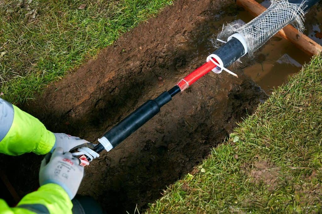
Cold Shrink Joints – LV HMV HV Power Cable Joints 600V/1000V 11kV 33kV
How To Apply 3M Cold Shrink Tubing – Underground Cable Joints
June 11th, 2018
A series of How-To videos for repairing, jointing and terminating cables using 3M Cold Shrink & Scotchcast products.
Cold Shrink
This video by 3M Electrical shows how to apply 3M Cold Shrink tubing safely for underground cable jointing processes and applications.
3M Cold Shrink tubing is a series of open-ended, tubular rubber sleeves, which are factory expanded and assembled onto a removable core – Cold Shrink tubes are supplied for field installation in a pre-stretched condition.
The 3M Electrical video shows how to install the cold shrink tubing and the full underground cable jointing process which is explained below:
- Position 3M Cold Shrink outer tube splice body and copper sleeve over the cable
- Install connector – a number of the 3M kits come complete with connectors
- Many connectors can be used providing they suit the requirements of the cable and fit within the Faraday cage
- Using 3M Cable Cleaning Wipes clean the cable and connector
- Once cleaned apply 3M P55 silicone grease leaving the connector until last to avoid contamination and smoothing out the grease to give an even coverage
- Move the splice body into place over the connector before unwinding the removable core to install the tube allowing the tube to shrink and form a waterproof seal
- Apply a layer of 3M Scotch Seal 5313 Tape to the end of the joint – a comfortable and durable mastic with excellent moisture and environmental seal
- Now tape over with the 3M Scotch 2228 Mastic Tape – a conformable self amalgamating temperature stable mastic
- Then reposition the copper sleeve over the joint fixing in place with 3M Constant Force Springs
- Now tape over with 3M Scotch 13 Semi Conducting Tape before applying more 3M Scotch 2228 Mastic Tape over the top
- Move the first 3M Cold Shrink Tube into place ensuring one end of the joint is completely covered
- Apply 3M Scotch 2228 Mastic Tape in preparation for the last protection tube
- Finally install the second 3M Cold Shrink Outer Protection Tube making sure to overlap the previous protection tube

Cold Shrink – invented by 3M over 40 years ago and now the preferred technology for heat-free jointing, terminating, sealing and abandonment of LV HV cables
We hope you find this video informative and educational, contact T&D for technical support, quotations and stock availability for 3M Cold Shrink Tubing.
➡ Visit 3M Electrical for further information about joints, terminations, tapes and insulation to seal, repair, splice and connect LV MV HV cables.

Cold Shrink | Joint | Terminate | Seal | Repair | Splice | LV MV HV Cables | 3M
- 3M Electrical Products Stocked By Thorne & Derrick International
How To Apply 3M Cold Shrink Cable End Caps
June 11th, 2018A series of How-To videos for repairing, jointing and terminating cables using 3M Cold Shrink & Scotchcast products.
Cold Shrink Cable End Caps
This video by 3M Electrical shows how to apply 3M Cold Shrink end caps safely.
3M Cold Shrink cable caps environmentally seal and mechanically protect exposed low, medium and high voltage cable ends using no tools, mastics or tapes.
The 3M video shows how cables ends can be quickly and simply sealed – simply position the end cap over the cable end and unwind the core to install the Cold Shrink cap onto the exposed cables.
Cold Shrink – invented by 3M over 40 years ago and now the preferred technology for heat-free jointing, terminating, sealing and abandonment of LV HV cables
We hope you find this video informative and educational, contact T&D for technical support, quotations and stock availability for 3M Cold Shrink Cable End Caps.
3M Cold Shrink Cable Caps Selection Chart
| 3M Cold Shrink Cable Caps Part Number | Cable Diameter Use Range (mm) |
| EC1 | 11.6 – 20.9 |
| EC2 | 15.9 – 30.1 |
| EC3 | 26.0 – 49.2 |
| EC4 | 45.5 – 84.3 |
| Test Methods | Typical Value |
| Colour | Black |
| 300% Modulus (ASTM D-412-75) | 480 psi |
| Ultimate Tensile (ASTM D-412-75) Original | 1400 psi |
| Ultimate Elongation (ASTM D-412-75) Original | 750% |
| Die C Tear (ASTM D-624C-73) Original | 150 pli |
| Fungus Resistance (ASTM G-21) 28 Days Exposure | No Growth |
| Moisture Absorption 7 Days at 90ºC in H2O | 1.8% Weight Gain |
➡ Visit 3M Electrical for further information about joints, terminations, tapes and insulation to seal, repair, splice and connect LV MV HV cables.
♦ Did you know? Cables can be insulated, protected and repaired using cold shrink tubing available in both EPDM rubber or fire resistant silicone.
Cold Shrink | Joint | Terminate | Seal | Repair | Splice | LV MV HV Cables | 3M
- 3M Electrical Products Stocked By Thorne & Derrick International


