

Blog
Cable Cleats – London Underground 1-085 Standard For Fire Safety Performance Of Materials
March 19th, 2018
-
Uploaded By Chris Dodds – Thorne & Derrick Sales & Marketing Manager
Cable Cleats
Thorne & Derrick a leading specialist distributor of cable cleats provide some information pertaining to the London Underground 1-085 Standard For Fire Safety Performance Of Materials – the purpose of the document download below is to define the requirements for the fire safety of materials, in terms of flammability, smoke emission and toxic fume emission, installed on the London Underground (LU) network.

Thorne & Derrick are Main Distributors for Ellis Patents – several ranges of Ellis Patents cable cleats are currently featured on the London Underground (LUL) Intranet system used by specifiers and buyers working on LUL projects.
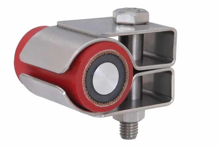
Non-metallic cable hangers are also available for the support, retention and suspension of rail cables within tunnels meeting the requirements of the 1-085 specification.
Independent testing confirms conformance to the 1-085 standard including toxicity, limited oxygen and smoke emission.
- Ellis Patents Alpha Cable Cleats – Aluminium Trefoil Cleats Product Register 360
- Ellis Patents Emperor Cable Cleats – Stainless Steel Single & Trefoil Cleats Product Register 362
- Ellis Patents Vulcan+ Cable Cleats – Stainless Steel Single & Trefoil Cleats Product Register 361
- Ellis Patents Phoenix Cable Cleats – Fire Rated & Resistant Cable Cleats Product Register 1661
- Ellis Patents Non-Metallic One Hole Cable Clamps – Product Register 363 364
- View the complete range of Ellis Cable Cleats

Cable Cleats | Ellis Patents Vulcan | Alpha | Phoenix | Flexi-Strap | Triplex Cable Cleats
London Underground 1-085
This standard specifies the requirements for materials installed in underground rail locations with regard to:
a) Flammability (including the risk of explosion)
b) Smoke emission
c) Toxic fume emission
➡ Should you require any assistance with the selection of cable cleats or cable accessories compliant with London Underground 1-085 Standard please do not hesitate to contact us.
Cable Cleats Blogs
- IEC 61914 – Cable Cleats & Short Circuit Protection Calculations
- Fire Resistance & Cable Cleats – Surviving Fire, Flame & Extreme Heat
- Stainless Steel Cable Cleats – Preventing Galvanic Corrosion Of Cable Fixings

LV, MV & HV Jointing, Earthing, Substation & Electrical Eqpt
Thorne & Derrick International are specialist distributors of LV, MV & HV Cable Installation, Jointing, Duct Sealing, Substation & Electrical Equipment – servicing UK and global businesses involved in cable installations, cable jointing, substation, overhead line and electrical construction at LV, 11kV, 33kV and EHV.
THORNE & DERRICK Product Categories: Duct Seals | Cable Cleats | Cable Glands | Electrical Safety | Arc Flash Protection | Cable Jointing Tools | Cable Pulling | Earthing | Feeder Pillars | Cable Joints LV | Joints & Terminations MV HV
Fire Resistance & Cable Cleats – Surviving Fire, Flame & Extreme Heat
March 16th, 2018
Cable Cleats – Undergoing Fire Resistant Testing
-
Uploaded By Chris Dodds – Thorne & Derrick Sales & Marketing Manager
Cable Cleats
There are currently no European or IEC standards for fire rated cable cleats or clamps, although there are requirements within other standards that can be followed to prevent unsuitable cable cleats being specified and installed.
The international standard IEC 61914 requires non-metallic and composite cleats to have adequate resistance to flame propagation only.
UL94, the standard for Safety of Flammability of Plastic Materials for Parts in Devices and Appliances, is a plastics flammability standard that classifies plastics according to how they burn in various orientations and thicknesses.
Adherence to its V-0 rating for polymer cable cleats should be demanded by specifiers.
For information UL94’s V-0 rating means that burning stops within 10 seconds on a vertical specimen; drips of particles allowed as long as they are not inflamed.
The use of the description LSF (Low Smoke & Fume) is common terminology with regard to polymers, but is misleading as it doesn’t relate to any published standard and so can be interpreted in a wide variety of ways.
To ensure complete assurance of performance in a fire, all Ellis Patents plastic cable cleat products have undergone testing at the Building Research Establishment (BRE) in line with the London Underground 1-085 Standard specification with regard to:
- Smoke emission
- Limited oxygen index
- Toxicity of fumes
The appropriate cleats are listed in the London Underground Approved Products Register.
Identification numbers are 360, 361,362, 363, 364, 365 and 1661.
A great deal of focus is placed on fire rated (FP) cables and their performance in fire, but very little attention is given to the cable fixings used to secure these cables.
Given that FP cable is typically rated for operation in temperatures ranging from 850°C to 950°C then the use of plastic cable cleats or clamps is clearly inappropriate.
Even aluminium only has a melting point of 660˚C, which means it would fail to support FP cables in a fire. To counteract this shortcoming, Ellis manufactures the Phoenix range of cable cleats for use with FP cables. Independently tested by Exova Warrington fire and BRE, all products in the Ellis Patents range are proven to perform to the same level as the FP cables ensuring continuous operation in the event of fire.
Ellis Patents Phoenix Cable Cleats – Fireproof & Fire Rated
Cable Cleats Blogs
- IEC 61914 – Cable Cleats & Short Circuit Protection Calculations
- Cable Cleats – London Underground 1-085 Standard For Fire Safety Performance
- Stainless Steel Cable Cleats – Preventing Galvanic Corrosion Of Cable Fixings
LV, MV & HV Jointing, Earthing, Substation & Electrical Eqpt
Thorne & Derrick International are specialist distributors of LV, MV & HV Cable Installation, Jointing, Duct Sealing, Substation & Electrical Equipment – servicing UK and global businesses involved in cable installations, cable jointing, substation, overhead line and electrical construction at LV, 11kV, 33kV and EHV.
THORNE & DERRICK Product Categories: Duct Seals | Cable Cleats | Cable Glands | Electrical Safety | Arc Flash Protection | Cable Jointing Tools | Cable Pulling | Earthing | Feeder Pillars | Cable Joints LV | Joints & Terminations MV HV
IEC 61914 – Cable Cleats & Short Circuit Protection Calculations
March 15th, 2018
IEC61914 – Calculating Short Circuit Forces To Specify Compliant Cable Cleats
-
Uploaded By Chris Dodds – Thorne & Derrick Sales & Marketing Manager
IEC 61914
Why Specify Cable Cleats?
“A cable cleat is a device designed to provide securing of cables when installed at intervals along the length of the cables”
taken from IEC 61914 Cable Cleats For Electrical Installations
Where the system peak fault current and the cable diameter are known, the formula above, excerpted from the international standard IEC 61914, can be used to calculate the forces between two conductors in the event of a 3 phase fault in order to specify the correct type of cable cleats.
Sub-standard or under-specified cable fixings including cable cleats and cable ties can cause catastrophic damage to infrastructure, power and life – for this no scientific formula exists to calculate the costs of power outage, plus the “nuisance factor”, downtime and consequential losses of reputation. Financially, that cost is immeasurable.
♦ Cable Ties
♦ Cable Cleats
Cable cleats are designed and specified to withstand those forces exerted by the cable in the “axial” direction in most types of cable installation, including Flexible Cable Systems and Rigid Cable Systems.
i) Flexible Cable Systems – where the LV-HV cables are “snaked” either vertically or horizontally, the cables can expand and contract freely between the fixing points.
ii) Rigid Cable Systems – where the LV-HV cables are rigidly fixed and longitudinal thermo-mechanical force is withstood by the combination of the stiffness of the cable, the cable cleat, reaction force and the rigidity of the support structure.
IEC 61914:2009 specifies requirements and tests for cable cleats and intermediate restraints used for securing cable in electrical installations.
Cable cleats provide resistance to electromechanical forces where declared – this standard includes cable cleats that rely on mounting surfaces specified by the manufacturer for axial and/or lateral retention of cables.
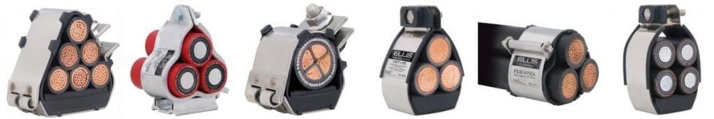
IEC61914 applies to the management and safe retention of all cable configurations and voltages (LV Low Voltage | MV Medium Voltage | HV High Voltage) including bundled, quadrafoil (quad cleats) or single cables installed in 3 phase formation using trefoil cable cleats.
Electrical design engineers and specifiers specify power cables from which the maximum anticipated short circuit load can be calculated.
This data enables the calculation of the force between the cable conductors in a short-circuit situation – cable cleats installed to cable containment (whether cable tray, ladder or basket) are in turn specified at the correct spacing to contain potential short-circuit forces generated by the low/high voltage power cable system.
The aspects of construction and performance covered by IEC 61914 include:
- Material type – i.e. metallic, non-metallic or composite
- Minimum and maximum declared service temperatures
- Resistance to impact at the minimum declared operating temperature
- The ability of the cleat to withstand axial slippage forces
- Resistance to electro-mechanical forces – i.e. the ability of the cleat to withstand the forces between the cables in the event of a short-circuit
- Resistance to UV and corrosion
- Flame propagation
The strength of a cable cleat is often determined using a mechanical tensile test.
However, the results may be misleading because the force is applied in a slow and controlled manner, which does not replicate fault conditions.
In a short-circuit fault the forces are applied almost instantaneously and oscillate in every direction. Experience shows that a cleat that survives a mechanical tensile test at a given force will not necessarily survive a short-circuit test, even if forces are the same.
IEC 61914:2009 also provides formulae to enable the theoretical forces between conductors in the event of a short circuit to be calculated.
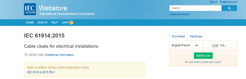
➡ Buy A Copy of IEC 61914 from the IEC Webstore.
Cleat Calculations
Where:
• Ft = maximum force on the cable conductor in Newton/metre (N/m)
• Ip² = peak short-circuit current in the kiloamp (kA)
• S = distance between the centrelines of the conductors in metres (m)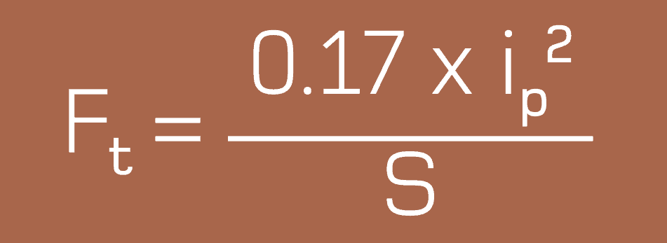
Once the Ft in N/m has been determined then the force for each potential cable cleat can be calculated.
For Example
Metric cable ladder typically has rungs at 300mm intervals, so cable cleat spacing is usually a multiple of this distance. So, Ft x 0.3 gives the force a cleat will see if spaced at 300mm, Ft x 0.6 for 600mm etc.
Ft x cable cleat spacing can then be compared to the maximum recommended mechanical loop strength of the cleat and then the cleat type and spacing can be selected.
Loop Strength of Cable Cleats
| Cable Type | Loop Strength (LS) |
| Alpha | 15,000N |
| Vulcan+, Protect and Standard Duty Flexi-strap | 36,000N |
| Emperor, Colossus and Heavy Duty Flexi-strap | 63,000N |
| Centaur Saddle and Clamps | 85,000N |
The formula uses peak current, however this is often unavailable with a Root Mean Square (RMS) value given instead – to calculate the peak current from the RMS, IEC 61914-1 Low Voltage switchgear and controlgear assemblies is commonly referred to, which uses the following multiples:
- 10 – 20kA = 2
21 – 50kA = 2.1
51kA = 2.2
Cable Cleat Calculations
Example 1
Peak fault: 110kA
Installation: Cable Ladder
Cables in trefoil with an outside diameter of 38mm.

| Ft2 x Cleat Spacing | Required Loop Strength |
| 0.3 for 300mm | 16,240 N per cleat |
| 0.6 for 600mm | 32,480 N per cleat |
| 0.9 for 900mm | 48,718 N per cleat |
| 1.2 for 1200mm | 64,958 N per cleat |
This force per distance can then be compared to different cleat loop strengths to ascertain the appropriate cleat and spacing requirements for specification. In this example, the Ellis
recommendation was for Vulcan+ cleats (LS: 36,000) spaced every 600mm, or Emperor cleats (LS: 63,000) every 900mm.
The overall length of the LV-HV cable run will determine the total number of cable cleats required – the spacing requirements for cleats is subject to cable formation, diameter and short circuit rating but quantity of cable cleats is a factor of the cable circuit length.
Example 2
RMS fault: 30kA
Installation: Cable Ladder.
Cables in trefoil with an outside diameter of 33mm

Cable cleated in trefoil formation using stainless steel cable cleats

| Ft2 x Cable Cleat Spacing | Required Loop Strength |
| 0.3 for 300mm | 6,134 N per cleat |
| 0.6 for 600mm | 12,268 N per cleat |
| 0.9 for 900mm | 18,401 N per cleat |
| 1.2 for 1200mm | 24,535 N per cleat |
As with Example 1, force per distance can be compared to the cable cleat loop strengths and the appropriate cleat and spacing specified.
In this example, Alpha cleats (LS: 15,000) spaced every 600mm are the best option.
Before a cleat and spacing are finalised, two other factors should be considered irrespective of the short-circuit level.
1) It is strongly recommended that a system employs a fault rated cleat or restraint at a maximum spacing of 1500mm.
2) On bends and risers it is recommended that the maximum cleat spacing is 300mm.

Ellis Patents – The Cable Cleat Specialists. Standard & Customised.
IEC 61914 has provided a standardised method for conducting a short-circuit test and a definition of the criteria for a pass. It does though allow for a significant degree of latitude and so caution must be employed when interpreting results. Note should also be taken of the full report as opposed to just its headline page.
Short-Circuit Testing
There is a major difference between the short-circuit withstand requirements of a cable and the short-circuit withstand of a cable cleat.
The former is concerned with cable degradation as a result of temperature rise (thermal stress heating), while the latter is concerned with cable retention as a result of electromechanical forces.
Typical installation specifications that have been derived from the thermal withstand of the cable would require a short-circuit withstand of 63kA for 1 second or 40kA for 3 seconds.
A short-circuit test for a cable cleat does not consider this heating effect, and instead concentrates entirely on the destructive electro-mechanical forces at peak, followed by a short term decaying RMS.
The international standard IEC 61914 requires a short-circuit test duration of just 0.1 second. This equates to five complete cycles, by which time the true strength of a cable cleat will be known.
IEC61914 notes “a cable cleat is provided with a means of attachment to a mounting surface but does not rely on an unspecified mounting surface for the retention of the cables. Examples of mounting surfaces that may be specified are ladder, tray, strut or rail, wire and beam. Where declared, cable cleats provide resistances to electromechanical forces.”
Ellis Patents Cable Cleats
All Ellis Patents cable cleats have been tested for both axial and lateral loads – this ensures the cleats will support the weight of all cable voltages including LV Low Voltage, MV Mediujm Voltage or HV High Voltage.
➡ See the complete range of Ellis Patents Cable Cleats

♦ Further Reading
CIGRE Technical Brochure TB194 – Mechanical Forces in Large Conductor XLPE Cables
CPD Course
Learn More About Cable Cleats
Ellis Patents the world’s leading cable cleat manufacturer has taken its UK accredited Continuing Professional Development (CPD) course – Cable cleats: a device for short circuit protection– online so that it can be used by engineering professionals, wherever they are in the world, as part of their on-going programme of career development and learning.
Mod 1. Introduction – includes a brief history of standards plus the importance of detailed specification to ensure the correct cable cleats and fixings are chosen for the environmental conditions and applications.
Mod 2. Electrical Theory – learn more about short circuit faults, why they occur and their impact on cable systems. Also, how to calculate the forces involved and therefore how to ensure the correct strength of cable cleats are specified.
Mod 3. Materials – different cable applications require different solutions. Learn how sunshine, pollution and marine environments can cause problems if the wrong cable cleat materials are specified. How to avoid bimetallic issues and how to prevent corrosion. The importance of fire safety and low emissions is also studied.
Mod 4. Testing Cleats – some exciting video clips of when things go wrong, and of good engineering practice. Appreciate the international standards that apply to cable cleat design and the rigorous procedures involved.
Mod.5 Cable Cleat Applications – an overview of some cable cleating applications and interesting special cable fixing projects.

LV, MV & HV Jointing, Earthing, Substation & Electrical Eqpt
Thorne & Derrick International are specialist distributors of LV, MV & HV Cable Installation, Jointing, Duct Sealing, Substation & Electrical Equipment – servicing UK and global businesses involved in cable installations, cable jointing, substation, overhead line and electrical construction at LV, 11kV, 33kV and EHV.
THORNE & DERRICK Product Categories: Duct Seals | Cable Cleats | Cable Glands | Electrical Safety | Arc Flash Protection | Cable Jointing Tools | Cable Pulling | Earthing | Feeder Pillars | Cable Joints LV | Joints & Terminations MV HV
Cast Iron Electricity Distribution Feeder Pillar By W Lucy & Co 1926
March 15th, 2018uploaded by: Chris Dodds - Thorne & Derrick Sales & Marketing Manager
The ornate cast iron electricity distribution feeder pillar was designed and manufactured by W Lucy & Co at The Eagle Ironworks and installed in Linton Road, Oxford in 1926.
The internal features of the distribution feeder pillar shows large porcelain fuses that protected the low voltage feeder cables – these would have been connected to the bottom of each of the 4 vertical 3-phase units.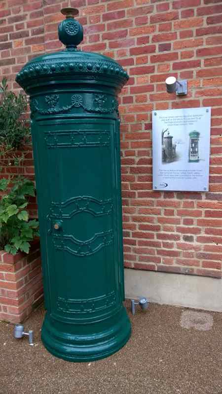
➡ For further information about how Lucy Zodion provide control and power distribution products for street lighting applications, please review the Lucy Titan (Cut-outs) and Lucy Trojan (Isolators) ranges of products.
Today, Lucy Zodion are established as the leading manufacturer of feeder pillars in cast iron, galvanised steel and stainless steel – retractable and pre-wired feeder pillars can be customised to customer specific requirements.
Their Fortress feeder pillars are the market leading range of LV Electrical Distribution Equipment available from stock for next day delivery.
The Lucy range of street lighting cut outs are approved by all UK Distribution Network Operators.


Manufacturers of Cut-outs | Street Lighting | House Service | DNO Utility
THORNE & DERRICK are national distributors LV, MV & HV Cable Installation, Jointing, Substation & Electrical Equipment – we service UK and global businesses involved in cable installations, cable jointing, substation, overhead line and electrical construction at LV, 11kV, 33kV and EHV.
Since 1985, T&D have established an international reputation based on SERVICE | INTEGRITY | TRUST.
Contact us for 3M Electrical, ABB, Alroc, AN Wallis, CATU Electrical, Cembre, Centriforce, CMP, CSD, Elastimold, Ellis Patents, Emtelle, Euromold, Filoform, Furse, Lucy Electric & Zodion, Nexans, Pfisterer, Polypipe, Prysmian, Roxtec, Sicame, WT Henley.

Invitation
Thorne & Derrick invite you to join LinkedIn’s largest LV-HV Electrical Discussion Group : Low & High Voltage Power, Cabling, Jointing & Electricals. Discussion subjects include cable installations, cable jointing, substation, overhead line and electrical construction at LV, 11kV, 33kV and EHV. Network, engage and promote your profile, company or products with over 10,000 influencers.


#ThrowBackThursday – HRH Prince Charles & High Voltage Cables
March 15th, 2018HRH Prince Charles & John Hayes from WPD (Western Power Distribution, UK Utility) discussing high voltage cable on the Isles of Scilly.
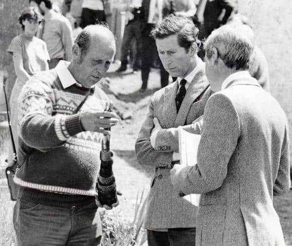
HRH Prince Charles & John Hayes from WPD
Further reading :
#ThrowBackThursday – A 150 Year History of the Tube
#ThrowBackThursday Film – The Pylon Men (1966)
#ThrowBackThursday Film – The Heart of the System
Thorne & Derrick
THORNE & DERRICK are national distributors LV, MV & HV Cable Installation, Jointing, Substation & Electrical Equipment – we service UK and global businesses involved in cable installations, cable jointing, substation, overhead line and electrical construction at LV, 11kV, 33kV and EHV.
Since 1985, T&D have established an international reputation based on SERVICE | INTEGRITY | TRUST.
Contact us for 3M Electrical, ABB, Alroc, AN Wallis, CATU Electrical, Cembre, Centriforce, CMP, CSD, Elastimold, Ellis Patents, Emtelle, Euromold, Filoform, Furse, Lucy Electric & Zodion, Nexans, Pfisterer, Polypipe, Prysmian, Roxtec, Sicame, WT Henley.
Invitation
Thorne & Derrick invite you to join LinkedIn’s largest LV-HV Electrical Discussion Group : Low & High Voltage Power, Cabling, Jointing & Electricals. Discussion subjects include cable installations, cable jointing, substation, overhead line and electrical construction at LV, 11kV, 33kV and EHV. Network, engage and promote your profile, company or products with over 10,000 influencers.
