

Cable Jointing Tools
Cable Spiking High Voltage Cables – UK Power Networks
November 14th, 2018
Cable Spiking High Voltage Cables – UK Power Networks
- Information Courtesy – UK Power Networks
8.13 Procedure for Spiking Cables
Following the identification of a cable, the cable will then need to be spiked using a cable spiker to ensure that it is not Live at HV. The following procedure shall be followed:
- If the process has not already necessitated a Sanction-for-Test, then a SFT must be obtained from Control (A SFT cannot be issued for idle or abandoned cables that are not part of a network, as Circuit Main Earths cannot be applied)
- If the cable has been identified by signal injection, it is not necessary to disconnect the instrument and re-apply the Earth
- The consent of the Control Engineer must be obtained prior to spiking
- Spike the cable
- Call Control and ask if any alarms have been received
- Before the spiking gun is removed, at least one of the verification tests, given below, must be conducted
- Following a positive result of the verification test, the earths will be re-applied and remain applied whilst the spiking gun is removed under the SFT and under the Personal Supervision of the recipient of the SFT. (this does not preclude the option of the SAP to issue a PTW to remove the spike gun)
- Furthermore, under the same SFT and following the removal of the spiking gun, the cable may be opened and stripped for phase colour tests to be made under the Personal Supervision of the recipient of the SFT (this does not preclude the option for the SAP to issue a PTW to open and strip the cable)
- SFT to be cancelled and a Permit-to-Work shall be issued for work to commence on the cable.
Injected Signal Strength Verification
Listen to the signal on either side of the spiking gun.
The signal strength on the side on which the signal is being injected should be distinctly louder than that on the furthest side. This is because the spike driven into the cable will be providing a short-circuit route for the signal. Therefore much less signal, if any, will flow to the end of the cable where the circuit main earth has been applied.
Verification by Insulation (Megger) Testing.
Prior to spiking, remove all the Earths and megger the cable. The cable can be tested between phases and between phase to Earth.
The tests should show healthy insulation values.
After spiking, test the cable again. The results should show a faulty cable, thus proving that the correct cable has been spiked.
Why Must Control be Contacted Before Spiking?
It is a requirement of DSR 5.9.2.
The consent of the Control Engineer must be obtained before spiking, to alert their attention that an incorrect spiking may have occurred, if an alarm is received.
The Control Engineer also has a final opportunity to prevent the spiking, if a feeder trips on the network in that vicinity. The circuit may be required to support the load and so the job may have to be postponed.
Why Must Control be Contacted After Spiking?
It is a requirement of DSR 5.9.2.
The Control Engineer must be contacted after spiking, so that a check may be made for any alarms that could be linked to the spiking. The Control Engineer may need to check with other Control Engineers. This is because there have been occasions when cables have been incorrectly spiked and the alarm has been received and accepted by another Control Engineer and not communicated to the Control Engineer dealing with the cable spiking.
8.14 Spiking Requirements of Circuits Comprising of Single Core Cables
In normal circumstances the spiking gun should be applied such that all three cores are spiked. However in the following circumstances it is essential that all three cores are spiked:
- 11kV Networks with Arc Suppression Coils
- 11kV Networks fed from Unganged Fuses
- Pot / Stop Ended Circuits
General
There may be occasions [excluding (i), (ii) or (iii) above] where it is only required to work on one or two of the single core cables. It would therefore be undesirable to spike and damage all three.
If only one or two of the single core cables are to be spiked, then insulation tests before and after spiking shall be conducted, to confirm that the correct circuit has been spiked. It will be necessary to use an instrument that applies a sufficiently high voltage, to detect the damaged caused by the spiking. This is necessary, as the single core cables may be completely severed by the spike and may appear as an open circuit (and therefore healthy), if the voltage applied by the instrument is too low.

PICOUP 400 Hydraulic Cable Spiking & Cutting Tool
Cable Spiking & Cutting Tools | Check Voltage Absence on LV MV HV Power Cables
Hydraulic & Remote | Suit SWA Cables up to 140mm Dia | More info PICOUP 400
8.15 Re-location of point of work
Following the positive identification and spiking of a cable, it may be necessary to change the point of work after issuing a Permit to Work e.g. when dampness testing. This may be done, without reference to the Permit issuer, and without the need for further spiking, provided that the Permit holder can physically trace the cable by means of a running noose from the initial point of work, to the new point of work.
➡ Thorne & Derrick distribute Cable Spikers for low, medium and high voltage electrical systems, typically used to spike 11kV-33kV power cables – we provide competitive prices for cartridge and hydraulic type cable spiking tools from stocks to UK and international destinations.
Since 1985, T&D have established an international reputation based on SERVICE | INTEGRITY | TRUST.
Contact us for 3M Electrical, ABB, Alroc, AN Wallis, CATU Electrical, Cembre, Centriforce, CMP, CSD, Elastimold, Ellis Patents, Emtelle, Euromold, Filoform , Furse, Lucy Electric & Zodion, Nexans, Pfisterer, Polypipe, Prysmian, Roxtec, Sicame, WT Henley.

Invitation
Thorne & Derrick invite you to join LinkedIn’s largest LV-HV Electrical Discussion Group : Low & High Voltage Power, Cabling, Jointing & Electricals. Discussion subjects include cable installations, cable jointing, substation, overhead line and electrical construction at LV, 11kV, 33kV and EHV. Network, engage and promote your profile, company or products with over 10,000 influencers.


Jointers Tools | 66kV Cable Preparation Tools | Some Recommendations
November 9th, 2018
-
uploaded by Chris Dodds- Thorne & Derrick Sales & Marketing Manager
66kV XLPE Cables
Jointer Training & Tools
Thorne & Derrick are Specialist Stockists & Distributors of cable joints and terminations for 66kV power cables – this includes the provision of 66kV Jointer Training using Nexans Power Accessories UK facility. To support the installation of 66kV joints, terminations and connectors we stock and distribute a full range of Jointers Tools to enable the preparation of all critical stages of the cable stripping process – this includes removal of cable sheath, insulation XLPE, lead sheath and bonded semicon screens.
Manufacturers of cable preparation tools provide competing options in the design, functionality and application of their cable tools – it is usually a mixture of cable jointers personal preference and client approval which informs the tool selection process, nevertheless the following information provides guidance and some recommendations for tools to use when stripping 66kV cables.
Can I Use Standard 33kV Tool Sets To Prepare 66kV Cables?
Yes, but…..
Although 66kV is classed as high voltage, due to the construction diameters of 66kV cables often 33kV medium voltage cable preparation tools can be used – for the Nexans Jointers Training Courses the standard MV cable tools are compatible with the training cable up to 300sqmm at 66kV.
However, for future 66kV projects it would be necessary for the jointer to upgrade their tool set to enable the preparation of larger diameter cables above 300sqmm conductors.
Naturally, when using medium voltage category tooling there will be a requirement for the cable jointer to undertake additional glassing of the XLPE insulation to achieve the required chamfer prior to installing the MV HV joint, termination or connector.
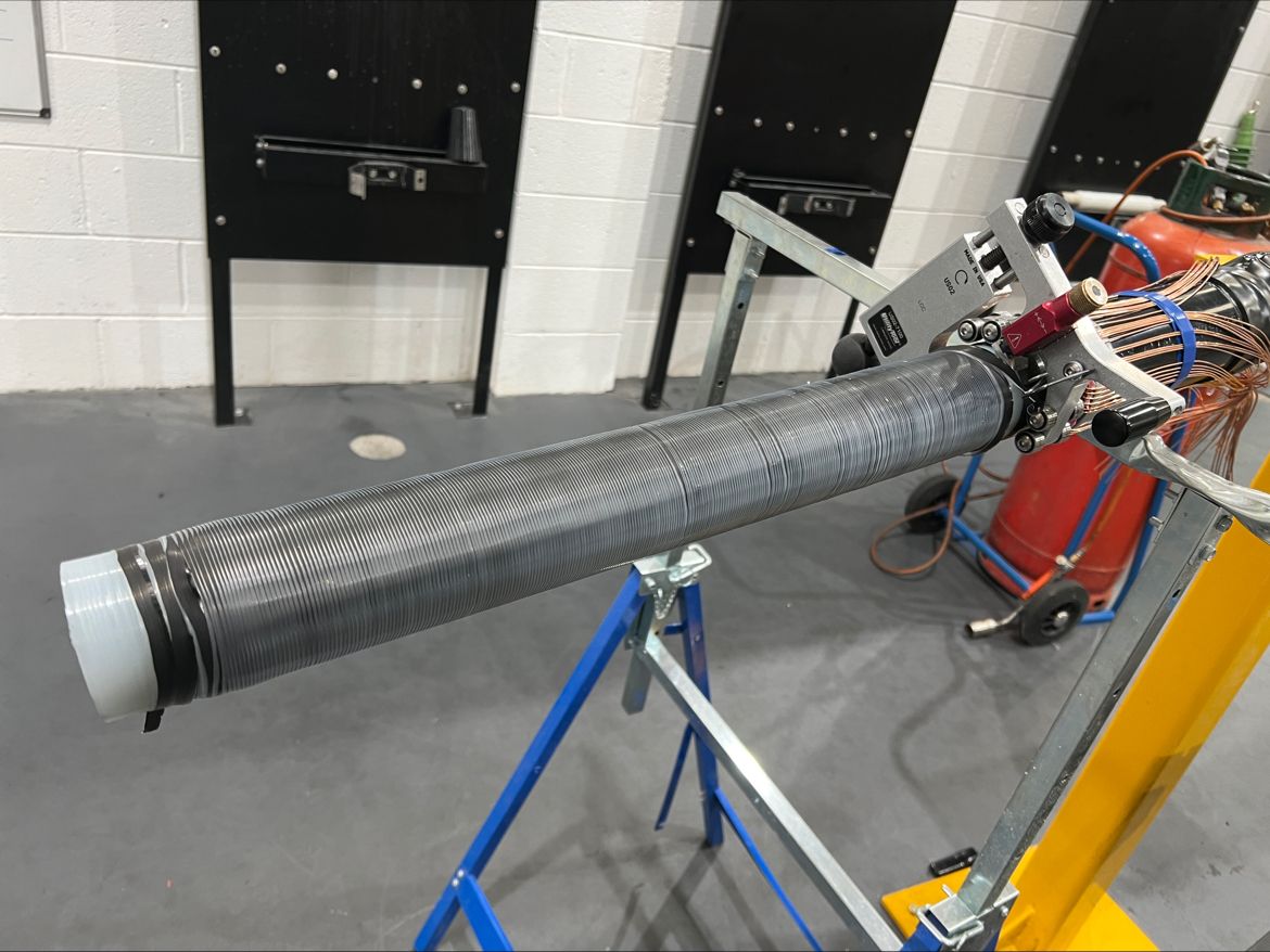
Cable Jointing Tools | 66kV IAC Inter-Array Cables
US02 MAX | here the Jointing Tool is shown here in use on the high voltage cable preparation of 66kV/72kV 1200sqmm single cable XLPE insulation with bonded semicon screen – minimal polishing and chamfering required with a clean and precise transition.
Cable Sheath & Lead Sheath Removal
Typically, Alroc cable sheath stripping pliers, PG types, would be used for removal of the outer cable sheath/jacket depending on the outside diameter of the cables to be jointed and terminated – these tools effectively strip the PE (polyethylene) sheath from medium/high voltage power cables. The lead sheath (Pb) is generally removed using jointers knives – the lead sheath should be carefully scored and then peeled from the cable.
Cable Insulation & Bonded Screen Removal
Note for larger diameter 66kV power cables, 300sqmm+, the standard 33kV cable preparation tools will be unsuitable – for removal of XLPE insulation with bonded screens we would recommend Alroc CAMF4/40-90 tool.
The 66kV Training Course utilises single core 300sqmm cables with a 48.1mm diameter over the bonded semicon screen – depending of jointers preference any semicon shaving tool from reputable manufacturers including Alroc, Ripley or Boddingtons could be used.
Similarly, any XLPE cable insulation removal tool suitable for 46.1mm primary insulation diameter cable could be used.
The preferred bonded screen stripping tool is used to leave various lengths of black insulation screen from the outer sheath cut and the measurement varies depending on the type of joint, termination or connector.

Chamfer | Groove | Shave – Alroc CAMF4/40-90-BBCF Multi-function 66kV Cable Tool
Chamfer & Polish

Aluminium Oxide
For the chamfer we would recommend the Alroc GRI tool along with conventional glass to achieve a smooth finish to the XLPE insulation – the cable insulation would then be polished using aluminium oxide abrasive strips, usually 180/240 grit and 400 grit.
The XLPE insulation must be polished smooth with an appropriate aluminium oxide grit paper until the XLPE surface is smooth and wrinkle-free. To finish this process, reverse the paper and “buff-up” with the smooth side.

Alroc GRI Tool
Cable Sanding Machines & Tools for MV HV Cables up to 130mm Diameter
Reducing Repetitive Strain & Improving Cable Preparation Processes
Typically 66kV Cable Specification
➡ The following cable specification is based on 66kV XLPE Insulated Lead Sheath Single Core 300sqmm cable to IEC 60840:
| Single Core Cable with Copper Round Compacted Conductor, XLPE Insulated, Lead Sheath, Polyethylene Oversheath | |
| 66kV Cable Code | 714242019533** |
| Standard Specification | IEC 60840 Generally according to NPS/002/022 |
| Type of Cable | XLPE/PB/MDPE |
| Rated Voltage Uo/U (Umax) | 38/66 (72.5kV) |
| Number of Cores x Nominal Cross-section | 1 x 300sqmm |
| Approximate Cable Overall Diameter | 59mm |
| Approximate Cable Overall Weight | 8.4kg/m |
| Nominal Drum Length (Tolerance) | 500m (-0%, +0%) |
Cable oversheath marking by embossing in two lines as follows:
- CABLEL 0317 2016 09* ELECTRIC CABLE 66000 VOLTS IEC 60840 1×300 CU ‘ref number’**
*Year and month of manufacture
** Insulation Core Lot number (8 digits by embossing and 2 last digits by indenting) - By ink – meter marking at on metre intervals
66kV Cable Structure
Cable Manufacturer Hellenic Cables S.A.

- Conductor:
Annealed bare copper round strand compacted class 2 BS EN / IEC 60228 of nominal cross-section equal to 300sqmm longitudinally waterblocked by waterblocking yarns and/or waterblocking tapes and/or waterblocking powder between conductor inner strands (approx diameter over 20.4mm) - Semiconductive tape applied helically with overlap
- Conductor non-metallic extruded screen:
Extruded semiconducting compound of 1.0mm nominal thickness (0.60mm minimum at any point thickness) - Insulation
XLPE super-clean according to IEC 60840 of 12.0mm nominal thickness (minimum average thickness of 11.0mm, minimum at point thickness 10.80mm – approx diameter over insulation 46.1mm) - Core non-metallic extruded screen:
Extruded semiconducting compound bonded to insulation of 1.0mm nominal thickness (0.60mm at any point of thickness) - Semiconductive waterblocking tape applied helically with overlap
- Metallic sheath:
Lead alloy type PK021S or other suitable alloy type according to EN 50307 of 2.0mm nominal thickness - Cable sheath
MDPE type ST& according to IEC 60840 of 2.7mm nominal thickness.
Sheath colour: Black - Extruded semiconducting compound serving as electrode for the DC voltage test of the oversheath

Pfisterer CONNEX | 3M Cold Shrink | Nexans Euromold | Nexans Slip-on | Heat Shrink Cable Terminations – stocked and distributed by Thorne & Derrick
Cable Innovation Tools & Accessories for Low & High Voltage Power Systems
THORNE & DERRICK are Specialist Distributors of LV HV Cable Jointing, Earthing, Substation & Electrical Eqpt up to 66kV – this includes the most extensive range of Ex Stock Innovation Tooling to facilitate safe and reliable preparation, termination and installation of cables.

Concentric & Split Concentric Cable Stripping Tools
August 8th, 2018
Alroc Tools – Cable Jointing Tools (LV MV HV)
-
uploaded by Chris Dodds - Thorne & Derrick Sales & Marketing Manager
Thorne & Derrick, Specialist Distributor of LV HV Jointing & Cable Installation Equipment are working with Alroc to improve the efficiency of cable preparation for Jointers working on LV MV HV electrical distribution systems.
The innovative Alroc DBT compact cable stripping tool is used by LV Jointers employed by NERS Accredited Independent Connection Providers (ICP’s) for the removal of the PVC outer cable sheath and primary insulation over the stranded copper or solid aluminium  conductor on BS7870 Concentric & Split Concentric cables.
These LV aluminium and copper cables are approved by UK Distribution Network Operators (DNOs) including Scottish Power Energy Networks (SPEN), Scottish & Southern Energy (SSE) and UK Power Network (UKPN).
Concentric and split concentric cables have been adopted as standard for use by DNOs to provide the final connection to residential properties. Additional cable functionality includes use for LV sub-main distribution and installation within high-rise buildings (LSZH Low Smoke Zero Halogen type) and street lighting systems.
The choice between Concentric and Split Concentric cable is determined by the supply type: TN-C-S supply for Concentric and TN-S supply for Split Concentric.
Concentric Cables
Concentric cables are used for power supplies with Protective Multiple Earthing (PME) systems, where a combined Protective Earth (PE) and Neutral (N) – together known as the PEN – connects the combined neutral-and-earth to real earth at multiple locations to reduce the risk of electric shock in the event of a broken PEN.
Split Concentric Cables
Split Concentric Cables are used when the power supply has separate PE & N conductors and are only combined as PEN near the power source. The Protective Earth and Neutral are not connected after the building entry point.
Jointers Tools
Alroc DTB cable end strippers enable the user to remove the outer sheath insulation of LV cable ranging from 16sqmm up to 150sqmm. The ruler engraved in the cable jointing tool sets the length of the XLPE insulation to be removed. The DTB cable end strippers are compact, light and heavy duty and are available for different cable sections – 16-25sqmm, 35-54.6sqmm and 70-150sqmm.
Alroc offer a range of low voltage cable preparation splicing and stripping tools suitable for use prior to cable joint and termination installation.
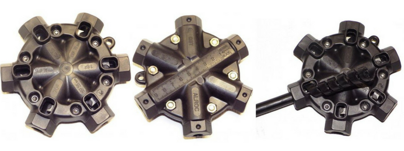
➡ Watch the following Video which demonstrates the ease and simplicity the Jointer can remove the cable sheath and insulation from the Concentric cables prior to installing the cable joints onto the distribution network.
Split Concentric & Concentric Cable Stripping Tool
♦ PDFs Courtesy & Property of Eland Cables

Alroc Tools are used and recommended by PFISTERER for MV HV cable preparation of cables prior to installation of their market-leading CONNEX plug terminations for connection to gas insulated switchgear and substations.
Thorne & Derrick
T&D are Specialist Distributors to UK Distribution Network Operators (DNO’s), NERS Registered Service Providers, ICP’s and HV Jointing Contractors of an extensive range of LV, MV & HV Jointing, Earthing, Substation & Electrical Eqpt – this includes 11kV/33kV/66kV cable joints, terminations and connectors for both DNO and private network applications.
Contact our UK Power Team for competitive quotations, fast delivery from stock and technical support or training on all LV-HV products.
Key Product Categories: Duct Seals | Insulated Tools | Cable Cleats | Cable Glands | Electrical Safety | Arc Flash Protection | Cable Jointing Tools | Cable Pulling | Earthing | Feeder Pillars | Cable Joints LV | Joints & Terminations MV HV

Alroc Cable Jointers Tool Kits – WPD Western Power Distribution Approved
July 5th, 2018
Alroc Cable Jointers Tool Kits – WPD
-
uploaded by Chris Dodds - Thorne & Derrick Sales & Marketing Manager
Alroc working with the Cable Policy Engineer at UK DNO Western Power Distribution have produced a customised cable jointers tool kit to enable the preparation of their medium/high voltage 33kV EPR type insulated power cables.
The Jointers Tools Kits are now standard issue to all WPD Apprentices upon completion of MV-HV jointer training.
The WPD Cable Jointers Tool Kit includes: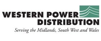
- Alroc PRG4 – Removes Outer Sheath Cable Jacket
- Alroc MF2/60 – Removes Cable Insulation
- Alroc CWB18/60 – Removes Bonded Semicon Screen
The cable jointing tools are supplied in a carry case with foam insert and additional space for tape measure, torque wrench, rasp file, shears and jointers depth knives (0.4mm and 0.6mm) – these items are available for separate purchase from Thorne & Derrick.
See also ➡ UKPN Polylam Cable Jointers Tool Kit – Alroc CPM-GB1
Alroc Tools – Cable Jointing Tools (MV HV)
Alroc Tools are used and recommended by PFISTERER for MV HV cable preparation of cables prior to installation of their market-leading CONNEX plug terminations for connection to gas insulated switchgear and substations.
Thorne & Derrick
T&D are Specialist Distributors to UK Distribution Network Operators (DNO’s), NERS Registered Service Providers, ICP’s and HV Jointing Contractors of an extensive range of LV, MV & HV Jointing, Earthing, Substation & Electrical Eqpt – this includes 11kV/33kV/66kV cable joints, terminations and connectors for both DNO and private network applications.
Contact our UK Power Team for competitive quotations, fast delivery from stock and technical support or training on all LV-HV products.
Key Product Categories: Duct Seals | Cable Cleats | Cable Glands | Electrical Safety | Arc Flash Protection | Cable Jointing Tools | Cable Pulling | Earthing | Feeder Pillars | Cable Joints LV | Joints & Terminations MV HV

Removal of MDPE Cable Oversheath From 33kV Cables Using Alroc PG Pliers
June 22nd, 2018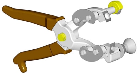
Alroc PG Pliers
-
uploaded by Chris Dodds - Thorne & Derrick Sales & Marketing Manager - Information Courtesy: CA3C/2 Relating to General Requirements for 33kV Cable Jointing (Western Power Distribution)
MDPE stands for medium density polyethylene – this material is used principally as a cable sheathing material on larger size conductor cables with higher voltage ratings, such as BS6622 11kV and 33kV power cables.
MDPE cable oversheaths must be removed from medium/high voltage cables with care using depth guarded jointers tools – incorrect use of tooling may cause damage to the underlying copper screen wires thus reducing the cross sectional area of the screen and its ability to carry fault current to which its designed.
Thickness of the oversheath should be of equal thickness at any point within the cable sheath of the MV HV power cable.
This may not always be the case and the use of specialised cable tooling may cause damage to the underlying copper screen wires, it is therefore, advisable to test on a scrap length of cable before jointing commences.
This applies to the installation of cable joints, terminations or connectors when using PG type cable stripping pliers manufactured by Alroc.
Removing Cable Sheath
Removal using the correct size of Alroc PG pliers according to the outside and overall diameter around the MDPE sheath.
- Adjust the depth of cutting blade in accordance with the thickness of the MV HV cable oversheath, there is a depth variation of 1, 2 or 3; try the depth of cut on the end of the cable or on some spare core
- Hold the Alroc PG pliers at 90° to the cable and place on the cable oversheath termination mark is, apply a slight pressure to the plier handle and rotate the Alroc pliers through 90°. This will create a full 360° circumferential cut in the oversheath of the 11kV/33kV cable
- Note – excessive hand pressure on the handles of the Alroc pliers will result in copper wire screen damage. This will place a 360° circumferential cut in the oversheath
- Remove and turn the stripping pliers so as they are parallel to the cable fit the cable between the support roller and cutting wheel
- Ensure the cutting wheel is placed to the waste side of the circumferential cut, apply a good pressure to the plier handle and pull the pliers longitudinally towards the cable end
- Using the claw blades at 90° to the cable, place the top blade into the cut line, apply pressure and pull down and away from the cut line, this will open the oversheath
| Alroc Tool Part Number | Cable Sheath Diameters | Tool Weight | Cable Tool Dimensions |
| PG1 | 8-22mm | 430g | 265 x 92 x 80mm |
| PG2 | 21-35mm | 500g | 265 x 92 x 80mm |
| PG3 | 26-52mm | 600g | 265 x 92 x 80mm |
| PG4 | 47-75mm | 840g | 300 x 109 x 104mm |
| PG5 | 55-95mm | 2000g | 360 x 140 x 160mm |
| PG6 | 80-130mm | 3000g | 515 x 195 x 200mm |
Should you require any technical support or field demonstration of Jointing Tools to remove the sheath, screen or insulation from LV MV HV cables please do not hesitate to contact Thorne & Derrick.
Alroc Tools – Cable Jointing Tools (MV HV)


