

Blog
Live Cable Joint – Triple Concentric PILC Cable (Street Lighting LV)
November 19th, 2018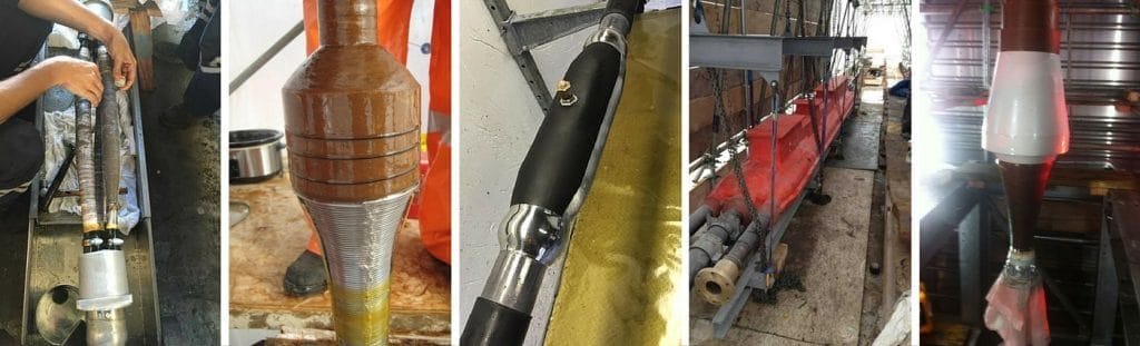
- Application: Triple Concentric PILC Cable (Street Lighting LV)
- Type: Live Cable Joint
- Cable Jointer: David Schofield – HV/LV Cable Jointer
-
by Chris Dodds T&D - estimated reading time 5 minutes
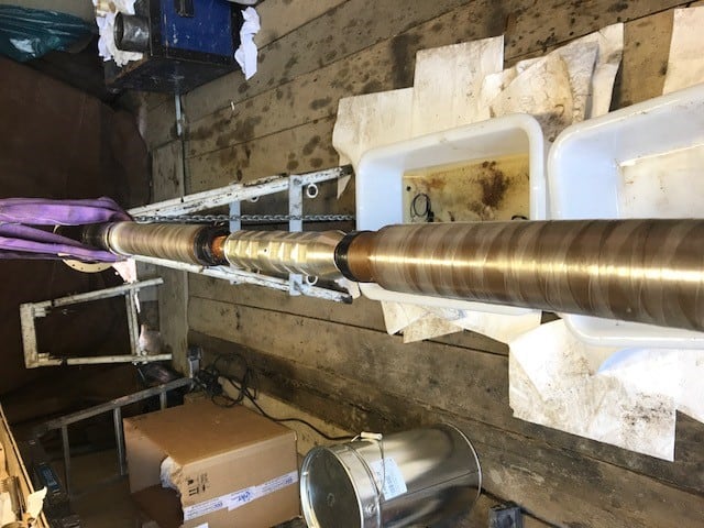
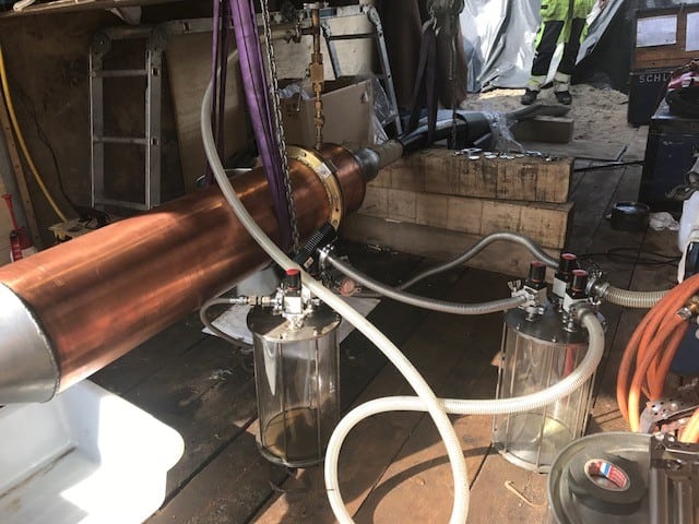
Today, we debut the skills and expertise of David Schofield, HV/LV Jointer. In the following commentary, David explains the cable jointing process when live cable jointing on LV low voltage cables.
Firstly, use a metal hack knife which is an essential hand tool in any cable jointers tool set to remove the steel tape armour from the cable to be jointed.
Use cable cleaning wipes to clean the lead cover and fit a 2-ended continuity bond to bridge the lead. Remove the lead and papers then fit a constant force spring around the lead – a cut is then applied to the 2nd part of the continuity bond around the outer concentric strands (neutral).
This enables the Jointer to cut the neutral in the middle of the cable joint – once cut form them back into a conductor and apply tape and reconnect with a Sicame connector with the single phase neutral included and the earths from both sides of the lead cut.
Next tape up just from the cable crutch of the neutral with Scotch 88 tape and remove papers. Next phase cut in the centre of the cable, this should be a live phase from into a conductor and Scotch 88 tape around the live strands which are live both ways. Now the reconnect with 2nd Sicame straight barrel and apply insulation patch. Tape next layer of papers from crutch to crutch and remove a section of tape and papers from the centre of this core revealing the inner phase. Install Sicame clamp connectors onto this core and with the single phase service core included apply rubber shroud onto this then apply water blocks. Finally, bond armours down and over protect the cable joint with the shell.
Live Cable Joint – Triple Concentric PILC Cable (Street Lighting LV)
Thorne & Derrick International
Should you require any assistance with the selection or specification of Prysmian cable joints please do not hesitate to contact us.
T&D distribute the most extensive range of MV & HV Cable Joints & Terminations, Cable Installation Accessories & Cable Pulling Equipment – we service UK and international clients working on underground cables, overhead lines, substation earthing and electrical construction at LV, 11kV, 33kV and EHV transmission and distribution voltages.
- Key Products: MV-HV Cable Joints & Terminations, Cable Cleats, Duct Seals, Cable Transits, Underground Cable Protection, Cable Jointing Tools, Feeder Pillars, Cable Ducting, Earth Tapes, Electrical Safety, Cable Glands, Arc Flash Protection & Fusegear.
- Distributors for: 3M, ABB, Alroc, BAND-IT, CATU, Cembre, Centriforce, CMP, Elastimold, Ellis Patents, Emtelle, Furse, Lucy Zodion, Nexans Euromold, Pfisterer, Polypipe, Prysmian, Roxtec.

LV – Low Voltage Cable Joints, Glands, Cleats, Lugs & Accessories (1000 Volts)

MV HV – Medium & High Voltage Cable Joints, Terminations & Connectors (11kV 33kV EHV)

Cable Laying – Underground Cable Covers, Ducting, Seals & Cable Pulling Equipment
More…
T&D’s Power Blog covers: LV MV HV & EHV Transmission & Distribution, Substations, Switchgear, Cable Jointing & Termination, Cable Fault & Repair, Underground Cables
➡ Visit Power Blog.

![]()
Jointers blog
Subscribe now to our POWER NEWSLETTER– a monthly email circulation packed with news, projects, videos, technical tips, training information, promotions, webinars, career opportunities and white papers.
Includes access to our popular JOINTERS BLOG with contributions from utility professionals, linesmen and cable jointers working on MV HV EHV cables and overhead lines typically at 11kV, 33kV, 66kV and up to 132kV.
15,000+ Subscribers. ➡ 
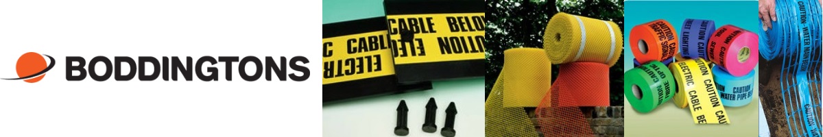
How To Install Detectamesh – The Warning Tape For Buried Cables, Pipes & Underground Services
November 19th, 2018
The Warning Tape For Buried Cables, Pipes & Underground Services
-
uploaded by Chris Dodds - Thorne & Derrick Sales & Marketing Manager
Boddingtons Detectamesh detectable underground warning tapes are a coloured plastic detectable mesh netting for cable marking and detecting buried underground pipes, electricity cables and utility services.
The underground warning tapes for marking electricity cables and utility pipes (gas and water) are available in a range of different colours and different texts available in 200mm x 100m for the protection and visual identification of electric, water and gas utility services.
Detectamesh
The following Blog explains the installation process of the Detectamesh mesh netting:
Step 1
It is recommended that the detectable mesh be buried halfway between the buried service (cable or pipe) and the surface of the earth.
Step 2
Unroll the Detectamesh onto the backfill in the cable trench or utility trench ensuring that it is earthed at both ends.
Step 3
Join the wires of rolls or cut lengths using Boddingtons crimps.
Step 4
Backfill the trench further to the surface.
Step 5
The detectable mesh can easily be detected down to one metre.
Step 6
Please consult Thorne & Derrick for further details of the exact depth your equipment can locate to.

Detectamesh Detectable Mesh Installation
BODDINGTONS CRIMPS & CRIMPING TOOL
Ensuring a continuous signal along the Detectamesh is vital – it is recommended to use the Boddington wire crimps and crimping tool. This gives the join sufficient strength to cope with most back fills into the trench. If it is not installed correctly then the signal may not pass from join to join.
Step 1

Crimping Tool & Stainless Steel Wire Crimps
Peel back the top tape at one end to expose the wire
Step 2
Insert the crimp over the wire on one of the mesh rolls. Push the wire right through so that about 5mm protrudes from the end
Step 3
Insert the wire from the other mesh into the crimp
Step 4
Crimp the joint together using the crimping tool
Step 5
Check that you have a strong connection by pulling firmly on the two ends. If the wire comes out, make the connection again
Step 6
The Detectamesh can now be laid and the trench back filled
Boddingtons | Detectamesh | Utilitape Underground Warning Tapes | Cable & Pipeline Protection Mesh | Plastic Cable Protection Covers
Cable Pulling Equipment
Thorne & Derrick distribute an extensive range of Cable Pulling & Laying Equipment to enable the safe installation of fibre and copper cables within the telecommunications industry. Safely installed cables reduces operational and maintenance requirements to the network and reduced service interruption to telecom cables, wires, ducts, cabinets and exchanges – products include cable spiking tools, conduit rods, cable lubricant, cable socks and cable rollers.

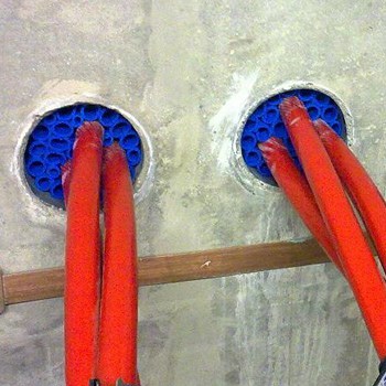
RISE Cable Transit Systems – Fireproof, Watertight & Gastight Sealing Of Cable Duct & Pipe Entries
November 19th, 2018
Sealing Cable Ducts (Water Tight & Gas Tight)
-
uploaded by Chris Dodds - Thorne & Derrick Sales & Marketing Manager
The effective sealing of cable ducts and pipe entries is critical to reducing risks; fire; flooding; explosion; environmental; confined space and corrosion of equipment.
All cable and pipe entries should be sealed according to the degree of fire resistance (if any) both integrity (E) and insulation (I), and watertight and gastight integrity prescribed for the respective element of the construction before penetration. In additional for bund walls and plinths it should be resistant to transformer oil.
Where the cable transit system also provides fire protection and/or prevents migration of flammable gas into a hazardous area or gas insulated substation it is now a legal obligation for the specifier, owner or main contractor to ensure a contractor can prove competency for the materials used, or the works to be carried out. (See Appendix A – Fire & Your Legal Liability- produced by Association for Specialist Fire Protection).
Any pipe or cable transit sealing system, such as those manufactured by CSD Sealing Systems, must satisfy the regulatory requirements of the following standards;
- BS 7671:2008 IEE Wiring Regulations (17th Edition) – 527.2 Sealing Of Wiring System Penetrations
- The Building Regulation/Standards
- Dangerous Substances & Explosive Atmosphere Regulations 2002 (DSEAR) & ATEX Confined Space
- The Regulatory Reform (Fire Safety) Order 2005
- Construction, Design and Management Regulations 2007 (CDM 2007)
Further relevant details of these can be found within Appendix B.
To reduce the risk (and provide a safety margin) of flooding, explosion, environmental leakage of transformer oil, confined space, high humidity and corrosion of equipment the penetration system should be;
- Certified watertight to 1.5 bar (21psi)
- Certified gastight to 1 bar (14psi)
- Age tested for in service life of 50 years
- Resistant to transformer oil
- Resistant to methane, hydrogen sulphide and chlorine.
- Permit thermal movement of the cable or pipe and still maintain a seal
When a cable or pipe system penetrates an element of the building or substation construction which has a specified fire resistance the penetration should be sealed using a suitable transit or seal product that will reinstate the fire resistance taking account of both the integrity and insulation performance required.
To prove the fire resistance the penetration system must be Third party certified to the new more stringent BS EN 1366-3, fire resistance tests for service installations; penetration seals (this will become mandatory end of 2012) and performance classification of the resistance to fire, the duration of both Insulation (I) and Integrity (E), in accordance with BS EN 13501-2.
RISE Water & Gas & RISE Fire, Water & Gas
BSEN 1366-3 also includes mechanical stability testing to ensure the system withstands the stresses which may arise when the support to the wiring system is damaged during a fire thus satisfying the mechanical stability requirements of IEE Wiring Regulations.
To satisfy all these requirements the following methods are recommended;
- CSD RISE Water & Gas (RISE WG) sealing system is used for non fire rated areas
- CSD RISE Fire, Water & Gas (RISE F) sealing system is used for fire rated areas
The RISE WG cable and pipe transit sealing system will provide; a minimum of 1.5 bar (21psi) watertight seal, 1bar (14psi) gastight ensuring compliance with both DSEAR and ATEX regulations as dangerous gases will be prevented from migration between hazardous area zoned areas RISE is resistant to methane, chlorine and hydrogen sulphide, reducing the risk of dangerous atmospheres in confined spaces.
Resistant to transformer oil, permits thermal movement of the wiring system without reduction of the sealing quality and is age tested to prove an in service life of at least 50 years without any deterioration in performance.
In areas that do not require a full fire rating the system should consist of 60mm RISE (RISWAT) rubber sleeves and FIWA fire rated, water and gastight sealant.
A suitable fitting RISE sleeve should be placed around each cable to ensure cable separation (critical for obtaining watertight and gastight integrity) and then use the remaining sleeves to tightly pack any free space in the penetration using sleeve sizes 27/19 and 18/12.
Push all of the filler sleeves into the opening, leaving 20mm free space at the front for the application for the sealant layer. Before sealing the penetration use an approved cable cleaner or degreaser to ensure that the surfaces of the cables and the penetration sleeve are clean and free from any dirt, oil or dust residue.
The cable sealant is then applied to the face of the penetration ensuring a pressure tight seal is maintained, sealant must be applied to a minimum depth of 20mm.
CSD Rise Rapid
Cable Duct Sealing Installation Video
The following video demonstrates the installation process of the CSD RISE Rapid method of sealing cable ducts and pipe penetrations or entries.
The RISE Fire rated system (RISE F) provides the same level of protection as RISE WG but in addition will maintain the fire protection of any wall, floor or partition when it is penetrated by any cable or pipe transit. It provides up to 240 minutes (4 hours) of fire integrity (E) and 120 minutes of fire insulation (I) as classified in accordance with BS EN13501-2.
The cable duct sealing system also provides mechanical stability to withstand the stresses which may arise through damage to the support of the wiring system due to fire.
For a full fire rated system this should consist of 160mm RISE fire resistant rubber sleeves and a layer of FIWA fire rated, water and gastight sealant at each end of the penetration.
A suitable fitting RISE sleeve should be placed around each cable to ensure cable separation and then use the remaining sleeves to tightly pack any free space in the penetration using sleeve sizes 27/19 and 18/12.
Push all of the filler RISE sleeves into the opening, leaving 20mm free space at the front and back of a 200mm long penetration for application of the sealant layer. Before sealing the cable or pipe penetration ensure that the surfaces of the cables and the penetration sleeve are clean and free from any dirt, oil or dust residue.
The RISE sealant is then applied to each face of the penetration ensuring a pressure tight seal is maintained, sealant must be applied to a minimum depth of 20mm.
In areas where access is only possible from one side of the penetration it may be possible to install a single 40mm layer of FIWA sealant at the accessible side of the penetration.

RISE Duct Seal – Watertight and gastight protection for building entries and cable duct terminations
Appendix A
Fire & Your Legal Liability
Why is this of relevance to me!
If you are involved in provision of a fire protection package, at any level, then you share liability for its usefulness and its operation when it’s needed in fire, and that liability will still be there in the event of a court case.
I place the order; it is not my responsibility to install the works!
If it is your responsibility to specify the cable protection and sealing materials and/or appoint the installation contractor, it is also your responsibility to ensure that they can prove competency for the fire protection materials used, or the works to be carried out.
It’s no longer simply a duty of care or voluntary – it’s a legal obligation.
If you knowingly ignore advice that leads to a failure in the fire performance of any element of installed fire protection within a building, then you are likely to be found to be just as culpable as the deficient installer.
You share liability for the provision of information required under Building Regulation 16B that tells the user of the building about the fire prevention measures provided in the building. Otherwise, the user cannot make an effective risk assessment under the Regulatory Reform (Fire Safety) Order 2005.
What is expected of me?
In the event of fire, and deaths, a court will want to know how every fire protection system was selected; the basis for selection of the installer, whether adequate time was provided for its installation, and whether there was adequate liaison between the different parties to ensure it was installed correctly. No ifs, no buts – it’s all contained in the Construction, Design and Management Regulations 2007.
The CDM 2007 regulations, enforced by Health and Safety Executive concentrate on managing the risk, and the health and safety of all those who build, those that use the building, those who maintain it and those that demolish it – cradle to grave.
Be aware – the time to consider the above is before the event, not after it!
Provided by: The Association of Specialist Fire Protection
Cable Duct Seals – Sealing Cables Against Water, Gas & Fire
The below video shows the cable duct seals providing an effective and simple solution to all fire, gas and water tight duct sealing requirement.
Appendix B
The requirements for Sealing of Cable and Pipe entries are covered in more detail in the following regulations:-
1) BS 7671:2008 IEE Wiring Regulations (17th Edition) 527.2 Sealing of wiring system penetrations.
527.2.1 Where a wiring system passes through elements of building construction such as floors, walls, roofs, ceilings, partitions or cavity barriers, the openings remaining after passage of wiring system shall be sealed according to the degree of fire-resistance (if any ) prescribed for the respective element of building construction before penetration.
527.2.7 Any cable sealing arrangement intended to satisfy Regulation 527.2.1 or 527.2.2 shall resist external influences to the same degree as the wiring system with which it is used and, in addition, it shall meet all of the following requirements:
- It shall be resistant to the products of combustion to the same extent as the elements of building construction which have been penetrated
- It shall provide the same degree of protection from water penetration as that required for the building construction element in which it has been installed.
- It shall be compatible with the material of the wiring system with which it is in contact
- It shall permit thermal movement of the wiring system without reduction of the sealing quality.
- It shall be of adequate mechanical stability to withstand the stresses which may arise through damage to the support of the wiring system due to fire.
The cable seal and wiring system shall be protected from dripping water which may travel along the wiring system or which may otherwise collect around the seal unless the materials used in the seal are all resistant to moisture when finally assembled for use.
2) Building Regulations in England & Wales
Approved Document B 2006 – Building Regulations 2000
Section 10.2 of approved document B3
“If a fire separating element is to be effective, then every joint, or imperfection of fit, or opening to allow services to pass through the element, should be adequately protected by sealing or fire stopping so that the fire resistance of the element is not impaired”
Regulation 16B as referenced in Appendix G -Approved document B – Fire safety Appendix G of the Approved Document B, 2006 Edition, introduced comments on a new Regulation 16B of the building Regulations 2000, which requires that where work involves the erection or extension of a relevant building, or a relevant change of use of a building, then fire safety information shall be given to the responsible person at the completion of the project, or when the building or extension is first occupied.
Fire safety information’ means information relating to the design and construction of the building or extension, and the services, fitting and equipment provided in or in connection with the building or extension, which will assist the responsible person to operate and maintain the building with reasonable safety.
3) Building Standards Scotland
Regulation 12.1 of the Building standard states that every building shall be so constructed, that for a reasonable period in the event of fire-
- its stability is maintained
- the spread of fire and smoke within the building is inhibited; and
- the spread of fire to and from other buildings is inhibited.
Regulation 9 stipulates that the requirements can be satisfied only by compliance with the relevant standards which are set out in a series of Technical standards; section 3 of the introduction to Technical Standard D states:-
“ To restrict the internal spread of fire, a building may have to be divided into compartments separated from each other by compartment walls or compartment floors intended to provide a complete barrier to fire between the compartments. In practice, the continuity of such walls and floors will have to be breached by openings for circulation or services and where this occurs special precautions are necessary to maintain the effectiveness of the barrier. The acceptable size of a compartment for this purpose is determined by its likely fire load which is, in turn, influenced by the purpose group of the building, or part of the building, in which it is situated and the provision, or otherwise, of active fire protection measures.”
4) The Regulatory Reform (Fire Safety) Order 2005
Came into effect on 1st October 2006 and applies in England & Wales.
Similar legislation applies in Scotland and in Northern Ireland. The new system of regulation is risk-assessment based and includes the provision that the person responsible for the premises should carry duties for fire safety therein. Risk assessment by the ‘responsible person’ is a vital part of the planning process.
5) Construction, Design and Management Regulations 2007 (CDM 2007)
CDM Regulations 2007 came into effect 6 April 2007 and is enforceable under criminal law.
In brief, government intends that health and safety is integrated into the management of a project and encourages everyone to work together to achieve that objective as a normal part of a project, to reduce risks and manage the residual risks, by use of the right people for the right job at the right time. This shall enable hazards early on such that they be removed, reduced or managed properly.
CDM co-coordinator industry guidelines – produced by Construction Skills
www.cskills.org/healthsafety/cdmregulations
www.cskills.org/uploads/CDMCo-ordinatorstcm17-4642.pdf
6) Fire Test Standards
Hitherto ad hoc fire testing of penetration product has been performed to BS476 Part 20 & 22:1987, however BS476 series of tests is being withdrawn for use, it is now recommended that to ensure full compliance only those products that are 3rd party certified are used and preferably those that have been tested to the new more stringent BS EN 1366-3, fire resistance tests for service installations; penetration seals ( this will become mandatory end of 2012) and performance classification of the resistance to fire (both insulation and integrity) in accordance with BS EN 13501- 2 .
BSEN 1366-3 also includes mechanical stability testing to ensure the system withstands the stresses which may arise when the support to the wiring system is damaged during a fire.
7) Dangerous Substances & Explosive Atmosphere Regulations 2002 (DSEAR) & ATEX Explosive Atmospheres – Preventing the formation of a dangerous atmosphere through the migration of gases through cable and pipe transits in walls, floors and partitions.
T&D distribute proven cable duct sealing products from leading manufacturers CSD Sealing Systems with widespread utility approvals and industry acceptance as trusted alternatives to traditional “sticky and tricky” to install mastic seals or regulation violating expanding foam – these duct seal products are technically advanced cable sealing solutions designed to provide guaranteed protection of clients assets without the risk of failure.

Duct Seals – Sealing Cable Ducts

Pfisterer CONNEX | 3M Cold Shrink | Nexans Euromold | Nexans Slip-on | Heat Shrink Cable Terminations – stocked and distributed by Thorne & Derrick
Jointing Oil Filled EHV Cables Using NKT Fluid-Filled Accessories
November 18th, 2018
- Application: Jointing Oil Filled EHV Cables Using NKT Fluid-Filled Accessories
- Cable Type: Oil Filled EHV Cables
- Cable Jointer: Dean Wilson Owner Director at D C Jointing Ltd
- Featured Manufacturer: NKT Cables
NKT Cables & Accessories
Crimping
Chamfering

Vacuum & Filling
NKT cable Joints & Terminations Overview 
- Outdoor cable terminations (porcelain or composite)
- Non-self-supporting outdoor cable terminations
- Cable terminations for gas-insulated switchgears (GIS)
- Transformer cable terminations
- Straight-through cable joints
- Insulating joints/cross-bonding cable joints
- Transition cable joints, XLPE-insulated/oil-filled cables
- CabSnap accessories for preassembled cable connection systems
NKT Cable Joints
NKT has a broad portfolio of low-pressure oil cable sets up to 170kV: from through and stop sockets to end closures and transition sleeves for connection to modern VPE technology.
For the quality and safe installation of NKT cable sets a wide range of Jointer Training is provided so that utilities can continue to operate oil cable systems cost-effectively. In addition, NKT supports clients in setting up a local reserve warehouse to ensure rapid availability of high voltage cable joints.
Renew, rebuild and repair of high voltage low pressure oil filled cables with NKT.
NKT Straight Three Piece Joints – Cross Bonding Cable Joints
High Voltage Cable Accessories 72kV to 245kV
Should you require any assistance with the selection or specification of cable joints or terminations please do not hesitate to contact us.
Thorne & Derrick Specialist Electrical Distributor
LV ♦ MV ♦ HV
T&D distribute the most extensive range of LV, MV & HV Cable Jointing, Terminating, Installation & Cable Pulling Equipment – we service UK and international clients working on underground cables, overhead lines, substations and electrical construction at LV, 11kV, 33kV and EHV transmission and distribution voltages.
- Key Products: MV-HV Cable Joints & Terminations, Cable Cleats, Duct Seals, Cable Transits, Underground Cable Protection, Cable Jointing Tools, Feeder Pillars, Cable Ducting, Earthing & Lightning Protection, Electrical Safety, Cable Glands, Arc Flash Clothing & Fusegear.
- Distributors for: 3M, ABB, Alroc, Band-It, Catu, Cembre, Centriforce, CMP, Elastimold, Ellis Patents, Emtelle, Furse, Lucy Zodion, Nexans Euromold, Pfisterer, Polypipe, Prysmian, Roxtec.
LV – Low Voltage Cable Joints, Glands, Cleats, Lugs & Accessories (1000 Volts)
MV HV – Medium & High Voltage Cable Joints, Terminations & Connectors (11kV 33kV EHV)
Cable Laying – Underground Cable Covers, Ducting, Seals & Cable Pulling Equipment
More…
T&D’s Power Blog covers: LV MV HV & EHV Transmission & Distribution, Substations, Switchgear, Cable Jointing & Termination, Cable Fault & Repair, Underground Cables.
➡ Visit Power Blog
Cable Spiking High Voltage Cables – UK Power Networks
November 14th, 2018
Cable Spiking High Voltage Cables – UK Power Networks
- Information Courtesy – UK Power Networks
8.13 Procedure for Spiking Cables
Following the identification of a cable, the cable will then need to be spiked using a cable spiker to ensure that it is not Live at HV. The following procedure shall be followed:
- If the process has not already necessitated a Sanction-for-Test, then a SFT must be obtained from Control (A SFT cannot be issued for idle or abandoned cables that are not part of a network, as Circuit Main Earths cannot be applied)
- If the cable has been identified by signal injection, it is not necessary to disconnect the instrument and re-apply the Earth
- The consent of the Control Engineer must be obtained prior to spiking
- Spike the cable
- Call Control and ask if any alarms have been received
- Before the spiking gun is removed, at least one of the verification tests, given below, must be conducted
- Following a positive result of the verification test, the earths will be re-applied and remain applied whilst the spiking gun is removed under the SFT and under the Personal Supervision of the recipient of the SFT. (this does not preclude the option of the SAP to issue a PTW to remove the spike gun)
- Furthermore, under the same SFT and following the removal of the spiking gun, the cable may be opened and stripped for phase colour tests to be made under the Personal Supervision of the recipient of the SFT (this does not preclude the option for the SAP to issue a PTW to open and strip the cable)
- SFT to be cancelled and a Permit-to-Work shall be issued for work to commence on the cable.
Injected Signal Strength Verification
Listen to the signal on either side of the spiking gun.
The signal strength on the side on which the signal is being injected should be distinctly louder than that on the furthest side. This is because the spike driven into the cable will be providing a short-circuit route for the signal. Therefore much less signal, if any, will flow to the end of the cable where the circuit main earth has been applied.
Verification by Insulation (Megger) Testing.
Prior to spiking, remove all the Earths and megger the cable. The cable can be tested between phases and between phase to Earth.
The tests should show healthy insulation values.
After spiking, test the cable again. The results should show a faulty cable, thus proving that the correct cable has been spiked.
Why Must Control be Contacted Before Spiking?
It is a requirement of DSR 5.9.2.
The consent of the Control Engineer must be obtained before spiking, to alert their attention that an incorrect spiking may have occurred, if an alarm is received.
The Control Engineer also has a final opportunity to prevent the spiking, if a feeder trips on the network in that vicinity. The circuit may be required to support the load and so the job may have to be postponed.
Why Must Control be Contacted After Spiking?
It is a requirement of DSR 5.9.2.
The Control Engineer must be contacted after spiking, so that a check may be made for any alarms that could be linked to the spiking. The Control Engineer may need to check with other Control Engineers. This is because there have been occasions when cables have been incorrectly spiked and the alarm has been received and accepted by another Control Engineer and not communicated to the Control Engineer dealing with the cable spiking.
8.14 Spiking Requirements of Circuits Comprising of Single Core Cables
In normal circumstances the spiking gun should be applied such that all three cores are spiked. However in the following circumstances it is essential that all three cores are spiked:
- 11kV Networks with Arc Suppression Coils
- 11kV Networks fed from Unganged Fuses
- Pot / Stop Ended Circuits
General
There may be occasions [excluding (i), (ii) or (iii) above] where it is only required to work on one or two of the single core cables. It would therefore be undesirable to spike and damage all three.
If only one or two of the single core cables are to be spiked, then insulation tests before and after spiking shall be conducted, to confirm that the correct circuit has been spiked. It will be necessary to use an instrument that applies a sufficiently high voltage, to detect the damaged caused by the spiking. This is necessary, as the single core cables may be completely severed by the spike and may appear as an open circuit (and therefore healthy), if the voltage applied by the instrument is too low.

PICOUP 400 Hydraulic Cable Spiking & Cutting Tool
Cable Spiking & Cutting Tools | Check Voltage Absence on LV MV HV Power Cables
Hydraulic & Remote | Suit SWA Cables up to 140mm Dia | More info PICOUP 400
8.15 Re-location of point of work
Following the positive identification and spiking of a cable, it may be necessary to change the point of work after issuing a Permit to Work e.g. when dampness testing. This may be done, without reference to the Permit issuer, and without the need for further spiking, provided that the Permit holder can physically trace the cable by means of a running noose from the initial point of work, to the new point of work.
➡ Thorne & Derrick distribute Cable Spikers for low, medium and high voltage electrical systems, typically used to spike 11kV-33kV power cables – we provide competitive prices for cartridge and hydraulic type cable spiking tools from stocks to UK and international destinations.
Since 1985, T&D have established an international reputation based on SERVICE | INTEGRITY | TRUST.
Contact us for 3M Electrical, ABB, Alroc, AN Wallis, CATU Electrical, Cembre, Centriforce, CMP, CSD, Elastimold, Ellis Patents, Emtelle, Euromold, Filoform , Furse, Lucy Electric & Zodion, Nexans, Pfisterer, Polypipe, Prysmian, Roxtec, Sicame, WT Henley.

Invitation
Thorne & Derrick invite you to join LinkedIn’s largest LV-HV Electrical Discussion Group : Low & High Voltage Power, Cabling, Jointing & Electricals. Discussion subjects include cable installations, cable jointing, substation, overhead line and electrical construction at LV, 11kV, 33kV and EHV. Network, engage and promote your profile, company or products with over 10,000 influencers.


