BASEC is an independent accredited certification body for the cable industry worldwide.
BASEC’s name is synonymous with cable quality and safety.
Although present everywhere, cables seldom impact their users; they are usually hidden from view, and, if they are fulfilling their role correctly, require no attention. They should perform reliably for many decades if they have been correctly specified, conform to relevant standards and specifications, carry BASEC or another recognised approval, and have been carefully maintained. Protection from environmental and mechanical stress is also essential.
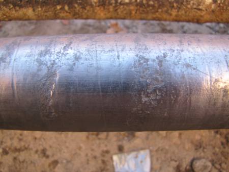
However, even cables that are sourced responsibly are at risk during initial delivery and installation. During this phase, they will be subjected to movements, stresses and strains – and if these exceed the cable design limits, damage becomes a strong possibility. Even simple issues like snagging on sharp edges can have serious consequences.
Installation damage during the cable pulling and laying process can lead to customer dissatisfaction, significant delays in project completion, extra resources being needed, and in particular, additional costs imposed on installers for removing and replacing damaged cables. These problems can be exacerbated if the effects of any damage do not become apparent, potentially affecting the supply of power, control or communications, until after the installation has gone into service.
Below are some top tips for a clean, trouble-free installation:
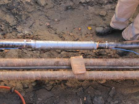
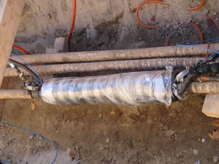
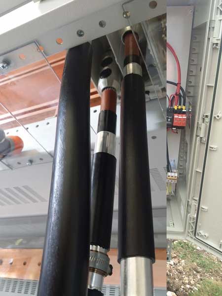
Cable delivery and cutting to length: Safe handling of cable starts with the supplier, often a distributor or wholesaler. Manufacturers will deliver cables on an appropriately sized drum or reel, loaded under controlled factory conditions. Cutting the cable to length, and redrumming onto an often-smaller delivery drum can result in over-bending if the drum belly diameter is too small; additionally, the cable may suffer external scuffing damage.
End caps: If suitable end caps are not fitted onto the cut length, water may penetrate the cable during storage or on site.
Bend radius – armoured cables:Bend radius is a key consideration, particularly for SWA cables and for higher voltages of 11kV or more. Minimum bend radius is generally defined by cable standards, or is advisory; it should be communicated by manufacturers and passed on by suppliers to the installers. Sometimes two figures are used; a dynamic radius for the pull, and a possibly smaller final static radius for when the cable is no longer under tension.
Maximum cable tension and sidewall pressure limits can both cause damage if exceeded when pulling cables. To prevent this, cable installation routing should be closely assessed, and several rollers or guides used at any bend points. A single cable roller or guide’s external radius is always likely to be much lower than the cable’s minimum bend radius. As a simple rule of thumb, for a four-core armoured cable larger than 40mm OD, a full-sized bicycle wheel should fit within the bend.
Bend radius – screened cables: With screened cables such as BS 7629-1- rated fire alarm types, the minimum bend radius must be maintained to ensure fire integrity. Kinks in the screening or over-tight entry into accessories may compromise fire performance. All such cables will have been fire tested at a specified bend radius, which the manufacturer should communicate to their suppliers and users.
Bend radius monitoring:Monitoring the bend radius on site is not straightforward. Many installers use simple go / no-go templates, but these can sometimes miss the tight parts of bends. Purpose-designed radius gauges can measure extremely accurately, providing reassurance that a cable installation has been completed correctly and safely.
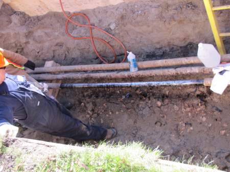
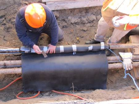
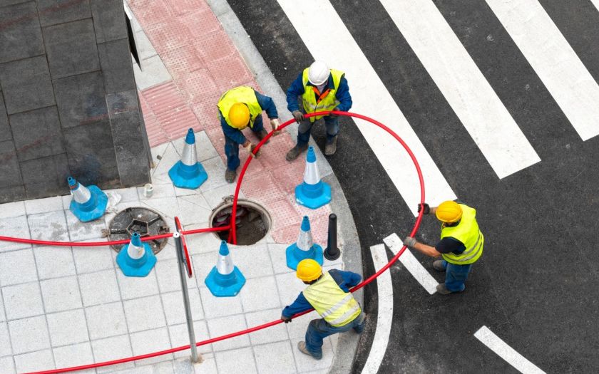
Cable pulling: Problems can occur where cables are pulled in two directions from a common mid-point. Some cable is initially pulled in one direction, then the remaining cable is laid out from the drum before being pulled in another direction. This approach can cause significant damage to a cable that cannot twist freely during installation, or where loops of cable introduce twists. Damage to armour can result in bird-caging and sheath splits.
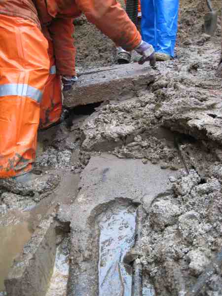
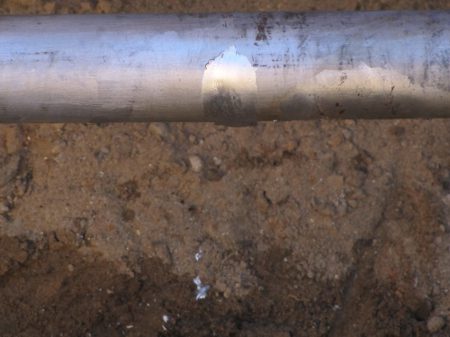
Workers pulling cable across pipes to supply energy to a neighbourhood
Avoiding cable torsion when pulling is important, and is largely addressed by using rotating pulling heads and a suitable cable pulling sock. Pulling the cable through a rope will restrict rotation and can create problems. Tension built up around each bend will propagate back down the cable, causing issues nearer the drum.
Conclusion
Competent and experienced cable installation teams, using the correct equipment including tension-monitored winches, pulling socks, and a generous quantity of rollers and guides, should experience fewer problems while ensuring a trouble-free installation.
Top 10 Articles | Thorne and Derrick & BASEC #CABLEQUALITY
With a shared passion and ambition to enhance electrical safety through the education and encouragement of industry stakeholders to specify and buy accredited, tested and certified Quality Cables & Cable Accessories.
#CableQualityis the hashtag – securing public safety through the specification and installation of BASEC approved and verified LV MV HV electrical cables by competent and qualified electricians is the objective.
Thorne & Derrick distribute an extensive range of Cable Pulling & Laying Equipment to enable the safe installation of fibre and copper cables within the telecommunications industry. Safely installed cables reduces operational and maintenance requirements to the network and reduced service interruption to telecom cables, wires, ducts, cabinets and exchanges – products include cable spiking tools, conduit rods, cable lubricant, cable socks and cable rollers.
Solution to Terminating & Connecting Photovoltaic Solar Aluminium Cables
uploaded by Chris Dodds - Thorne & Derrick Sales | Marketing Manager
Pfisterer Sicon Cable Lugs
Cable Lug Installation
Bolted mechanical cable lugs should only be installed by qualified and trained specialist personnel.
The cable lug installation must be carried out in dry and clean conditions.
Pfisterer Sicon cable lugs are specially designed for both copper and aluminium conductors with range taking acceptance of conductors, rated up to 72kV.
Cable lugs, straight connectors, branch connectors (with or without oil stop/water block) are available for the connecting and jointing of LV-HV cables.
5 Key Safety Rules For Pfisterer Sicon Installation
Covering caps are not heat resistant. Do not use with heat shrink material.
Pfisterer Sicon Cable Lugs & Solar PV Cables
Demo Video
DC string solar panel and combiner to inverter connection cables can be effectively terminated using Pfisterer Sicon cable lugs. In the following video the Pfisterer Sicon cable lug is secured in place using the Boddingtons Connector Holding Tool and then installed in seconds using a Milwaukee impact wrench.
LEONI Studer AG is based in Switzerland, founded since 1939 and is part of the LEONI Group which has been around since 1569 manufacturing gold wires for over 400 years.
PV Solar Aluminium Power DC Cable. BETAflam® Solar Cable
Pfisterer Sicon Cable Lug 332-605-011
Sicon In Solar – Pfisterer Project Experience
By Steve Cooper (Pfisterer UK Sales Engineer)
“Just under a year ago Pfisterer received a call from a major UK solar EPC who were looking to use aluminium cable on the upcoming round of projects. They had major concerns with oxidisation of aluminium conductors – the technical benefits of Sicon soon brushed these issues aside. Usually my work would be done now the specification would be in place and I would move on to my next project.
Not this time, the next issue was the combiner box (these combine the strings from the solar panels with a DC output). The combiner boxes were fitted with a pressure plate connection that was not suitable for aluminium conductors.
After many conversations with the combiner box manufacturer the only solution was to offer a Pfisterer 332 601 010 (10-95sqmm Sicon mechanical through connector) and a heatshrink joint to connect the aluminium conductor to a 50sqmm flexible copper conductor. The substation was quite simple in comparison, the customer purchased Pfisterer 332 604 010 (10-95sqmm Sicon cable lugs) used in conjunction with heatshrink cable lug seals.
Pfisterer Sicon cable lugs and connectors are now established into the solar industry.
As project installations transfer from copper to aluminium cable systems the requirement for mechanical shearbolt connectors, manufactured from aluminium alloy, has risen fast.
Since their introduction, Sicon connectors and lugs have been used by a host of major solar EPC’s and installers. Pfisterer have built up an extensive knowledge of the solar industry and have been involved in many technical conversations with investors, contractors and solar equipment manufacturers.
The rewards of solar can be great with over 20,000 Pfisterer Sicon units sold over the last 6 months in the UK alone. An average installation uses 30+ Pfisterer lugs per M.W. With an estimated UK market for 2015 of 3.2GW and globally 53GW then the future looks bright for Sicon.”
The First Cable Connector System With Stepless Shear Bolts
What Is a Combiner Box?
The combiner box’s role is to bring the output of several solar strings together. Daniel Sherwood, director of product management at SolarBOS, explained that each string conductor lands on a fuse terminal and the output of the fused inputs are combined onto a single conductor that connects the box to the inverter.
“This is a combiner box at its most basic, but once you have one in your solar project, there are additional features typically integrated into the box,” he said. Disconnect switches, monitoring equipment and remote rapid shutdown devices are examples of additional equipment.
Thorne & Derrick distribute the most extensive range of Cable Installation & Electrical Distribution Equipmentto the renewable energy sector – we service UK and international clients working on underground cables, overhead lines, substations and electrical construction at 11kV and up to and EHV transmission and distribution voltages.
uploaded by Chris Dodds - Sales & Marketing Manager | Thorne & Derrick
All Images Courtesy Of: Douglas Page (Instructor & Cable Splicer at Hydro One Training and Development Services).
Douglas Page is not a stranger to our Jointers Blog having blazed a trail over the past few weeks with some real ripsnorting, hardcore, high voltage images.
Let’s treat ourselves to a quick whistlestop tour of Doug’s recent contributions to the Jointers Blog as an appetite whetter to the latest serving up of his captivating EHV skills.
115kV Straight & Stop Joint On LPLF, PILC Cables In Cable Vault
EHV Cable Splicing – 115kV Stop Joint (Taped)
Jointing 44kV High Voltage Submarine Cables Using 3M Cold Shrink Splices
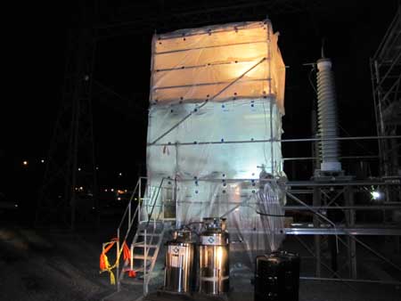
Water Treeing in High Voltage Cables : A 230kV HPPT Termination Repair
Time for the Main Course. Bon Appetit…
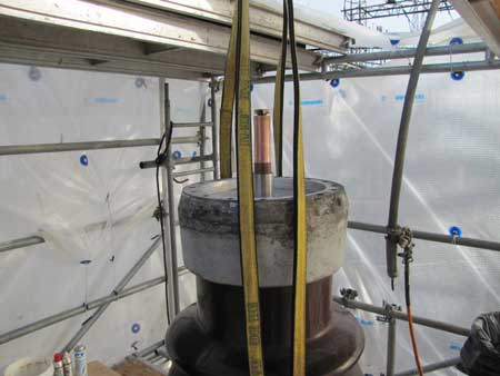
The following are the steps involved to replace the insulator on a 230kV pipe type cable.
1. All of the insulation (rubber and compound) must be removed from the single conductor stainless steel pipe
2. Once the single conductor goes underground, it goes to a trifurcating cable splice, and then the three conductors are in one pipe
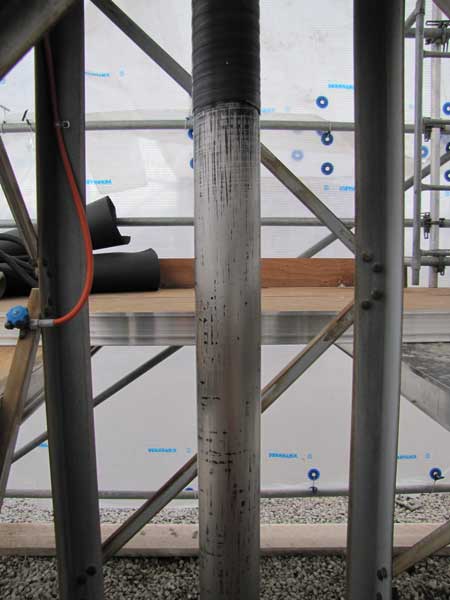
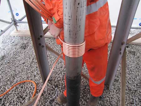
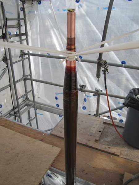
3. With the pipe exposed the jointer starts wrapping the the copper tube
4. Continue to wrap, leaving a space in the middle and then duplicate the first section of wrap
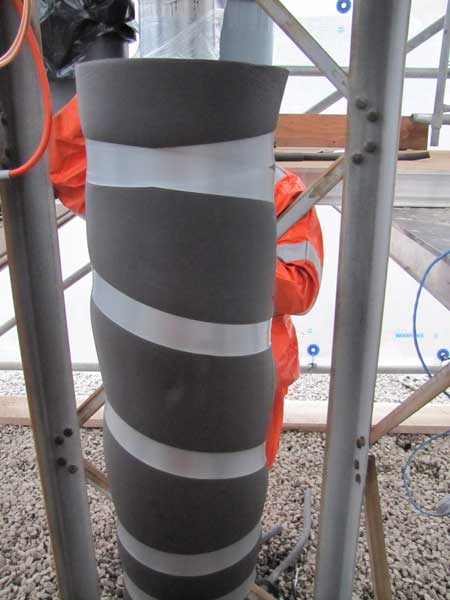
5. Once all the tubing is applied, thermocouple probes are placed at the middle and both “outside” points of the freeze to monitor temperature, and a moisture barrier is applied
6. Heavy duty pipe insulation is installed (several layers)
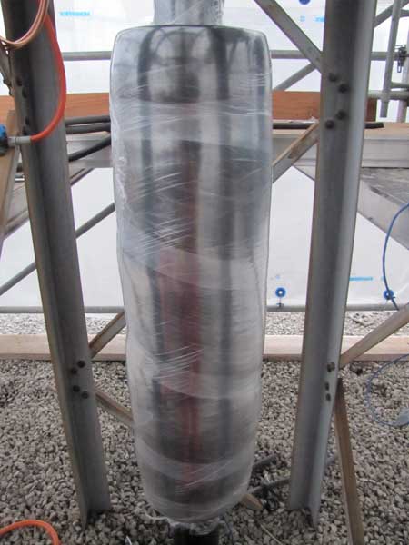
7.With the wrap completely installed, another moisture barrier is applied
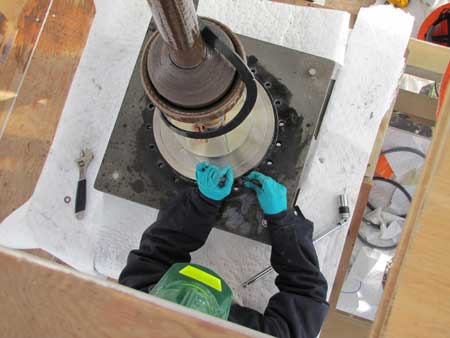
8.Before the freeze can be initiated, the oil pressure must be greatly reduced, to just above ‘static’ pressure, or the constant force of the oil would prevent the cable from freezing
9.Depending on pipe size, conductor size, length of pipe, time of year, once the liquid nitrogen is applied, it takes various amounts of time to freeze any particular cable. All three thermocouples are constantly monitored
10. With the desired temperature reached, the freeze plug is active. The termination (pothead) is drained, and the old insulator is removed
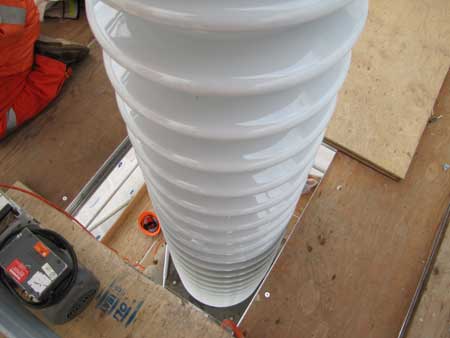
11.The cable termination is meticulously inspected and cleaned. Flushed several times with hot cable oil
12.The new porcelain is installed
13. Once the new glass is bolted back on to the cable and sealed, the Liquid Nitrogen can be shut down, and the cable begins to thaw
14. Once cable has thawed the cable termination (pothead) is slowly filled with cable oil, under vacuum
THORNE & DERRICK
Thorne & Derrick are national distributors of LV, MV & HV Cable Installation, Jointing, Substation & Electrical Equipment – servicing businesses involved in cabling, jointing, substation, earthing, overhead line and electrical construction at LV, 11kV, 33kV, 66kV and EHV. Supplying a complete range of power cable accessories to support the installation and maintenance of low/medium and high voltage voltage power systems:
uploaded by Chris Dodds - Thorne & Derrick Sales | Marketing Manager
All Images Courtesy Of: Douglas Page (Instructor & Cable Splicer at Hydro One Training and Development Services).
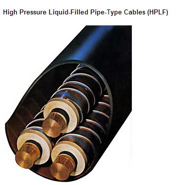
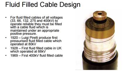
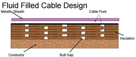
Fluid Filled Cables
Fluid filled high voltage cables have been used for over 80 years with some circuits installed in the 1930’s still operating successfully today without any deterioration.
The fluid contained within a fluid filled cable has to be kept at a positive pressure under all conditions of loading and ambient temperature change.
Fluid filled cables rely on the presence of pressurised cable fluid to work efficiently – if the circuit suffers an oil leak the cable network is compromised.
The pressure used depends on a number of factors:
Voltage and size of cable
The length of the cable
The route the cable follows
Whether the cable has a leak
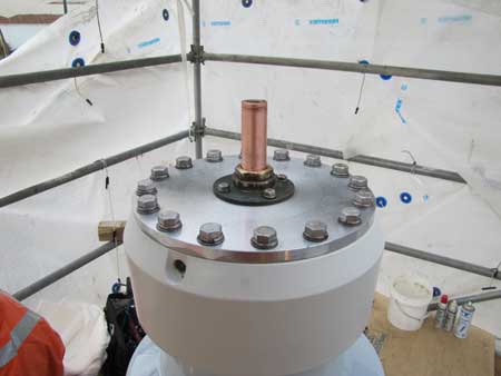
High Voltage Cables
The fluid forms an integral part of the high voltage cable insulation and prevents the formation of voids in the lapped papers around the conductor – also the cable fluid aids the conduction of heat away from the conductor allowing the cable to be run efficiently than a cable without it.
The following photo sequence shows how to find a single drip of oil in approximately 12km of Single Core LPOF PILC 115KV direct buried cable.
LPOF Low Pressure Oil Filled
PILC Paper Insulated Lead Covered
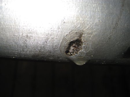
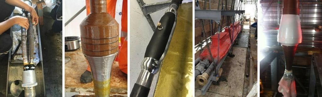
1. Cathodic lead erosion is clearly visible on the EHV power cable – this is usually caused by ground factors such as gas mains, neighbouring cable circuits, water mains etc. The aged underground EHV cable is suffering natural degradation and overtime a deterioration in the cables normal cathodic protection has caused service issues with the cable circuit – the cable becomes the sacrificial anode and starts to break down.
2. Cable type : Transmission & Distribution Voltage – 115kV LPOF PILC Single Core.
3. LPOF EHV cables are monitored by gauges and pressurized by pre-pressurized tanks with internal baffles, that expand and contract with the cable, maintaining a constant pressure. If the pressure cannot be maintained, an alarm is triggered.
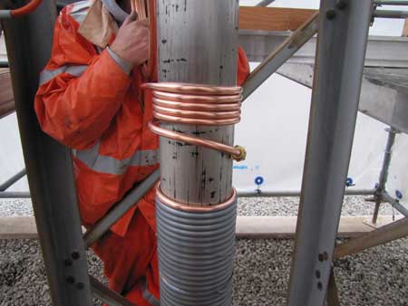
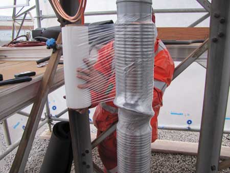
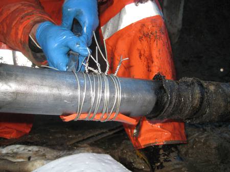
4.To find the oil leak in 10, 15, 20, or 100km of cable, it all starts the same way. Find the approximate centre of the cable circuit, excavate safely and install a cable freeze.
5. Very similar to a pipe type freeze, the coil must be installed on the bare lead.
6.
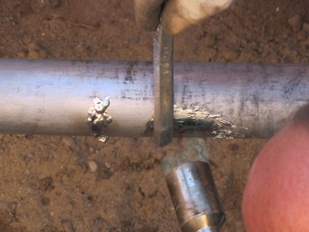
7. Along with a freeze, to monitor the temperature, the EHV jointer/splicer must install thermocouple temperature monitors which consist of two conductors of dissimilar metals that react to the temperature change differently allowing the monitors to display the actual temperature.
8.
9.
10.Once the freeze has been initiated, the gauges are monitored, the side that loses pressure, is flagged and deemed the side that requires further attention
11. Freeze pit – once the leak has been narrowed to 50-100m length, the final excavation begins. Until signs of leaking cable oil are found
13.After a lengthy search, this is what you are looking for, although opinions vary, constant drip can yield various amounts of accumulation. Some say it could fill a bathtub in 72 hours
14. Once located a temporary EHV cabl repair is made, while environmental remediation is done
15. “Tinning” of the cable repair, so the lead will adhere to the cable
16.The EHV cable repair is complete – after this the jointer must solder a copper lead connected to a sacrificial “anode” that erodes before the cable
Thorne & Derrick are national distributors of LV, MV & HV Cable Installation, Jointing, Substation & Electrical Equipment – servicing businesses involved in cabling, jointing, substation, earthing, overhead line and electrical construction at LV, 11kV, 33kV, 66kV and EHV. Supplying a complete range of power cable accessories to support the installation and maintenance of low/medium and high voltage voltage power systems:
Andrew Linley, Compliance Director at Electrical Safety UK Limited
The following article about the need to carry out an Arc Flash Study has been produced by Andrew Linley, Compliance Director at Electrical Safety UK Limited. Special thanks for the permission to re-publish your article.
Andrew has vast experience in electrical installation, maintenance and the requirements and thepracticalities of electrical inspection, testing and certification. At Electrical Safety UK Limited, they provide expert consultancy and advice for organisations across Europe concerned with the safe management of risk associated with all electrical work activities.
Is arc flash study a legal requirement?
The simple answer is yes…
An arc flash study needs to be carried out by an electrical safety expert, to determine hazards and risks in electrical systems. The need to carry out a suitable and sufficient risk assessment, and to put measures in place to protect those who could be put at risk, is mandated by the following regulations:
Regulation 4(1) – the Electricity at Work Regulations 1989
Regulation 3(1) – the Management of Health and Safety at Work Regulations 1999
Regulations
Regulation 4(1) of the Electricity at Work Regulations 1989 states ‘All systems shall at all times be of such construction as to prevent, so far as is reasonably practicable, danger’.
Regulation 2(1) of the same regulations defines danger as meaning the risk of injury and ‘injury means the death or personal injury from electric shock, electric burn, electrical explosion or arcing, or from fire or explosion initiated by electrical energy, where any such death or injury is associated with the generation, provision, transmission, transformation, rectification, conversion, conduction, distribution, control, storage, measurement or use of electrical energy’.
Electricity poses arc flash hazards, and the risks posed are electric shock, burns, fires, arcing and explosion.
We demonstrate the need for Arc Flash Study and Arc Flash Protection
Regulation 3(1) of the Management of Health and Safety at Work Regulations 1999 states ‘every employer shall make suitable and sufficient assessment of (a) the risks to the health and safety of his employees to which they are exposed whilst they are at work; and (b) the risks to the health and safety of persons not in his employment arising out of or in connection with the conduct by him of his undertaking, for the purpose of identifying the measures he needs to take to comply with the requirements of and prohibitions imposed upon him by or under the relevant statutory provisions and by Part II of the Fire Precautions (Workplace) Regulations 1997’.
Conducting arc flash studies
It has been established that we need to conduct arc flash studies of the workplace to determine risks and hazards, but how exactly are they conducted?
The on-site evaluation results in fault current and coordination analysis, fault equipment labelling, recommendations for improvements and requirements for PPE (Personal Protective Equipment). An arc flash study can be carried out by several organisations, including Electrical Safety Uk Ltd.
Electrical Safety Management is our core business. We provide expert consultancy and advice for blue chip organisations across Europe concerned with the safe management of risk associated with all electrical work activities. ESUK provide a multi-faceted holistic approach including a full electrical safety management program, project management and policy documentation all bespoke to the client’s requirements including fully accredited and bespoke training courses and personnel assessment programmes.
Here at Electrical Safety UK, our team delivers a range of professional services to customers in a variety of market sectors. The team prides itself on the quality of the services it delivers to companies at the heart of manufacturing, engineering, energy, food production and education in the UK and Europe.
1 Electrical Safety Management – Specialist consultancy and advice concerned with the safe management of risk associated with all electrical work activities. ESUK offer a multi-faceted approach including a full electrical safety management program, full project management and policy documentation bespoke to a client’s requirements.
2 Electrical System Studies – ESUK is the UK’s foremost exponent of Arc Flash Technology and carry out a wide range of power system studies, including Fault Level Analysis to IEC and ANSI standards, Protection Coordination, and complex Arc Flash Risk Assessments.
3 Training – ESUK offer both accredited and bespoke training courses including City & Guilds, IOSH, Safety Pass Alliance, Energy and Utility Skills. ESUK are also registered with the EEIAS and CIPD for recognition and accreditation of bespoke training courses.
Thorne & Derrick are national distributors of LV, MV & HV Cable Installation, Jointing, Substation & Electrical Equipment – servicing businesses involved in cabling, jointing, substation, earthing, overhead line and electrical construction at LV, 11kV, 33kV, 66kV and EHV. Supplying a complete range of power cable accessories to support the installation and maintenance of low/medium and high voltage power systems:
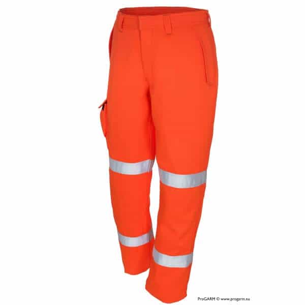
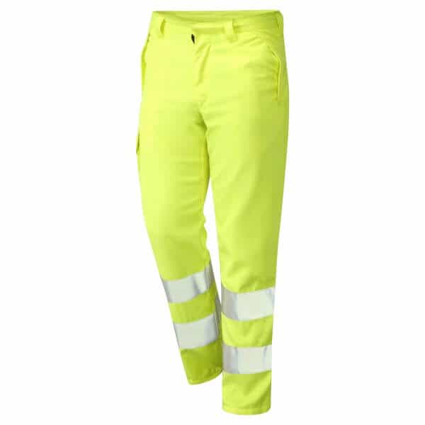
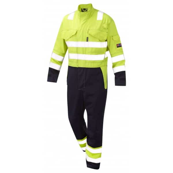
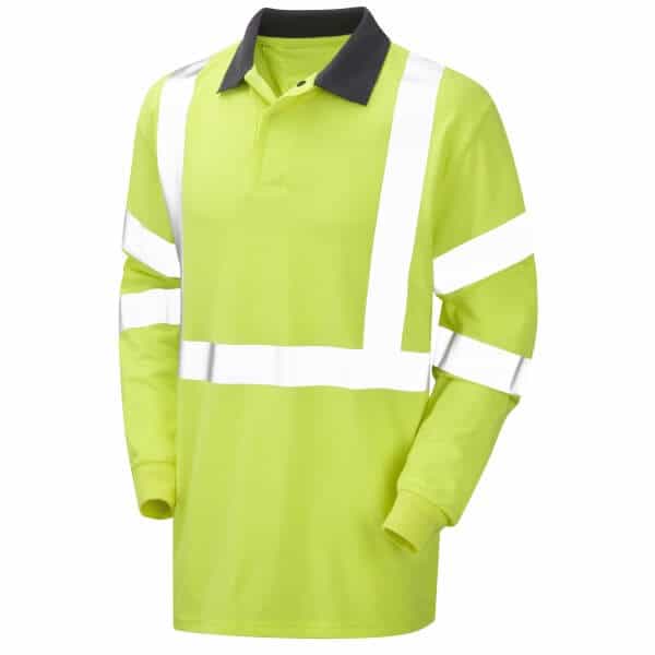
Thorne and Derrick are proud to be distributors of ProGARM arc flash coveralls and protection.
We can help – should you require arc flash calculators or advice on the type of clothing and protection available please do not hesitate to contact us.
klauke ekm60unv – universal cutting, crimping & punching tool The Klauke EKM 60 UNV is a versatile battery powered hydraulic universal tool engineered that can be used as a battery powered cable crimping tool and battery operated cable cutting tools that comes...
INDUSTRIAL LABEL PRINTING SOLUTIONS When clear, durable and professional identification is required across control panels, cable systems, production facilities and industrial installations, print quality, reliability and ease of use are critical. Cembre industrial label printers are designed to support...


")