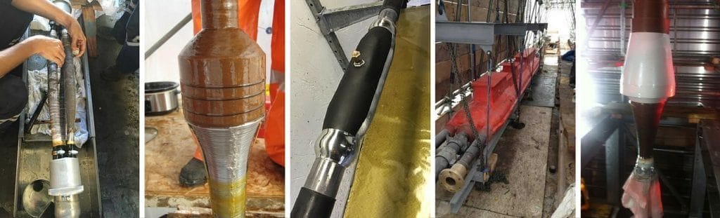
Polymeric insulated cables distributing high voltage electricity at 33kV can be used to joint cables with XLPE or EPR type insulation, armoured/unarmoured and with copper wire screen (BS7870) or copper tape screened cables (BS6622).
Heat shrink cable joints feature integrated stress control sleeves and torque controlled mechanical shearbolt connectors can be used to connect conductors (copper or aluminium) without resort to use of crimping tools or associated die sets.
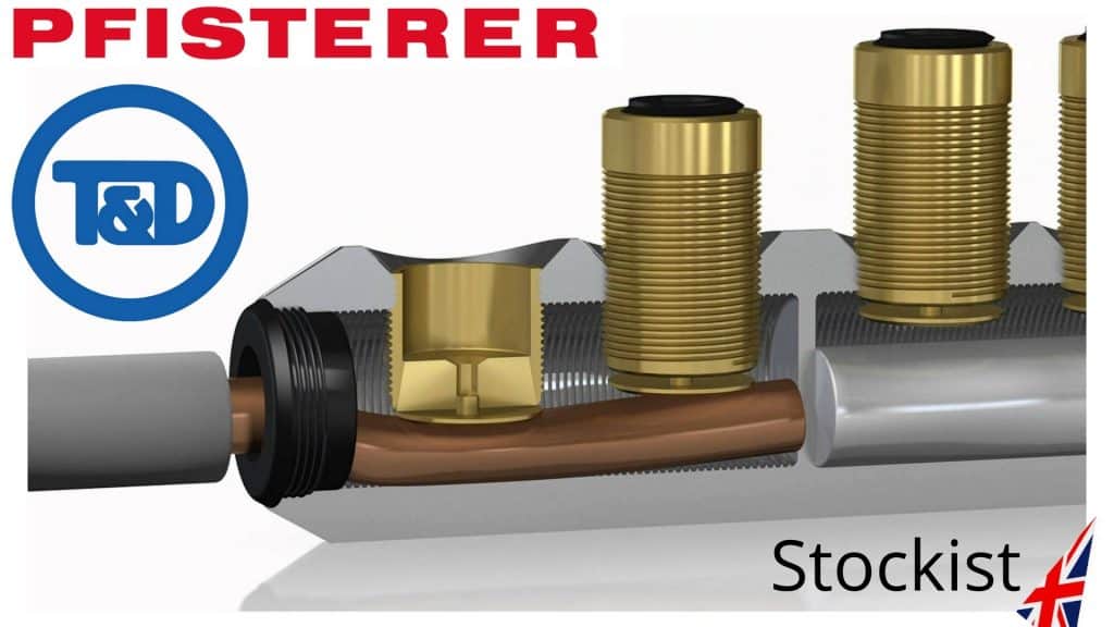
Mechanical cable connectors are ideal for confined space cable jointing where there is restricted working space in manholes, cable vaults and underground trenches, especially on large cross sectional area conductors where hydraulic crimping heads coupled with foot pumps are required for conductor jointing. Bolted cable connections, such as Pfisterer SICON connectors, are installed directly onto the 33kV conductor using standard Allen keys. The bolt shears off smoothly and cleanly when tightened by the cable jointer.
Pfisterer Sicon – cable lugs and connectors with stepless shearbolts for use with cable joints and terminations on high voltage power cable systems
Heat Shrink
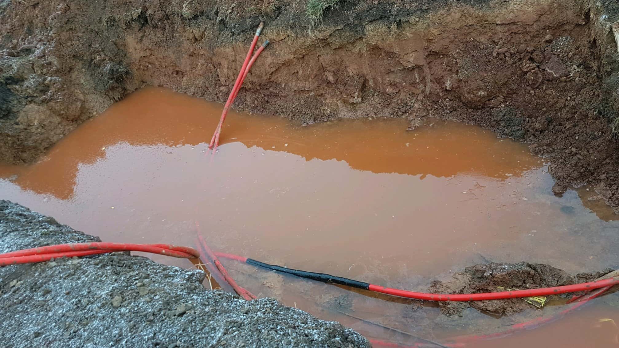
Primarily, a heat shrink cable joint provides electrical insulation, mechanical protection and stress control for high voltage power cables – integral also to the cable joint design is the requirement to prevent water ingress into the cables. Although initial risk assessments would include consideration of electrical water damage, such as cable flood damage, the requirement to deliver medium/high voltage power can necessitate cable exposure to potential flooding, condensation and water immersion. A robust cable joint is designed to withstand the deteriorative effects of water in both indoor or outdoor environments.
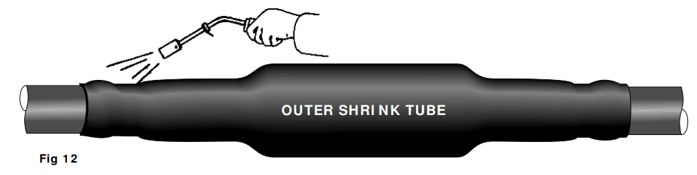
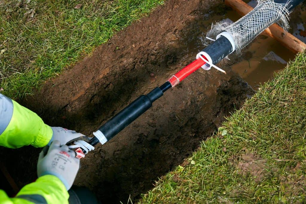
The cable joint kits include thick-wall heat shrink adhesive lined tubes to provide high performance water sealing, protection and corrosion resistance in above ground exposed or direct buried underground cable trenches – the outer protection heat shrink tubing (colour black) provides a moisture barrier to water ingress through the activation of an inner lining of adhesive which melts and flows upon the application of a heat source provided by the cable jointers gas torch.
Prior to installing the outer shrink tube the jointer should clean, de-grease and abrade the outer cable sheath of the 33kV cable – to achieve an even wall thickness the cable jointer should keep the flame moving and avoid scorch or burn damage to the heat shrink or cable.
The jointer will apply heat evenly to the centre of the cable joint – once the heat shrink tube is fully recovered (“shrunk”) the joint should be smooth, wrinkle-free and the heat activated sealant should be visible at the tube ends in contact with the cable sheath.
The tough and durable heat shrink provides reinstatement of cable sheath or jacket insulation and withstands trench backfill prior to energisation of the HV joint.
The 33kV joints are installed using normal procedures for heat shrink cable joints with clear installation instructions confirming precise cable stripping dimensions and marking measurements for sheath, semicon and insulation removal – joints are installed using the standard cable jointing tools depending upon cable construction.
Although not designed to be permanently submerged in water, 33kV cable joints use heat shrink tubes to prevent water ingress into high voltage cables whether buried underground or located onto cable containment in MV-HV substations.
Should you require any assistance with the selection or specification of MV-HV joints or terminations please do not hesitate to contact us.
The following Training Video shows the installation process for installing heat shrink joints to single core 33kV cable – this Video is for familiarisation purposes and not intended as a substitute for attending recognised industry training courses and achieving manufacturers competency. The Video produced by SPS with narration provides comprehensive guidance from the initial stripping and removal of the 33kV cable sheath to the final completion of the heat shrink joint.
T&D distribute the most extensive range of LV, MV & HV Cable Jointing, Terminating, Installation & Cable Pulling Equipment – we service UK and international clients working on underground cables, overhead lines, substation earthing and electrical construction at LV, 11kV, 33kV and EHV transmission and distribution voltages.
The following LinkedIn Comments provide some expert guidance, insight and advice on how to avoid the dangers of substandard installation of heat shrink cable terminations on high voltage systems. Generally, when categorising voltages we include 11kV and 33kV power systems into the high voltage (HV) definition.
However contractors, manufacturers and the industry would also argue that 11/33kV should be classified as medium voltage (MV) and HV commences at 66kV.
The Comments below were in response to the following site installation photograph of an 11kV cable termination. Let us know your thoughts and we will include to the thread in order to improve readers knowledge and reduce industry risk.
Scott Wilkie HV Power Distribution Engineer at Scottish Power – cable entry points through the cable gland plate would be better if centralised. Crossing cores with increased stress over insulation, clearly used to phase out the cable sections in the box. Would prefer to see 11kV single cores with a trifurcating joint outside of the cable box if that was possible.
Brendan Preece, P.E.HV Electrical Engineer – in addition to previous comment, use a high voltage two-hole compression lug that matches the two-hole terminal pad for good low-resistance metal-to-metal surface area contact.
Tony Haggis Director at Tony Haggis Consulting Ltd– the HV cable box is designed for single core cable terminations only. It’s impossible to use 3 core cable and maintain clearances between the cores – hence the black discharge marks. Not sure why anyone would use 3 core XLPE cable these days – single core triplex is cheaper and much easier to joint and terminate. Most UK DNOs and European utilities use it. There is no way to recover the heat shrink cable terminations other than cut all the cables out and replace with single cores with trifurcating joints outside. Also I’m amused by the use of the outdoor rainsheds – not only unnecessary but they also make the clearances worse.
Colin WoodmanTeam Leader & HV Cable Jointer DELPRO –I could be wrong but looking at it I am struggling to see where, other than down near the bottom of the heat shrink cable terminations, that the semi con screen had been cut and the mastic installed…cables must only cross where the semi con is still in tact. This is why HV cable terminations like this should be designed from the top down not from the cable strip up.
Tony Haggis Director at Tony Haggis Consulting Ltd – in view of Colin Woodman’s comment I’ve looked a bit closer at the picture and it could be salvaged by remaking the heat shrink termination using what we used to call a “crossed core” kit that we used to use with 11kV belted paper cable. This kit included heat shrink semicon heat shrink tubes that we used to screen the cores up to the stress control tube which was placed up near the cable lug.
Perhaps stripping off the existing cable termination and extending the core screen with semicon tubes could then place the stress control tubes up between the perspex phase barriers. I personally wouldn’t guarantee it as we don’t know what discharge damage has already been caused. If one was determined to use 3 core 11kV cable in this box then a top down screen off measurement would work but I would want the termination manufacturer’s view first. Looks like the semicon has been terminated taking a measurement from the crutch leaving unscreened core in the areas to be crossed.
I’ve always advocated taking the screen-off measurement from the HV cable lug thus leaving maximum screened core in the box. However, most termination manufacturers give a bottom up dimension but will give a top down dimension when asked.
Michael White CEO at Campbell White – Colin you are spot on where a cross or a roll on end termination you must know creepage distance on these lineal stress terminations: on all Raychem terminations 90mm from top of black semiconductor heat shrink to open conductor then you can roll and cross on the semicon screen and have no trouble. There is no science taught these days on stresses and zero potential for cable jointers. I can understand third world jointers making mistakes but not educated ones.
Dan James MIETTechnical Services Engineer – Senior Authorised Person at NG Bailey – complete mess. As suggested above this can’t be saved. Cut it all back, do a cable joint to single cores, get rid of them heat shrink sheds and perspex.
Richard PoulterSPS Managing Director – looks like a 33kV termination because of the phase barriers but more so the sheds per phase and the length of the stress control tubes which you can see the outline of below the anti-track tubes (they look about 260mm long). You can make out the semi-conductive screen ends because of the small bulge where the yellow stress tape is applied but most of the stress control tubes are fitted below this point rather than above it. So the majority of the stress tube is not doing anything.
I suspect the heat shrink cable terminations are fitted this low because the cable jointer was probably trying to achieve a distance of 250mm from the top of the stress tubes to the bottom of the lug barrels. The cable end termination box just does not look big enough for this voltage class termination, probably better to have used single core cable and they might have had a chance of achieving the cable spacings. Lots of discharge going on. That phase on the right looks like totally different anti-track but the intense heat has discoloured the other phases by the looks of things. Has it blown yet?
Maybe do a Trif joint below the cable box and take single cores in. If little space, use Raychem IXSU heat shrink kits or a cold shrink termination. Life expectancy is hard to pinpoint but there is a lot of discharge going on so they should schedule this within a week otherwise the damage will be a lot more. The temperature at the discharge can be as high as 1000 degC and once the carbon deposit increases on the cores, the quicker it will fail.
Andy O’MalleyAllteck IBEW 258 EHV Cable Jointer/Splicer– they could have broke this 3 core cable into single cores outside of the 11kV box utilising jacket reintroduction kits and glanded the single cores individually and this would of been a perfect installation.
John ThompsonHigh Voltage Cable Splicer– Okay, honestly it looks like hell. But let’s pick this apart. There are 12 cables in this picture (4 per phase). The 11kV terminations appear to be in some kind of a protected cabinet so they could operate for a length of time if this was some form of a temporary hookup. In my opinion this is more of an engineering catastrophe than a cable splicers mishap.
Joe KinnaneHV Electrician/ Transmission Cable Jointer With Western Power–they clearly needed to be “broke out” way lower than they have been with longer spaces between the stress point on the different phases! Heat shrink tubes weren’t pushed down fully on the breakout either.
Evan Paul GalleozzieApproved Electrician –bad design of the entry of the 11kV cables which has resulted in a mess of the cable terminations. And a few of the the cables look in a poor condition. And the CPC’s could have been installed properly using crimping tools, too much copper showing. Bad, bad, bad.
Christopher WilliamsHead of Services and Support at IPEC Ltd – looks like a severe case of surface tracking on the heat shrink cable terminations (a form of partial discharge). This is likely caused by the inadequate installation of the feeder cables increasing the electrical stress across the surface of the high voltage cable insulation. Any dirt/dust/contamination would then have helped create small electrical discharges across the insulation causing the carbonisation you see in the image. Over time this will compromise the insulation further, finally resulting in a catastrophic failure. Interestingly, this could have been detected via PD monitoring, in this case, ultrasonic emission would have been emitted and sensors could have detected the inception and location of this defect long before it got to this stage!!!
Thorne & Derrick
Suppliers of HV Joints, Terminations & Connectors
Thorne & Derrick distribute the most extensive range of MV HV Medium & High Voltage Cable Joints, Terminations & Connectors from manufacturers including 3M, Prysmian, Nexans Euromold, Elastimold, Pfisterer CONNEX and Shrink Polymer Systems.
Heat shrink, cold shrink, push-on and slip-over cable accessories enable the jointing, terminating and connection of 11kV-33kV and 66kV-132kV cables to oil, air or gas insulated switchgear, transformers, motors and overhead lines distributing electricity at MV HV.
Thorne & Derrick stock 11kV 33kV 66kV Joints & Terminations suitable for XLPE, PILC and EPR cables, in both heat shrink and Cold Shrink technologies, to service the medium/high voltage power cable accessory requirements of UK and international customers.
Stockists & Distributors of High Voltage Joints Terminations Connectors
Contributed By:Watkins and Jacomb Construction Power & Consultancy
WJCPC are specialist LV HV Cable Termination & Jointing contractors with over 20 years experience in the High Voltage Electrical Industry covering the utilities, renewable energy, rail, data centre and general industry sectors – UKPN competent for LV & HV Termination and Jointing Of Cables, Confined Spaces, Substation Entry and Cable Fault Finding.
In the following post Ben Jacomb highlights 5 serious shortcomings across cable terminations installations on the same site – this installation investigation underlines the scope for jointer error at various key stages including critical cable preparation mistakes prior to installing the HV cable terminations.
Clearly under-trained, unskilled labour has been used to perform work normally carried out by highly-skilled, experienced and certified cable jointers.
This article covers the termination of BS6622 11kV 3 Core XLPE high voltage power cables – in a previous contribution WJCPC discussed and displayed the process of terminating 11kV Triplex cables.
Steel Wire Armour – poor termination of the 11kV wire amours (SWA)
Semicon Screen – failure to observe correct measurement and use correct jointing tools
XLPE Insulation – undue care and attention by jointer when working on 11kV insulation
Disregard Of Cable Termination Instruction – failed to apply the void filler correctly
Cable Stripping – insufficient cable insulation on 11kV cable due to overstripping
“On behalf of one of our clients we were asked to complete several heat shrink terminations onto high voltage 11kV 3 core XLPE SWA power cables. After the first inspection of the HV cable terminations I was not satisfied with the cable jointers technique undertaken to remove the semi conductive layer, which had been done by using a semicon cable stripping tool. The high voltage semi conductive layer is semi bonded type so the stripping of the layer should be stripped by using a depth knife and the ringing of the stress control point on the 11kV cable by a soft file.
Thorne & Derrick are the UK’s largest stockist of cable jointing tools manufactured by Alroc.
Any marks left in the XLPE insulation of the 11kV cable will influence the magnetic fields inside the power cable and should be removed by emery cloth to leave a smooth finish eliminating any voids. If the heat shrink tube is shrunk on top of a void there will be moisture and where there is moisture there will be arcing, burning and then potential failure of the 11kV cable. If the semi conductive layer is not removed correctly at the crucial point then discharges arise causing damage to the cable.
♦ Further Reading:The Semicon Screen – A Most Critical Point In Any MV Cable Joint, Termination Or Connector.
Perfect Semicon Screen Cutback
Below are pictures and comments on several findings from recent 11kV cable termination inspections.
Steel Wire Armour
When terminating 11kV cables with heat shrink cable terminations there is a requirement to ensure safe earthing and termination of the armour wires (SWA steel wire armour) using cable glands, commonly referred to as “top-hat” cable glands.
In most 11kV cable installations the cable gland body can be installed after completion of the 11kV terminations. Completion of the final 11kV connections should be done before bolting the cable gland into place on the 11kV cable box.
Note, the correct jointing procedure for termination of the wire armour is to open-up or splay the SWA armours and bend back over onto the cable gland body and using worm drive clamps to connect the armour and screen earth braids to the gland body.
Before applying heat with a gas torch to the heat shrink tube, which is used to shroud and provide environmental and corrosion protection to HV cable terminations, the jointer can abrade the cable sheath and then using cable cleaning tissues thoroughly degrease the 11kV cable.
Insulated 11kV cable glands are also available for industrial medium/high voltage power systems with steel wire (SWA) or aluminium wire (AWA) cables.
Incorrect Installation Of HV 11kV Cable Glands
Correct Installation Of HV 11kV Cable Glands
Semicon Screen
The semi conductive layer cut back should be 20mm and not over according to the HV cable terminations instruction – on this cable installation the dimensional error was consistent on all 5 cable termination breakdowns with semicon screen layers averaging between 25mm – 40mm.
Semi Conductive Layer Length
Here, the semi conductive layer has been left on the 11kV XLPE insulation which can cause surface tracking and eventual flash over. This occurred on 2 out 5 cable termination breakdowns.
Semi Conductive Layer Left On The Cable Insulation
XLPE Insulation
Damage To 11kV Cable Insulation
Disregard Of Cable Termination Instruction
Here, the yellow mastic void filler has not been applied correctly by the cable jointer. It clearly states in the heat shrink termination kit instructions that 5mm of yellow mastic is to be installed on the copper tape screen and to continue over the semicon layer and then finish 10mm onto the cable installation. The yellow mastic is used to fill voids – the mastic provides stress relief from electrical fields so it is essential this is installed correctly.
Yellow Mastic Void Filler Not Applied Correctly On The Cable Terminations
Score marks on insulation – this will more then certainly cause flash overs as previously mentioned in this report.
Score Marks On 11kV Cable Insulation
Cable Stripping
The image above shows the XLPE cable insulation cut for a cable lug on one cable termination – the required insulation measurement is 5mm.
On all the cables that have been stripped using a stripping tool the cable jointer has left less then the minimum requirement of insulation needed around the conductor of the 11kV cable. The cable manufacturer has confirmed that the finished XLPE insulation around a conductor should be 3.4mm and any part of the insulation under the minimum of 2.95mm is a failure.
After breaking down 5 cable terminations to find 5 different failures on each one this is very concerning. I would not energise any of the 11kV cable terminations until further investigation.”
HV Cable Terminations
Thorne & Derrick distribute the most extensive range of HV Cable Terminations & Joints to suit 11kV/33kV medium and high voltage power cables, including indoor cold shrink and heat shrink terminations, outdoor pole-mounted terminations or separable connectors for gas insulated equipment applications.
HV High Voltage Cable Joints | Cable Terminations | Cable Connectors | MV HV 11kV 33kV
Joint | Terminate | Connect Medium & High Voltage Cables MV HV
THORNE & DERRICK are national distributors of Cable Installation, Jointing, Substation & Electrical Safety Equipment MV HV – we service UK and global businesses involved in cable installations, cable jointing, substation, overhead line and electrical construction at LV, 11kV, 33kV and EHV.
Contact us for 3M Electrical, ABB, Alroc, AN Wallis, CATU Electrical, Cembre, Centriforce, CMP, CSD, Elastimold, Ellis Patents, Emtelle, Euromold, Filoform , Furse, Lucy Electric & Zodion, Nexans, Pfisterer, Polypipe, Prysmian, Roxtec, Sicame, WT Henley.
Invitation
Thorne & Derrick invite you to join LinkedIn’s largest LV-HV Electrical Discussion Group : Low & High Voltage Power, Cabling, Jointing & Electricals.
Discussion subjects include cable installations, cable jointing, substation, overhead line and electrical construction at LV, 11kV, 33kV and EHV. Network, engage and promote your profile, company or products with over 10,000 influencers.
How Can T&D Help?
T&D’s marketing team can help generate new business leads and opportunities by targeting organic search terms and ensuring your brand/product is providing lead generating organic ranks on Google for specific keywords.
Unbranded open spec inquiries could be coming your way with our dedicated SEO campaigns that are supported by our digital marketing strategy.
All pages can be tracked extensively via Google Analytics so you can see exactly how many clicks a specific search term is receiving. Working together we can tailor a plan which best suits your needs.
In a nutshell
What T&D Can Do For You?
Ensuring your product range/brand is well optimised via targeted keywords on our websites
Blogs campaigns (including guest blogs) help to support the overall keyword purpose
Opportunity to gain Google Snippets increasing click through rates
Improve your organic ranks for search terms of your choice
Real time analysis and detailed data capture from Google Analytics
Increase web traffic with anchor text links back to your website
Examples of T&D SEO Strategy
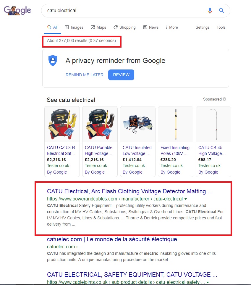
T&D are able to dominate the top results on Google for specific keyword search terms:
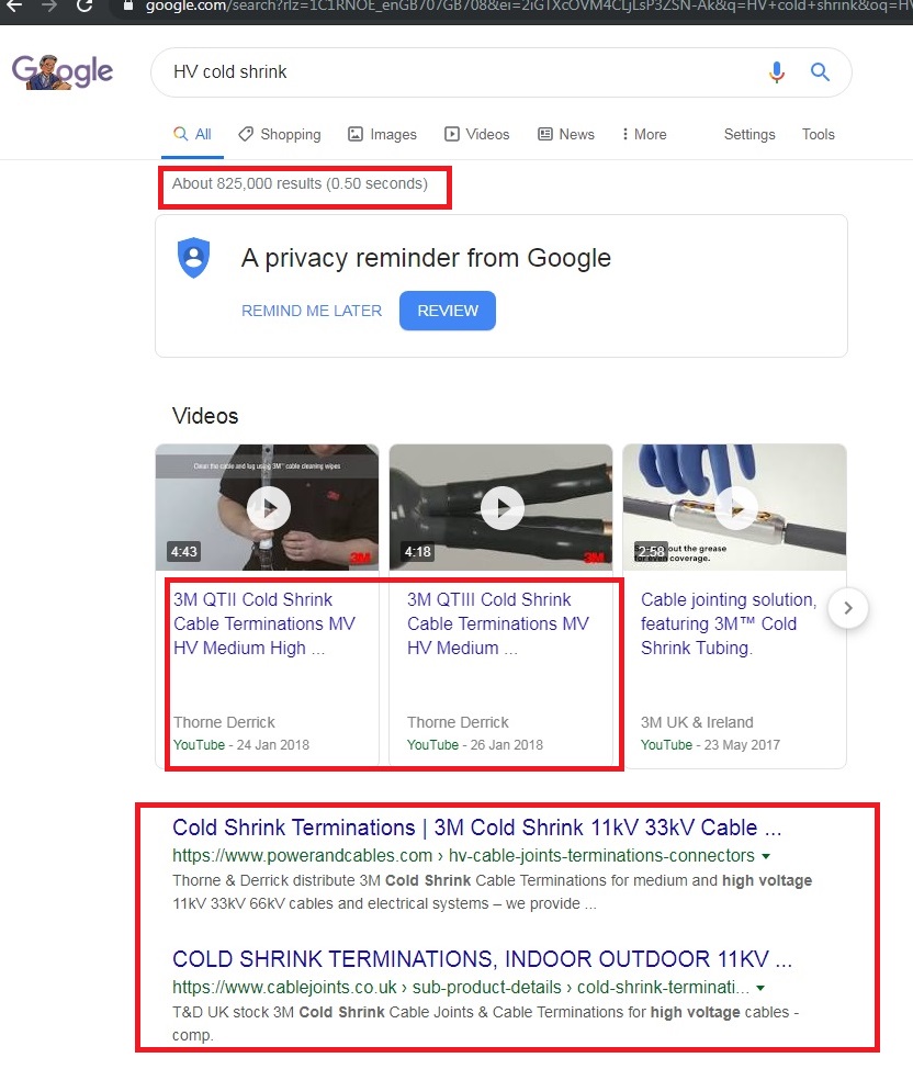
Below shows T&D organically ranking 1st and 2nd on Google and also occupying the top 2 positions for YouTube videos.
Or T&D can drive traffic to your supplier page on our website:
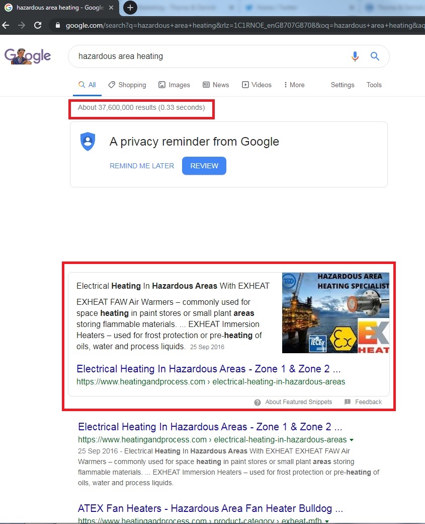
Featured Snippets are another important Google development that can help drive more traffic to a certain webpage for a specific search term:
Not only to we get featured snippets for products and brands but also key industry based search terms:
T&D can provide detailed analysis of targeted keywords and show web traffic curves via Google Analytics. Below shows the Google Analytics Curve for www.powerandcables.com since launch and the record number of visitors on the website at one time.
uploaded by Chris Dodds - Thorne & Derrick Sales & Marketing Manager
Cold Shrink Tubes
Thorne & Derrick International, based in the UK, are the largest stockist and supplier of Cold Shrink Tubes manufactured by 3M Electrical – contact us for competitive prices, stock availability and delivery to UK and overseas destinations.
This video by 3M Electrical shows how to apply Cold Shrink Tubes safely and correctly.
3M Cold Shrink Tubes are a series of open-ended, tubular rubber sleeves, which are factory expanded and assembled onto a removable core. They are supplied for field installation in a pre-stretched condition and used by electrical engineers, installers and cable jointers to carry out electrical cable insulation, cable sheath repair and splice joints on cable containment or cable trench applications.
The 3M video shows how to install the cold shrink tubes by unwinding the removable core allowing the tube to shrink and form a tight waterproof seal to prevent water or humidity ingress into the cable. Quicker, easier and with enhanced installer safety benefits compared to heat shrink tube alternatives without a requirement for a heat source or tooling.
Cold Shrinking – the installer should use a gentle unwinding motion to release the expanded Cold Shrink tube from the core maintaining a consistent and even technique resisting temptation to snatch and pull as this will snag the plastic tail within the cold shrink tube. The outer core should remain relatively stationary while unwinding the inner core – the live memory action of the specially formulated 3M Cold Shrink material ensures a permanent, durable environmental seal and insulation. The tough, durable, EPDM rubber construction ensures 3M Cold Shrink tubes withstand operating temperatures of -40 to 194 degrees F (-40 to 90 degrees C).
Black EPDM Cold Shrink Tubing Manufactured by 3M Electrical
Hazardous Areas
Consequently, cold shrink tubes have been adopted by the hazardous area industries (oil, gas and petrochem) for safe cable sealing and environmental protection in potentially explosive atmospheres and confined spaces where flammable gases or combustible vapours combined with “hot-working” could ignite the “Fire Triangle”.
Suitable for hazardous area cable repair, however where installation location is exposed hydro carbons a complete range of ATEX cable joints are available for jointing cables in hazardous areas, Zone 1 and Zone 2.
Safe Cable Protection & Jointing In Hazardous Areas & Potentially Explosive Atmospheres – cold shrink is safe to use where “hot-working” is precluded
The absence of a naked flame requirement eliminates fire risk and removes the danger of incurring heat, burn or scorch damage to cable sheath by over-heating with gas torches.
The core is removed manually by a simple clockwise unwinding of a tail piece of the inner former – after the cold applied tube has been positioned for installation over an inline connection, cable terminal lug or other similar application the cold shrink is collapsed to form an effective cable seal.
Faster to install for use on LV, MV or HV cables where working access is possible to an open cable end either by cable cutting or disconnecting from supply point.
Other possible applications include electrical installation, cable repair, mechanical protection and moisture sealing barrier – providing a constant radial seal and pressure even under thermal cyclical load.
No playing with fire when installing Cold Shrink by 3M
Selecting Cold Shrink Tubes
Cold shrink tubes are supplied in a range of sizes with specified minimum/maximum tolerances per tube – the selection of the correct 3M tube requires the outside diameter of the cable to ideally be midway between the recommended min/max range of the shrink tube. Once installed the tubes are immediately energisable and suitable for direct burial, overhead or submersed applications on 1000 volt cables located in indoor/outdoor locations in both safe (non-hazardous) and hazardous area cable locations.
Cold shrink tubes are available in EPDM and Silicone.
Cold Shrink – invented by 3M over 40 years ago and now the preferred technology for heat-free jointing, terminating, sealing and abandonment of LV HV cables
We hope you find this video informative and educational, contact T&D for technical support, quotations and stock availability for 3M Cold Shrink Tubes.
Silicone Cold Shrink – Fire resistant & Low Smoke Zero Halogen
Silicone cold shrink tubes are open ended, silicone rubber, tubular sleeves installed onto cables, pipes and umbilicals to provide a watertight seal with additional resistance for fire, acids, ultra violet light, moisture and flame – the cold shrink tube is inherently low smoke zero halogen (LSOH).
No heat source or naked flames are required to install cold shrink – specified for cable joint, repair or cable splice work in hazardous area locations or potentially explosive atmospheres.
The 3M 8440 series of silicone tubes are outlined in the below table to enable correct selection – call should you require any assistance.
The silicone cold shrink tubes manufactured by 3M Electrical provide primary electrical insulation on solid dielectric (rubber EPR and plastic XLPE) insulated low voltage LV cables up to 1000 volts.
➡ Visit 3M Electrical for further information about 3M cable joints, terminations, tapes and insulation to seal, repair, splice and connect LV MV HV cables.
Celebrating Charlie & Ella’s Level 4 Sales Executive Apprenticeships At Thorne & Derrick International, we are proud to champion talent development and recognise the dedication required to achieve professional growth. We are therefore delighted to congratulate Charlie Baines and...
Thorne & Derrick will be Exhibiting at Solar & Storage Live UK 2026 at the NEC Birmingham from 22nd–24th September, showcasing our support for HV Cable Accessories, Joints, Terminations, Separable Connectors, Cable Tooling and Grid Connection Products used across...



























Evan Paul Galleozzie Approved Electrician – bad design of the entry of the 11kV cables which has resulted in a mess of the cable terminations. And a few of the the cables look in a poor condition. And the CPC’s could have been installed properly using crimping tools, too much copper showing. Bad, bad, bad.
Christopher Williams Head of Services and Support at IPEC Ltd – looks like a severe case of surface tracking on the heat shrink cable terminations (a form of partial discharge). This is likely caused by the inadequate installation of the feeder cables increasing the electrical stress across the surface of the high voltage cable insulation. Any dirt/dust/contamination would then have helped create small electrical discharges across the insulation causing the carbonisation you see in the image. Over time this will compromise the insulation further, finally resulting in a catastrophic failure. Interestingly, this could have been detected via PD monitoring, in this case, ultrasonic emission would have been emitted and sensors could have detected the inception and location of this defect long before it got to this stage!!!
Thorne & Derrick
Suppliers of HV Joints, Terminations & Connectors
Thorne & Derrick distribute the most extensive range of MV HV Medium & High Voltage Cable Joints, Terminations & Connectors from manufacturers including 3M, Prysmian, Nexans Euromold, Elastimold, Pfisterer CONNEX and Shrink Polymer Systems.
Heat shrink, cold shrink, push-on and slip-over cable accessories enable the jointing, terminating and connection of 11kV-33kV and 66kV-132kV cables to oil, air or gas insulated switchgear, transformers, motors and overhead lines distributing electricity at MV HV.
Thorne & Derrick stock 11kV 33kV 66kV Joints & Terminations suitable for XLPE, PILC and EPR cables, in both heat shrink and Cold Shrink technologies, to service the medium/high voltage power cable accessory requirements of UK and international customers.
Stockists & Distributors of High Voltage Joints Terminations Connectors