

Blog
IEC 61482-2 | Arc Flash Protective Clothing Standards
September 15th, 2020
IEC 61482-2 | Arc Flash Protective Clothing Standards
Arc Flash Protection
IEC 61482-2 Arc Flash Standard
ProGARM produces safety garments that protect workers against the Thermals Hazards of an Electric Arc. Each arc flash protective garment is carefully designed by ProGarm to offer the maximum protection to the new arc flash standard IEC 61482 whilst ensuring comfort and outstanding durability.
As Arc Flash clothing items come under the requirements of Category 3 Protective Clothing, these garments are manufactured under Module D Quality Control Procedures.
WHAT IS AN ELECTRIC ARC?
Electric Arc and the arc flash created is the light and heat produced as part of an arc fault; a type of electrical explosion or discharge that results from a low impedance connection through air to ground or another voltage phase in an electrical system.
The intense heat can create temperatures as high as 19,000°C and it also produces electric shock, force and large quantities of thermal radiant energy.
What is the Risk?
In any situation where your employees are working with electricity, an Arc Flash can occur and as such the maximum energy of default circuits in any electrical installation must be able to be determined. The risks of an electric arc exposure are:
- Electrocution – potentially fatal
- Extremely high levels of Radiant Heat
- 1st, 2nd or 3rd Degree burns – 3rd Degree burns cause permanent damage
IEC 61482-2:2018 PERFORMANCE & DESIGN REQUIREMENTS
Performance requirements for materials and design requirements for garments, plus Marking and User Information.
This part of IEC 61482 is applicable to protective clothing used in work if there is an electric Arc hazard. This standard specifies requirements and test methods applicable to materials and garments for protective clothing worn by electrical workers to protect them against the thermal hazards of electric Arc based on relevant general properties of the textiles, tested with selected textile test methods, and one of the Test Methods as defined below.
IEC 61482-1-1:2019 ‘OPEN ARC’ TEST METHOD
‘Open Arc’ test method (ATPV test and garment test). This replaces IEC 61482-1:2002. The ‘Open Arc’ test method is the same as the original North American method for measuring the Arc Thermal Performance Value (ATPV), as used in ASTM F1959. Materials or assemblies are given an ATPV/EBT/ELIM value, expressed in kilojoules per square metre (kJ/m2), which can be converted into the familiar cal/cm2.
Or
IEC 61482-1-2:2007 ‘BOX ARC’ TEST METHOD
‘Box Arc’ test method (Fabric classification and garment test). The ‘Box Arc’ test method is based on the original European method described in ENV 50354, with a heat transfer measurement. Materials or assemblies are classified as Arc Protection Class (APC) 1 (4 kA) or APC 2 (7kA).
During this test, a fabric sample is exposed to an electric Arc produced by a 4kA or 7kA short circuit. In the test, the Arc does not last any longer than 500ms. The amount of heat transmitted through the sample is measured during and after the test. On the basis of the resulting data and a Stoll curve, the length of time it would take to cause the onset of second-degree burns is subsequently determined. Samples are also assessed for after-flaming, hole formation, melting, etc.
GARMENT TESTING & FABRIC TESTING
It is important to note that not only the fabric should be tested for conformance to the Arc Flash Standard, but also the complete garment or garment assembly itself.
The garment test is not testing for energetic value but is testing to ensure that the garment structure remains intact after the Arc exposure and that components such as zippers and buttons are still functional and do not contribute further injury to the wearer by melting or heat transfer.

ProGARM | Functional Arc Flash Clothing, Protection & PPE For Everyday Wear
As a result of this ProGARM have written a short guide to the new IEC 61482-2:2018 standard to highlight the key bits of information you need to be aware of when reviewing your PPE specification and the key terminology that you need to understand.
Choosing the right PPE for your team can be difficult and with all the standards to consider it can feel quite overwhelming. This guide aims to help people make a more informed decision about what PPE is best for you.
You can download the PDF guide via this link or see the attached pdf below.

IEC 61482-2 2018 Free Guide

Arc Flash Clothing | Polo Shirts | Jackets | Coveralls | Trousers | Sweatshirts | Helmets
We can help – should you require arc flash calculators or advice on the type of clothing and protection available please do not hesitate to contact us.
Further Reading
- IEC 61482-2 2018 – Get Up To Speed With The New Arc Flash Standard
- Arc Flash Clothing – PPE To Protect Highways, Street Lighting & Utility Contractors
- Arc Gloves | New Arc Flash Dexterity Gloves from Protection Specialists ProGARM
- New Arc Flash Coveralls from Protection Specialists ProGARM
Arc Flash Learning & Resources

Thorne and Derrick are proud to be distributors of ProGARM arc flash coveralls and protection.
We can help – should you require arc flash calculators or advice on the type of clothing and protection available please do not hesitate to contact us.


THORNE & DERRICK
Thorne & Derrick are national distributors of LV, MV & HV Cable Installation, Jointing, Substation & Electrical Equipment – servicing businesses involved in cabling, jointing, substation, earthing, overhead line and electrical construction at LV, 11kV, 33kV, 66kV and EHV. Supplying a complete range of power cable accessories to support the installation and maintenance of low/medium and high voltage power systems:
- Slip-on Cable Terminations
- Cold-shrink Cable Terminations
- Heat-shrink Cable Terminations
- Cable Joints – Heat & Cold-shrink
- Separable Connectors (Euromold)
- Surge Arresters & Switchgear/Transformer Bushings
Key Product Categories: Duct Seals | Cable Cleats | Cable Glands | Electrical Safety | Arc Flash Protection | Cable Jointing Tools | Cable Pulling | Earthing | Feeder Pillars | Cable Joints LV | Joints & Terminations MV
Cable Jacket Repair | 3M Electrical Webinar
September 14th, 2020
Learn more about Cable Jacket Repair by signing up to the webinar
Damage to the Cable Jacket & Sheath is a fairly common issue on site.
A cable might be endangered even before deployment: for example, a cable may have been dragged across a concrete floor and snagged. When the Cable Sheath is damaged, the electrical system may become compromised from moisture and contaminants. Even the smallest scratches can be dangerous as they can be deeper than they appear and increase when bending the cable. This is why Cable Jacket Repair methods are paramount.
cable jacket RepaiR
With 3M

Cable Jacket Repair with 3M Electrical Tapes
- 3M Electrical tapes are the robust and convenient solution to repair cable jacket damages in the field.
- Tape fits all cable sizes—no need to keep the big range of materials on stock—just a couple of rolls in your toolbox.
- Repair with tapes doesn’t need fire or heating. It’s convenient for work in confined spaces, and in most cases, it’s a durable and economically efficient solution. 3M electrical tapes can be used for both temporary and permanent repair.
cable Sheath & Cable JAcket Repair RECOMMENDATIONS
The nature and type of damage to a cable determines which selection of tapes and methods of repair should be used. The tapes may be used to repair scratched or slightly damaged cable jackets, or more substantial repairs; where a section of the cable jacket is missing. Where the conductor or inner parts of a cable’s construction is not damaged, the repair of the cable jacket is possible with the use of 3M tapes. Otherwise, if these parts are damaged, the cable would have to be either spliced or replaced.
3M Tapes for Cable Jacket Repair
In the following circumstances, methods of Cable Jacket repair from 3M, including 3M Scotch Electrical Tapes, can be used
- For PVC and Rubber cables, low and medium voltage
- For single- or multi-conductor cables
- For damages which don’t penetrate to conductor depth
Cable JAcket & Sheath Repair Methods
The different levels of cable damage are demonstrated below: with the suggested repair methods for each.
 |
 |
 |
| Damage Level 1 | Damage Level 2 | Damage Level 3 |
| Minor damages. Surface damages like scratches and grooves from sharp edges. | More substantial damages with cable cores intact. Cuts and breakouts of the cable jacket. | A new cable splice is required. Severe damages with damages cable cores. Punctures and deep damages affecting the inner layers of the cable. Further detection of the cable is necessary. |
3M Electrical tapes for cable jacket repair
Rubber Mastic tapes, manufactured by 3M, are the main components of cable jacket repair solutions. These flexible tapes go on smoothly and bond instantly to make electrical repairs in the field an easy task. A mastic adhesive securely adheres to most power cable jacket materials without loosening or separating, delivering a reliable seal that will maintain the integrity of the cable jacket in the long term.
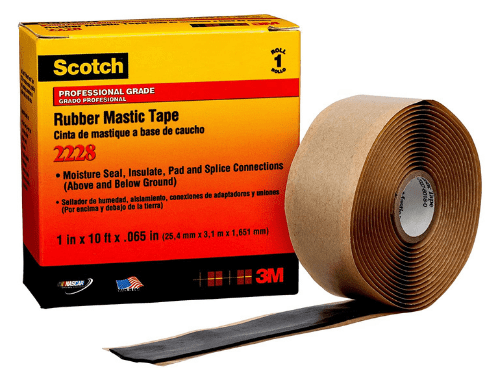


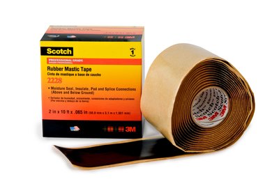
3M SCOTCH 2228 RUBBER MASTIC TAPE
- 3M Scotch 2228 Tape is highly conformable and super stretchy in all weather applications.
- resists UV rays, abrasion, corrosion, alkalies and acids.
- Primary insulation for splices up to 600V.
- Max Temperature: 90°C / 194°F emergency overload of 130°C / 266°F
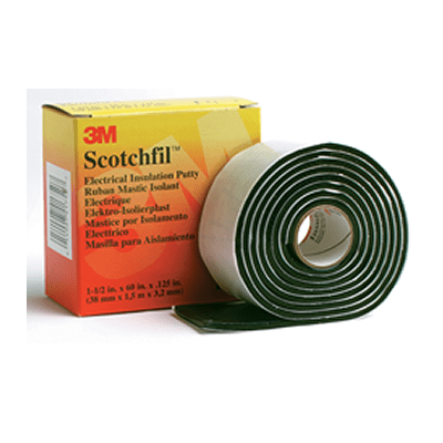
3M SCOTCHFIL ELECTRICAL PUTTY
- 3M Scotchfil Electrical Putty is a self-fusing, insulating putty in tape form.
- Electrical insulation putties can be applied to the deep holes to seal and shape the surface and exclude water ingress.
- Smooths over irregular shapes and pads sharp edges.
- Max Temperature: 80°C / 176°F
3M SCOTCH SUPER 33+ VINYL ELECTRICAL TAPE
- Premium Vinyl tapes add mechanical protection and radial pressure to the repaired area.
- 3M Scotch 33+ Tape is highly conformable and super stretchy in all weather applications
- Resists UV rays, abrasion, corrosion, alkalies and acids.
- Max Temperature: 105°C 221°F
- Can be applied in cold environments down to -180C and is rated to operate in temperatures from 105° C to -40°C.
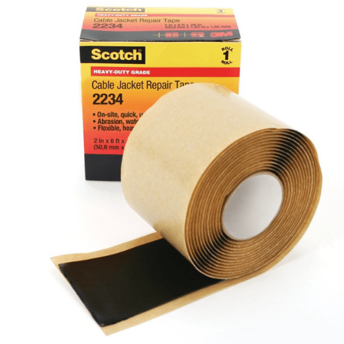
3M SCOTCH 2234 CABLE REPAIR TAPE
- 3M Scotch 2234 Tape is designed specifically to repair damages on the cable jackets.
- The outer layer of this tape is composed of vulcanised CSM rubber to provide outstanding resistance to abrasion, chemicals, tearing, and cut-through.
- Max Temperature: 105°C / 221°F
Alternative solutions for minor damage repairs
Besides Scotch® Cable Jacket Repair Tape 2234, 3M provides alternative tapes solutions for Cable Jacket repairs with different characteristics. See the table below with the different options.
| 1 | 1. Wrap Scotch® Rubber Mastic Tape 2228 over the scratch. | 2. Then overwrap with Scotch® Super 33+™ Vinyl Electrical Tape over the whole repair length for the mechanical strength. | Scotch® 2228 is softer then Scotch® 2234, it’s not flame retardant and has lower chemical resistance vs. Scotch® 2234. |
| 2 | 1. Wrap Scotch® Rubber Mastic Tape 2228 over the scratch. | 2. Scotch® Heavy Duty Vinyl Electrical Tape 22 over the whole repair length for the mechanical strength. | Scotch® 22 is more robust and thicker than Scotch® Super 33+™, but it’s less abrasion resistant than Scotch® 2234. |
| 3 | 1. Scotch® Mining Tape 31 over the whole repair length. | Very similar characteristics to Scotch® 2234, but even more hard. It was specially designed for the Mining industry. |
Alternative solutions for substantial damage repairs
Similar to the repair of minor damages, there are alternative solutions to Scotch 2234 tape for substantial damage repairs.

Cable Jacket Repair
Further Reading
- MV Cable Jointing & Some Jointers Tips Using 3M Scotch Tapes
-
3M Scotchcast Cable Splicing & Jointing Kits Supplied For Marine & Offshore Cables
LV, MV & HV Jointing, Earthing, Substation & Electrical Eqpt
Thorne & Derrick International are specialist distributors of LV, MV & HV Cable Installation, Jointing, Duct Sealing, Substation & Electrical Equipment – servicing UK and global businesses involved in cable installations, cable jointing, substation, overhead line and electrical construction at LV, 11kV, 33kV and EHV.
THORNE & DERRICK Product Categories: Duct Seals | Cable Cleats | Cable Glands | Electrical Safety | Arc Flash Protection | Cable Jointing Tools | Cable Pulling | Earthing | Feeder Pillars | Cable Joints LV | Joints & Terminations MV HV
Viscas 69kV Straight Joint
September 11th, 20203 Legends of Splicing
Wong Kuaising
Patrick O’Malley
Andy O’Malley
R.E.S.P.E.C.T
Wise Wong levitating like a shaman Jointer watchful over O’Malley Snr & Jnr feeling the fire burning and adrenalin rushing through their veins like current through cable.
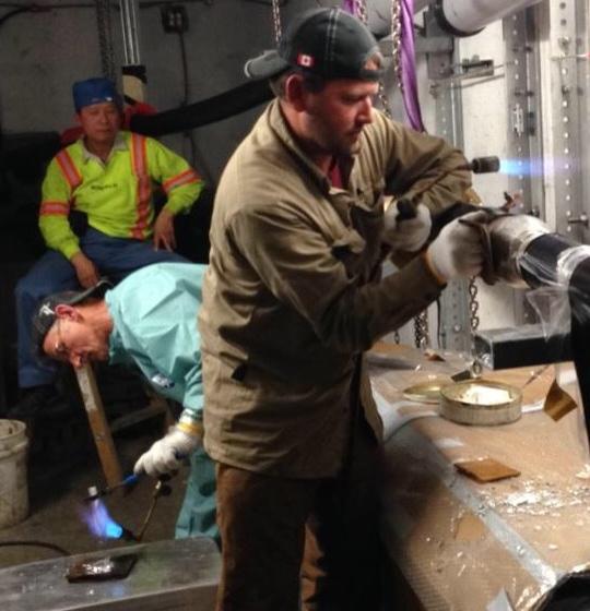
Viscas 69kV Straight Joint
Further Reading
- MANWEB – Cable Jointing Past & Present by Patrick & Andy O’Malley
- Lead Cable Jointing – Where Craftsmanship Becomes Artistry
- Confined Spaces Cable Jointing Using 3M Cold Shrink Straight Joint Splice (25kV)
![]()
Jointers blog
Subscribe now to our POWER NEWSLETTER– a monthly email circulation packed with news, projects, videos, technical tips, training information, promotions, webinars, career opportunities and white papers.
Includes access to our popular JOINTERS BLOG with contributions from utility professionals, linesmen and cable jointers working on MV HV EHV cables and overhead lines typically at 11kV, 33kV, 66kV and up to 132kV.
15,000+ Subscribers. ➡ 
25kV Live Line Voltage Indicators | Network Rail Approved
September 10th, 2020
25kV Live Line Voltage Indicators
Network Rail | PADS Approved | PADS Number 0091/012337
Thorne & Derrick distribute a wide range of PB Weir Substation Earthing and Transmission Line Earthing Equipment: including line end clamps, earth end clamps, portable earthing leads and operating poles for high voltage substations.
The Network Rail Approved C31 Live Line Indicator is designed for use upon overhead a.c. rail electrification systems operating at 25kV nominal voltage to indicate the presence of extra high voltages to aid safe working practices.
C31 Live Line Voltage Indicator Kit Includes
|
 C31 Live Line Indicator Kit | Network Rail Approved |
Voltage Indicator PRODUCT FEATURES
|
The 25kV Live Line Indicator incorporates a number of important safety features, including Dual Independent Circuitry. This means that the analogue meter and the LED indicators work completely independent of each other. If one circuit fails, the other will keep on working for your safety.
An Automatic ‘Meter Prover’ operates every time the tester is turned on, proving the electrical and mechanical operation of the analogue meter.
Triple Resistor Sets ensure that the remaining resistors are sufficient to safely protect the operator and the equipment, in the unlikely event of one HV resistor failing.
The resistors are tested at 40 KV AC.
The 50sqmm Aluflex grounding cable will safely conduct the full force of the OHL system in the event of a catastrophic failure of the equipment, such as direct contact with the overhead line.
Automated Test Cert Validation, warning lights flash when test certificate has expired.
 The C31 Live Line Voltage Indicator kit comprises the following:
- the live line indicator, which comes in a tough protective carry case
- a high voltage probe and hook – shrouded for use in wet weather
- an 8 metre length of 50mm2 aluflex cable with a rail clamp.
- battery charger for charging the C31’s internal Nickel Metal Hydroxide batteries.
Range |
0-40kV ac
|
LED change over |
11kV ± 500V
|
Test duration |
<25kV 10 mins > 25kV 1 min
|
Absolute Max. Rating |
40kV ac
|
Accuracy |
Analogue 2%
|
Analogue Op. Temp |
-40c to +70c
|
LED Op. Temp |
-10c to +50c
|
Seal Rating
|
Tester body IP65, Probe and gauge IP68
|
Further technical details:
- For use upon overhead a.c rail electrification systems at 30kV nominal voltage.
- 12kV +/- 5% Threshold voltage. Compatible with standard Westminster operating poles and Primary Insulator pole.

Rail Cable Accessories, Electrification
& Installation Equipment
Thorne & Derrick supply an extensive range of 400V-33kV Rail Cable Accessories & Power Distribution Sytems including feeder pillars to contractors undertaking Low Voltage Power Distribution, HV Electrification & Substations, DC Traction & Networks, OLE and Track Feeder Cable Renewals – a complete range of Network Rail PADS approved track terminations, cable joints, cable repair and connection products up to 25kV, including 3M Cold Shrink, Pfisterer CONNEX and Nexans Euromold products.
Full range of Cable Pulling Equipment & Products to ensure safe and efficient of rail cables in to cable ducts and containment infrastructure including cable troughs.

Removal of Semi-Conducting Screens (Polymeric Cables)
September 7th, 2020
Cable Jointing Tools
Semi-Conducting Screens
STANDARD TECHNIQUE: CA2C/9
Relating to General Requirements for 11kV Cable Jointing
Extract from a Western Power Distribution Company Directive
The below guide explains the best way for the removal of semi-conducting screens.
Before commencing the level of PPE required for this operation shall be as the matrix given in General Requirement 3, your attention is drawn to the Use of Solvents General Requirement 1.
25.1 General
There are two types semi-conducting screens used on polymeric cables, fully bonded and easi-strip.
Virtually all polymeric cables used within WPD South have the easi-strip semiconducting screen.
While WPD Midlands have large amounts of easi-strip and fully bonded semi-conducting screens.
The method described here is for the removal of the easy-strip semi-conducting screen, which requires basic but effective cable jointer tooling and relative ease of removal to the installer.
Cable manufacturers currently supply two types of semi-conducting screen; both manufacturing methods can produce either easi-strip or fully bonded. With easi-strip semiconducting the material it’s important to have a compound such as ethylene vinyl acetate (EVA) which is strippable from the insulation.
In order for strippable screens to have sufficient tear strength during the removal from the insulation, it is necessary for the thickness to be approximately 1mm but the screen thickness can be thinner for harder materials. There are no such constraints with bonded screens and because the semiconducting materials are very expensive, thickness is kept to a minimum, 0.5mm being a typical figure.
The manufacturing methods are described as: –
- Monasil – identified by its smooth appearance.
- CCV (Continuous Catenary Vulcanising) – identified by its heavily ribbed appearance and characteristic acetophenone odour
- VCV (Vertical Catenary Vulcanising) – identified by its heavily ribbed appearance and characteristic acetophenone odour
25.2 Easi-strip Semi-conducting Screens
Note: – The method described below shall be THE ONLY APPROVED METHOD ADOPTED FOR USE within WPD for the removal of the easi-strip semi-conducting screens.
This phase of the jointing procedure must be undertaken with utmost care throughout this operation, failure to do so can be the cause or be a contributory factor in the failure of the joint or termination.
Cleanliness and attention to detail are vital, it is essential to avoid damaging the insulation at the semi-conducting screen termination, and any cuts or voids etc. will lead to the premature failure of the MV cable joint or termination.
2.1 Method of Removal
Refer to Drawing GR3D 6.25.1 whilst undertaking this General Requirement.
2.1.1 Mark the semi-conducting screen at its termination point with a white Chinagraph pencil.
2.1.2 Using PVC tape, apply (sticky side outermost for one complete turn) around the circumference of the cable at its termination point apply sufficient turns to provide a straight and square edge to guide the Abra file – Fig 1.
2.1.3 Using the Abra file with medium pressure, file evenly around the semi-conducting screen until the conductor insulation just shows – Fig 2.
Note: – The insulation must be seen continuously around the cable otherwise the semi-conducting screen may be lifted below its cable termination point.
2.1.4 Use a mirror to check the underside of the cable; there should be a smooth neat chamfer on what will be the remaining circumferential edge.
Note: – Where raggedness of the termination appears, run the Abra file with light pressure to remove high points; take care not to damage the insulation.
Ribbing of the semi-conducting screen may be removed by gently warming with a gas torch until the semi-conducting screen achieves a smooth surface.
2.1.5 Using the correct depth guarded knife (0.4mm for Prysmian 33kV & 0.6mm for Tratos 33kV cables) and starting just above the circumferential termination point make longitudinal scores spaced approximately 120° along the core length to its end – Fig 3.
Note: – Depending on cable size the three longitudinal scores may be reduced, two being the minimum otherwise undue stress is applied to the installers hands and cable.
Where there is extreme difficulty of drawing the depth guarded knife from the circumferential termination point to the cable end, and providing a cable tie is placed around the circumferential termination point to protect the shown insulation, the cable may be scored from the open end towards the circumferential termination point.
Utmost care must be given if using this alternative method, damage at the semiconducting screen termination point will result in failure.
2.1.6 Lift the semi-conducting screen at the open cable end and peel back the strips to completely remove – Fig 4.
2.1.7 Using aluminium oxide tape abrade the exposed insulation ensuring a smooth finish along its length and at the semi-conducting chamfer (any ribbing within the surface of the insulation must be abraded out to a smooth finish).
Note: – 400 grit is normally sufficient to provide this finish, but a start with 320 grit and finishing with 400 grit may be required.
2.1.8 Using an approved cable cleaner degreaser and white wipes, remove all traces of the semiconducting screen wiping from the cable end towards the termination point.
Note: – After each run change the wipe otherwise contact with semi-conducting material will come into contact with the insulation leaving possible tracking traces.
2.1.9 Finally remove the PVC tape applied in 2 and thoroughly check the insulation along its complete length ensuring its contamination free – Fig 5.

Removal of Semi-Conducting Screens (Polymeric Cables)
25.3 Fully Bonded Screens
This phase of the jointing procedure must be undertaken with utmost care throughout this operation, failure to do so can be the cause or be a contributory factor in the failure of the joint or termination.
Cleanliness and attention to detail are vital, it is essential to avoid damaging the insulation at the semi-conducting screen termination, and any cuts or voids etc. will lead to the premature failure of the joint or termination.
Note: – The stripping tool, Alroc CWB 18-60, which has been supplied to all the WPD Jointers on the 33kV Conversion course is designed for bonded screen cables ONLY and shall NOT BE USED on any EPR or XLPE EASI-STRIP CABLES.

Alroc CWB 18-60 Tool – Bonded Semiconductor Stripper | LV MV HV 11kV 33kV 66kV 132kV EHV Cable Jointing Tools
The bonded semi-con stripping tool issued to Midlands Jointers by Central Networks SHALL NOT be used on the 33kV system.
3.1 Method of Removal
Refer to Drawing GR3D 6.25.2 whilst undertaking this General Requirement.
The Alroc/Pfisterer tool works across the range of diameters over the semi-con screen of 18mm to 60mm.
Note: – THIS TOOL DOES NOT REQUIRE ANY SILICON GREASE TO OPERATE IN ADDITION THIS IS THE ONLY TOOL TO BE USED FOR BONDED SEMI-CON REMOVAL.
3.1.1 Ensure the cable is clean and straight.
3.1.2 Mark the semi-conducting screen at its termination point with a white Chinagraph pencil.
3.1.3 Set the tool stop to the required distance. Apply a roll spring to the white Chinagraph mark.
3.1.4 Close up the tool up using the large, red plastic knob, to provide a firm grip that will still allow the tool to rotate, as shown in GR3D 6.25.2.
3.1.5 Position the cutter at the front edge of the screen and set the depth of cut using the small metal knob as shown in GR3D 6.25.3. The adjustment is anticlockwise to increase the depth of cut, clockwise to decrease. If necessary, practice on a scrap piece of cable to obtain the correct depth setting. The ideal setup will have two thirds of the removed material to be the black semi-con and one third of the removed material being the translucent XLPE insulation.
3.1.6 With the correct depth set, now rotate the whole tool using the rear handle, in the direction of the arrow that is printed onto the body of the toool – as the tool is rotated it will move progressively down the cable, peeling the screen. Do not apply excess pressure. The selected depth setting should produce a clean, smooth cut free of black semi-conducting material.
3.1.7 When the required screen termination position is reached, the tool stop will come in contact with the roll spring thus providing clean screen edge and prevent the tool from moving down the cable. Continue to rotate the tool until a clean cut screen edge is produced. Open the tool and remove the tool on completion.
3.1.8 After the tool is removed, examine the surface of the insulation to ensure all semiconducting layer has been removed.
3.1.9 Using aluminium oxide tape, abrade the exposed insulation ensuring a smooth finish along its length and at the semi-conducting chamfer (any ribbing within the surface of the insulation must be abraded out to a smooth finish).
Note: – 400 grit is normally sufficient to provide this finish, but a start with 320 grit and finishing with 400 grit may be required.
3.1.10 Using the approved De-Solvit 1000FD degreaser and white wipes, remove all traces of the semi-conducting screen wiping from the cable end towards the termination point.
![]()
Jointers blog
Subscribe now to our POWER NEWSLETTER– a monthly email circulation packed with news, projects, videos, technical tips, training information, promotions, webinars, career opportunities and white papers.
Includes access to our popular JOINTERS BLOG with contributions from utility professionals, linesmen and cable jointers working on MV HV EHV cables and overhead lines typically at 11kV, 33kV, 66kV and up to 132kV.
15,000+ Subscribers. ➡
