

Blog
Cable Laying & Cable Sleeve Installation | Guidelines by Draka Communications
January 14th, 2020-
uploaded by Chris Dodds - Thorne & Derrick Sales | Marketing Manager

Cable Laying & Cable Sleeve Installation

Draka Communications – part of Draka Holding N.V. situated in Amsterdam – offers a variety of reliable products in copper and fibre optic technology for data transmission and telecommunication.
They have long-term experience and knowledge in the cable and fibre business ensuring their major market position today. Draka Communications can be found in more than 32 countries in Europe, Asia, North and South America.
This series of Blogs focuses on the importance of the correct cable laying, cable pulling and cable sleeve installation and how to avoid damages and faults.
The below Articles will give you some guidance in the laying and installation of outdoor LV MV HV cables.
It is important to note that accuracy during preparation of run, laying of cable and installation of sleeve is crucial as your little additional work is worth it to avoid the cost what may arise in the case of a complaint. It is recommended to choose products from recognised manufacturers and that you have the best conditions for a proper installation.
The below articles containing laying and installation instructions are correct to the best of our knowledge and have resulted from consideration of current and recognised techniques and technologies. They are intended as instructions for the correct laying and installation of outdoor cables.
- Cable Laying | The Importance of Cable Installation Instructions
- Cable Drums | Recommended Transport & Storage
- How to Prepare Cables To Avoid Cable Damages & Faults
- Cable Pulling | Safe Pulling of Cables Using Motorised Pullers
- Cable Pulling | Safe Pulling of Cables Using Manual Laying
- Installation of Cable Sleeves | Jointing & Splicing Cables
- Installation of Rail Foot Cables
Cable Pulling Equipment
Thorne & Derrick distribute an extensive range of Cable Pulling & Laying Equipment to enable the safe installation of fibre and copper cables within the telecommunications industry. Safely installed cables reduces operational and maintenance requirements to the network and reduced service interruption to telecom cables, wires, ducts, cabinets and exchanges – products include cable spiking tools, conduit rods, cable lubricant, cable socks and rollers.

Medium Voltage Cable Accessories – Best Practice Guide
January 12th, 2020-
uploaded by Chris Dodds - Thorne & Derrick Sales | Marketing Manager

Europacable represents the largest cable manufacturers in the world, as well as highly specialised small and medium sized businesses from across Europe.

Medium Voltage Cable Accessories
This series of Blogs have been written by MV Cable Accessory Manufacturers to help promote ‘best practice’ in the installation of their products including joints, terminations and connectors for medium voltage power cable systems.
It is principally for MV cable installers but hopefully will be instructive for all involved in the construction and operation of medium voltage (MV) cable networks. Cable networks cannot be built without jointing cables together and terminating them to substation electrical equipment (switchgear/transformers) or overhead lines.
The long-term reliability of the MV cable network therefore depends critically on both the cable and the MV cable accessories installed on it.
A fundamental difference between cables and accessories is that cables are made in factories under closely controlled conditions, whereas cable accessories have to be installed on site by competent cable jointers from a kit of components.
This puts a heavy responsibility on the MV cable accessory installer to do an accurate and skilled job, frequently under unfavourable conditions. It is an unfortunate fact that cable network faults are often located at accessory positions, and in the majority of cases the cause of the fault is inaccurate or poor quality installation by the jointer.
The articles listed below highlight the more important aspects of the installation of MV cable accessories from the point of view of their effect on system reliability. The writers of this document hope that it will be found both useful and interesting, and that it will contribute to the increasing reliability of medium voltage networks.
- Cables | MV Paper Insulated v MV Polymeric Insulated Cables
- The Installation Site | MV Cable Joints & Cable Terminations
- First Steps | MV Joints, Jointers & Initial Considerations
- Cable Preparation | Jointing & Terminating Aspects of MV Cable Preparation
- Conductor Connectors | Crimp v Mechanical Connectors with Joints & Terminations
- Earth Bonding | Joints & Terminations & Overheating Prevention
- MV Cable Accessory Technologies | Heat Shrink, Cold Shrink & Push-on
- MV Cables & Causes of MV Cable Failures
- MV Cables | Electric Field & Stress Control
MV Cable Accessories
Thorne & Derrick, Specialist Distributors of LV HV Cable Jointing & Electrical Equipment are leading UK Suppliers of 3rd Party Type Tested MV Cable Accessories (Nexans | 3M | Pfisterer). To promote MV Cable System Integrity, we have Partnered with BASEC – British Approvals Service for Cables – their MV Cable Approval Scheme is committed to combating Non-Compliant cables entering the market-place and introducing potentially catastrophic future O&M problems.
.")
Defining MV | Medium Voltage
‘Medium voltage’ (MV) in this document means power-frequency system voltages from Um = 7,2 kV to Um = 42 kV where Um is the ‘highest system voltage’ for which the cable and their accessories are designed.
Within this range, the common rated voltages of European networks are 10kV and 11kV (Um = 12 kV); 20kV and 22kV (Um = 24kV); 30kV and 33kV (Um = 36kV).
International technical specifications (CENELEC and IEC) refer to values of Um rather than country-specific rated voltages.
This series of articles refers both to modern polymeric insulated cables (XLPE) and to historic paper insulated cables (PILC).
Though the PILC cables are now rarely installed in Europe they are common in existing utility networks and there is a continuing need to connect and joint new polymeric cables to them via ‘transition joints’.
MV cable accessories mentioned in this series of Blogs are of the following types:
• Cable Joints for connecting cables of the same design (straight joints) or different design (transition joints), connecting a branch cable to a main cable (branch joint) or insulating a cable end (stop end)
• Cable Terminations making permanent connections between cable and electrical equipment or overhead line
• Screened Separable Connectors for terminating cable to equipment via standardised equipment bushings
The most common MV accessory technologies in use today are heat-shrink, cold-shrink and ‘push-on’ systems, all based on polymeric materials with specific characteristics according to their function in the accessory. Conductor connectors are compression (crimp cable lugs) or bolted (mechanical shearbolt) designs. These technologies, and the important aspects of their installation, will be addressed in the following Blogs.
About
Founded in 1991, Europacable is the voice of all leading European cable producers.

The product scope of Europacable members covers the full range of energy and communication cables.
With our future being ever more electrified and digitalised, high-quality cables will be the core backbone of Europe´s energy and telecommunication infrastructures. Europacable is proud to represent the producers of these high performance products at European level.
Globally our members employ over 80.000 people of which more than 50% in Europe generating a worldwide turnover over € 70 billion in 2016.
LV, MV & HV Jointing, Earthing, Substation & Electrical Eqpt
Thorne & Derrick International are specialist distributors of LV, MV & HV Cable Installation, Jointing, Duct Sealing, Substation & Electrical Equipment – servicing UK and global businesses involved in cable installations, cable jointing, substation, overhead line and electrical construction at LV, 11kV, 33kV and EHV.
THORNE & DERRICK Product Categories: Duct Seals | Cable Cleats | Cable Glands | Electrical Safety | Arc Flash Protection | Cable Jointing Tools | Cable Pulling | Earthing | Feeder Pillars | Cable Joints LV | Joints & Terminations MV HV
MV Cables | Electric Field & Stress Control
January 10th, 2020
Electric field and stress control
All cables for MV and higher voltage ratings, whether paper or polymeric insulated, have a metallic screen which is connected to earth. In addition, polymeric cables have a conductive polymeric screen as described in earlier sections. This semicon screen ensures that the electric field generated by the energised phase conductor is wholly contained within the primary insulation.
At the position where a cable is to be jointed or terminated, outer layers of the cable including the conductive screen over the insulation must be cut back according to dimensions given in the installation instruction.
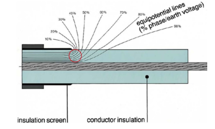
Figure 54 – Electrical equipotential lines indicating strong electric field at the screen edge
Figure 54 shows this situation, with the electric field represented by ‘equipotential lines’ joining points of equal voltage or ‘potential’. Where the equipotential lines are close together the electric field is strong.
This strong electric field at the screen edge (indicated by the red circle) would cause insulation damage and eventual electrical breakdown if nothing were done to reduce the electric stress at this position. This is why all MV joints and terminations have ‘stress control’ components whose function is to reduce the electric stress at the screen edge (and other positions of high stress) to acceptable levels.
Figure 55 shows the stress control method used from the earliest days of cable accessory development. This is a ‘stress cone’ which controls stress by positioning a conductive cone shaped component at the screen edge and thereby forcing the equipotential lines to separate exit the cable insulation more gradually. This is called a ‘geometric’ method of stress control. Stress cones for polymeric cables are made of flexible rubber and are commonly incorporated in cold-shrink or push-on accessories.
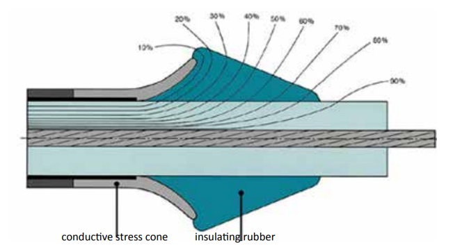
Figure 55 – Control of electric stress by a ‘stress cone’
The common alternative to a geometric stress cone is a layer of material with special electrical impedance characteristics. The stress control function will depend on the resistivity and/or high relative permittivity of the material but the result is similar to that of a stress cone, in that the electric field is graded along the length of the layer and the field strength at the screen edge is reduced. The material may have ‘non-linear’ resistivity properties similar to those of surge arresters.
Figure 56 illustrates this type of electrical stress control. The materials may be in the form of heat-shrink or cold-shrink tubings, mastics or hot-melt compounds.

Figure 56 – Control of stress by a material layer with special electrical impedance characteristics
Partial discharges and their effects
Partial discharges are localised electrical breakdowns, typically occurring in small voids within insulation. When partial discharges happen in free air, for example on the surface of insulators, they are commonly called ‘corona’.
Partial discharges within the polymeric insulation of joints and terminations are likely to result in full breakdown of the accessory at some unpredictable time during service, depending on the size and number of the discharges and the progressive damage done by them.
Effective stress control components and their correct installation will reduce the likelihood of partial discharges occurring at working voltage or test voltages. The essential part to be played by the installer is to ensure that the accessory insulation is as void-free as possible, especially in high stress areas such as near the screen edge. Best practice will involve close attention to the following.
- Ensuring that interfaces, such as those between layers of heat-shrink material, are clean and free from any contamination.
- Correctly positioning cold-shrink and push-on components that make contact with the screen edge.
- Applying adequate and uniform heating to heat-shrink components.
- Applying insulation or stress control tapes exactly as required in the installation instruction (tension, positioning etc).
Further Reading
- Cables | MV Paper Insulated v MV Polymeric Insulated Cables
- The Installation Site | MV Cable Joints & Cable Terminations
- First Steps | MV Joints, Jointers & Initial Considerations
- Cable Preparation | Jointing & Terminating Aspects of MV Cable Preparation
- Conductor Connectors | Crimp v Mechanical Connectors with Joints & Terminations
- Earth Bonding | Joints & Terminations & Overheating Prevention
- MV Cable Accessory Technologies | Heat Shrink, Cold Shrink & Push-on
- MV Cables & Causes of MV Cable Failures

LV, MV & HV Jointing, Earthing, Substation & Electrical Eqpt
Thorne & Derrick International are specialist distributors of LV, MV & HV Cable Installation, Jointing, Duct Sealing, Substation & Electrical Equipment – servicing UK and global businesses involved in cable installations, cable jointing, substation, overhead line and electrical construction at LV, 11kV, 33kV and EHV.
THORNE & DERRICK Product Categories: Duct Seals | Cable Cleats | Cable Glands | Electrical Safety | Arc Flash Protection | Cable Jointing Tools | Cable Pulling | Earthing | Feeder Pillars | Cable Joints LV | Joints & Terminations MV HV
MV Cables & Causes of MV Cable Failures
January 10th, 2020
MV Cables
As well as causing disruption to power supply, MV cable accessory failures are potentially dangerous especially if they occur in public areas such as under roads or walk-ways.
Figure 46 shows the immediate result of electrical breakdown and arcing in a cable joint installed in a manhole under a walk-way.

Figure 46 – Failure of a cable joint installed in a manhole under a walk-way
The following figures illustrate some installation faults that have already resulted in accessory failure or may do so sooner or later.
Cable Joints
Figure 47 shows a cross-section cut through a heat-shrink joint. There is a large void at the 7 o’clock position. This was caused by under-heating at this part of the circumference of the joint. The installer applied most heat between 10 o’clock and 4 o’clock positions, no doubt convenient for where he was standing. Electrical stress in the void will result in partial discharges that will probably lead to breakdown of the cable joint.

Figure 47 – Air void between layers of a heat-shrink joint
Figure 48 shows removal of a strippable screen after spiral scoring. The scoring knife has been set too deep and has cut into the underlying XLPE insulation.

Figure 48 – Cuts into XLPE insulation caused by strippable screen scoring tool blade set too deep
Figure 49 shows a heat-shrink termination that has failed by breakdown between the cable lug and the insulation screen. Electrical tracks are visible on the insulation surface and the heat-shrink sleeve has split in a number of places due to arcing. The cause of the MV cable failure may have been under-shrinking of the heat shrink tubing and/or entry of moisture at the conductor lug.
Figure 49 – Failure of a cable termination due to electrical tracking on the insulation surface
Figure 50 shows a termination (push-on or cold-shrink type) where the cable termination body covers only part of the deep-indent conductor lug. This was probably the result of mis-placement. The cable termination must seal on to the lug barrel to prevent moisture entry. In this case the seal may have been ineffective.

Figure 50 – Incomplete coverage of termination lug possibly allowing moisture entry
Figure 51 shows cable termination bushings on 12kV medium voltage switchgear.
The centre bushing has failed by surface breakdown after long-term partial discharge activity on its surface. The activity resulted from incomplete sealing of a heat-shrink insulating boot on to the bushing surface. Corrosion of the surrounding steelwork (caused by acidic gases generated by discharge activity) indicates that the electrical activity had been occurring for some time before complete failure.

Figure 51 – Failure of a switchgear bushing after long-term partial discharge activity
Figure 52 shows a heat-shrink termination on 3-core cable.
The individual cores may have been made to the correct length but the cable crutch position should be near the base of the cable box. The cores have been severely bent in order to make connections to the bushings. In addition, phase identification sleeves or any other covering should not be on the termination surface as they will interfere with the essential non-tracking function.

Figure 52 – Termination made without regard to dimensional instructions
Figure 53 shows what happens when the installer does not follow the installation instruction and does not remove the insulation screen. Unfortunately this indicates that he not only did not read the instruction but also does not understand the function of the screen and the fact that it is conductive. Electrical failure would have been immediate given that there is only nominal separation between phase voltage (conductor connector) and earth (insulation screen).

Figure 53 – Immediate failure due to insulation screen not being removed during installation
MV Cable Accessories
Thorne & Derrick, Specialist Distributors of LV HV Cable Jointing & Electrical Equipment are leading UK Suppliers of 3rd Party Type Tested MV Cable Accessories (Nexans | 3M | Pfisterer). To promote MV Cable System Integrity, we have Partnered with BASEC – British Approvals Service for Cables – their MV Cable Approval Scheme is committed to combating Non-Compliant cables entering the market-place and introducing potentially catastrophic future O&M problems.
Further Reading
- Cables | MV Paper Insulated v MV Polymeric Insulated Cables
- The Installation Site | MV Cable Joints & Cable Terminations
- First Steps | MV Joints, Jointers & Initial Considerations
- Cable Preparation | Jointing & Terminating Aspects of MV Cable Preparation
- Conductor Connectors | Crimp v Mechanical Connectors with Joints & Terminations
- Earth Bonding | Joints & Terminations & Overheating Prevention
- MV Cable Accessory Technologies | Heat Shrink, Cold Shrink & Push-on
- MV Cables | Electric Field & Stress Control
LV, MV & HV Jointing, Earthing, Substation & Electrical Eqpt
Thorne & Derrick International are specialist distributors of LV, MV & HV Cable Installation, Jointing, Duct Sealing, Substation & Electrical Equipment – servicing UK and global businesses involved in cable installations, cable jointing, substation, overhead line and electrical construction at LV, 11kV, 33kV and EHV.
THORNE & DERRICK Product Categories: Duct Seals | Cable Cleats | Cable Glands | Electrical Safety | Arc Flash Protection | Cable Jointing Tools | Cable Pulling | Earthing | Feeder Pillars | Cable Joints LV | Joints & Terminations MV HV
MV Cable Accessory Technologies | Heat Shrink, Cold Shrink & Push-on
January 10th, 2020
Installers should always receive Jointer training in the MV cable accessory technologies that they will work with.
Each technology has its own peculiarities and practice will be needed for the installer to become familiar with the individual skills needed. Installation instructions always have detailed information on cable stripping dimensions etc but not necessarily much guidance on techniques relevant to whether the accessory components are heat-shrink, cold shrink, push-on or maybe more than one technology.
The sections below highlight some important considerations for each of the major technologies used for joints, terminations and connectors at medium voltage (MV).
Heat-shrink accessories
Heat-shrinkable sleeves and moulded parts are made of special cross linked plastic materials that are heated and stretched (‘expanded’) and then cooled whilst held expanded. The expanded state becomes ‘frozen’ into the molecular structure. Extruded tubings and moulded parts are supplied in this state.
The installation process involves positioning and re-heating the expanded parts, usually with a propane or butane gas torch, until the parts shrink (‘recover’) on to whatever they have been placed (Figure 43). Because a naked flame is involved (or perhaps a powerful hot air gun), an appropriate level of installer skill is required to ensure full recovery using heat shrink torches, avoiding faults such as voids in the interfaces of insulating layers, or burning of the material surface.
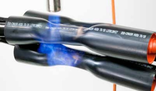
Figure 43 – Shrinking joint insulation screening tubings
Some important rules for successful installation of heat-shrink components are as follows.
- Use a gas torch designed for this purpose (not a torch designed for soldering).
- Adjust the torch to give a large soft yellow flame.
- Position part accurately as adjustment may not be possible after shrinking starts.
- Keep the flame moving around the shrinking component.
- Point the flame in the direction of shrinking.
- Do not move the accessory until the heat-shrink components have cooled.
Cold-shrink sleeves and moulded parts are also supplied in an expanded form but in this case on some form of rigid former or ‘hold-out’. The hold-out is removed during installation to allow the stretched part to recover into position on the joint or termination (see Figure 44). Cold-shrink components are usually made from soft flexible materials such as silicone rubber and EPDM.
Some important rules for successful installation of cold-shrink components are as follows.
- Check that the parts are within their ‘use by’ date.
- Keep the expanded components away from sharp objects.
- Use only the specified grease or other lubricant.
- Position the component accurately because adjustment may not be possible after recovery starts.
- Support the component in position and remove the holdout carefully and slowly without stretching the component.
- When removing spiral holdouts, the instruction may require the tape pulling position to be rotated around the cable to avoid snagging or tangling.
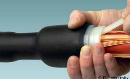
Figure 44 – Installation of a cold-shrink joint sleeve with spiral tape holdout
Push-on accessories
This is a general term referring to joints, terminations and separable connectors that are not supplied in an expanded form. Each part is sized such that it forms an interference fit with the cable and can be pushed into position, usually without the need for special tooling. These accessories are also referred to as ‘slip-on’.
There are many designs of terminations and joints in this technology category. Applications extend well beyond MV up to the highest system voltages. The most well known MV push-on accessories are fully screened separable connectors for connecting cables to electrical equipment via standardised bushings (see Figure 45).
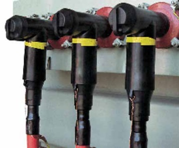
Figure 45 – Screened separable ‘T’ connectors (or ‘elbows’)
Some important rules for successful installation of push-on components are as follows.
- Check that the part is correctly sized for the cable diameter (because range-taking may be restricted).
- Apply only the lubricant supplied with the kit or recommended by the manufacturer.
- Install each component on to the cable in a single movement (do not stop part-way) into its final position.
‘Hybrid’ accessories
Some accessories comprise a mix of heat-shrink, cold-shrink and push-on components.
The recommendations applying to each technology should be followed. Some utilities favour joints that include a pourable resin. The usual function of the resin is to provide additional mechanical protection and/or moisture sealing. It is very important to follow closely the instructions for mixing and pouring of resin, including health and safety guidance for personal protection.
Further Reading
- Cables | MV Paper Insulated v MV Polymeric Insulated Cables
- The Installation Site | MV Cable Joints & Cable Terminations
- First Steps | MV Joints, Jointers & Initial Considerations
- Cable Preparation | Jointing & Terminating Aspects of MV Cable Preparation
- Conductor Connectors | Crimp v Mechanical Connectors with Joints & Terminations
- Earth Bonding | Joints & Terminations & Overheating Prevention
- MV Cables & Causes of MV Cable Failures
- MV Cables | Electric Field & Stress Control
LV, MV & HV Jointing, Earthing, Substation & Electrical Eqpt
Thorne & Derrick International are specialist distributors of LV, MV & HV Cable Installation, Jointing, Duct Sealing, Substation & Electrical Equipment – servicing UK and global businesses involved in cable installations, cable jointing, substation, overhead line and electrical construction at LV, 11kV, 33kV and EHV.
THORNE & DERRICK Product Categories: Duct Seals | Cable Cleats | Cable Glands | Electrical Safety | Arc Flash Protection | Cable Jointing Tools | Cable Pulling | Earthing | Feeder Pillars | Cable Joints LV | Joints & Terminations MV HV
