

Blog
Removing LC Shield MV Medium Voltage Cables – Alroc PF3/06
March 22nd, 2018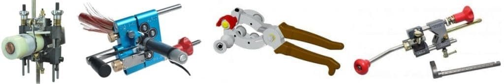
Jointers Cable Tools | Low Medium High Voltage | LV MV HV 11kV 33kV 66kV 132kV
-
Uploaded By Chris Dodds – Thorne & Derrick Sales & Marketing Manager
Cable Stripping Tool
Remove LC Longitudinally Corrugated Copper Tape Shield From High Voltage Cables
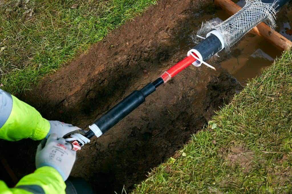
Alroc PF3/06 cable jointing tools are used by cable jointers to remove the copper tape shield from MV-HV medium/high voltage power cables.
The video demonstrates removing LC shield without scoring into the semi-conductive screen layer below the copper tape shield – the Alroc PF3/06 cable jointers tool features grooved bushings so that the cable cutting blade sits on the highest point of the LC shield.
The scoring depth is set to .3 mm to guarantee reliable cutting without accidental screen cutting or deep scoring.
Safe for the cable. Safe for the hands.
T&D stock Alroc cable jointing tools to enable the removal of outer cable sheath, XLPE insulation and semi-conductive screens (bonded and strippable).
Associated Cable Jointing Tools
♦ Alroc PG HTA Sheath Stripping Pliers – see remove cable sheath
♦ Alroc LH Insulation Stripping Tools – see remove cable insulation
♦ Alroc 8YR0-LHM Peelable Semicon Screen Removal Tools – see remove semicon screen
More
- Removing Bonded Semicon Screen 11kV 33kV Cables – Alroc CWB18-60
- Cable Peeling Tool HV High Voltage Cables – ALROC AMF5 55-160 NSCF
- MV HV Power Cables & How To Remove Fabric Layers – Some Cable Jointers Tips
- Removing Outer Sheath HV EHV Cables – Alroc DMSR/80-160

Thorne & Derrick International are specialist distributors of LV, MV & HV Cable Installation, Jointing, Duct Sealing, Substation & Electrical Safety Equipment – servicing UK and global businesses involved in cable installations, cable jointing, substation earthing, overhead line and electrical construction at LV, 11kV, 33kV and EHV.
THORNE & DERRICK Product Categories: Duct Seals | Cable Cleats | Cable Glands | Electrical Safety | Arc Flash Protection | Cable Jointing Tools | Cable Pulling | Earthing | Feeder Pillars | Cable Joints LV | Joints & Terminations MV HV
T&D Distributors | 3M | Prysmian | Nexans Euromold | Elastimold | Pfisterer CONNEX
Removing Bonded Semicon Screen 11kV 33kV Cables – Alroc CWB18-60
March 22nd, 2018Jointers Cable Tools | Low Medium High Voltage | LV MV HV 11kV 33kV 66kV 132kV
-
Uploaded By Chris Dodds – Thorne & Derrick Sales & Marketing Manager
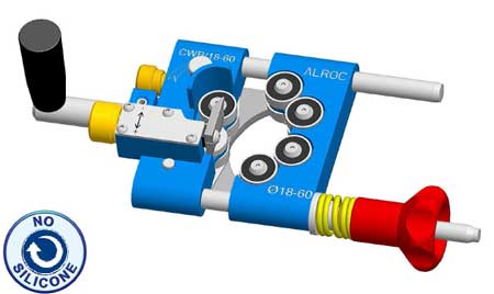
Alroc CWB18-60
Remove Bonded Semicon Screen From 11kV 33kV Power Cables
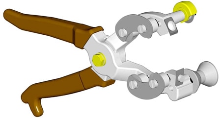
The new Alroc CWB/18-60-FEP cable jointers tool removes both the bonded semi-conducting screen without requiring lubrication while also creating a chamfer in a clean and reliable medium/high voltage cable preparation process – extensively used by jointers to prepare 11kV/33kV cables prior to the installation of MV HV Cold Shrink & Heat Shrink Joints and Terminations.
Contact T&D for Alroc tools and also a complete of cable jointing tools suitable for cable insulation removal and “easy-peel” screen stripping.
With a multitude of jointing tools available from several manufacturers, T&D decided to ask an industry expert in the jointing and terminating of MV, HV and EHV cables for an impartial and considered review of the new jointing tool manufactured by Alroc.
“Having used all types of jointing tools during my years this is by far the best and most consistent tool available. Alroc CWB/18-60-FEP has a working range of 18-60mm over the semi-conductive screen effectively covering 99% of all 11kV and 33kV MV HV power cables. The cable jointing tool design is based on rollers so no grease is needed for the cable peeling process.”
“The cutting blade can be used to chamfer the leading edge for pre-moulded HV cable terminations. Finally, the finish is another level” comments Karl McFadden (Cable Systems Application Engineer at Pfisterer).
The “Blue Tool” from Alroc creates a smooth finish to the insulation screen reducing sanding requirements by the jointer for bonded screen diameters up to 60mm. Operate using a consistent rhythm when turning the Alroc CWB/18-60 tool to achieve a smooth and clean finish without waves or “ghost-marks”.
Pictured : Alroc CWB18-60 Bonded Semi-Con Removal Tool
More
- Removing LC Shield MV Medium Voltage Cables – Alroc PF3/06
- Cable Peeling Tool HV High Voltage Cables – ALROC AMF5 55-160 NSCF
- MV HV Power Cables & How To Remove Fabric Layers – Some Cable Jointers Tips
- Removing Outer Sheath HV EHV Cables – Alroc DMSR/80-160
Thorne & Derrick International are specialist distributors of LV, MV & HV Cable Installation, Jointing, Duct Sealing, Substation & Electrical Safety Equipment – servicing UK and global businesses involved in cable installations, cable jointing, substation earthing, overhead line and electrical construction at LV, 11kV, 33kV and EHV.
THORNE & DERRICK Product Categories: Duct Seals | Cable Cleats | Cable Glands | Electrical Safety | Arc Flash Protection | Cable Jointing Tools | Cable Pulling | Earthing | Feeder Pillars | Cable Joints LV | Joints & Terminations MV HV
T&D Distributors | 3M | Prysmian | Nexans Euromold | Elastimold | Pfisterer CONNEX
Cable Peeling Tool HV High Voltage Cables – ALROC AMF5 55-160 NSCF
March 22nd, 2018Jointers Cable Tools | Low Medium High Voltage | LV MV HV 11kV 33kV 66kV 132kV
-
Uploaded By Chris Dodds – Thorne & Derrick Sales & Marketing Manager
Cable Peeling Tool (Motorised)
Remove Bonded Semicon Screen & XLPE Insulation From Extra High Voltage Cables
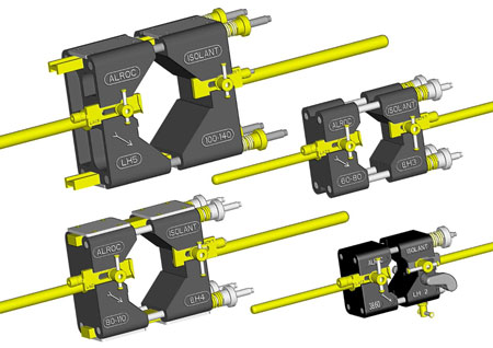
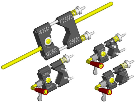
Alroc AMF5 55-160 cable peeling tools are used by HV-EHV cable jointers for the removal of XLPE insulation and shaving of semi-conductive (bonded semi-con screen) on transmission and distribution cables from 132kV up to 400kV.
Alroc AMF5 55-160 tool can be used on HV-EHV cables with an outside diameter range of 55-160mm and is designed to make the removal of high voltage polymeric cable insulation (XLPE) simple and efficient with significantly reduced sanding required by the cable jointer using a lower grit abrasive.
The cable jointing tool provides XLPE insulation removal and lengthening of the cable chamfer on the transition to enable installation of cable joints, terminations or connectors.
Alroc AMF5 55-160 is a motorised HV-EHV underground cable peeling tool used in conjunction with the Alroc BMFD/50-160 tool when chamfering HV cables – the jointing tool will perform a cable chamfer but not pencilling of high voltage power cables.
Tools also available to remove bonded screens from 11kV/33kV cables with XLPE insulation.
Cable Tool Capability
- Diameter 55-160mm
- Bonded Semicon Thickness Capacity 3mm
- Remaining Length Of The Semicon 80mm
- XLPE Cable Insulation Thickness 35mm
- Tool Guiding Ball Bearings (No Silicone Required)
Associated Cable Jointing Tools
Alroc DMSR /80-160 High Voltage Outer Cable Sheath Stripping Tool
Alroc CHN4/50-110 NS High Voltage XLPE Insulation Tapering Tool
Alroc GR I-R TE – High Voltage Bonded Semicon Scraping Tool
T&D are leading stockist for the complete range of Alroc Cable Tools for removing cable sheath, insulation and screen from LV, HV, HV and EHV power cables.
Alroc AMF5 55-160 NSCF Cable Jointing Tool
Here in the video the Alroc jointing tool is shown preparing and shaving the semicon screen on a 400kV 2500sqmm EHV cable with polymeric XLPE type insulation.
♦ Bonded Semiconductor Removal – the semicon screen is removed in a controlled and steady preparation (16 wheels rolling around the cable) effectively shaping the cable round over the XLPE insulation. A constant diameter over the XLPE insulation is achieved preventing the tool blade from digging or cutting into the insulation.
♦ XLPE Insulation Removal – the back-iron enables the cable jointer to set the pitch of the tool thus making the rotation of the cable tool easy when removing the high voltage XLPE cable insulation.
| Alroc Part Number | Cable Diameter | Tool Capacity | Cable Dimensions | Tool Packaging | |||||
| Bonded Semicon Thickness Capacity | Remaining Length Of The Semicon | XLPE Insulation Thickness Capacity | Guiding | Length | Width | Height | |||
| CAMF4/40-90-BBCF | 40 – 90mm / 1.575 – 3.543in | 2.5mm / 0.098in | 55mm / 2.165in | 35mm / 1.378in | By Ball Bearings | 460mm / 18.110in | 155mm / 6.102in | 150mm / 5.906in | Case |
| CAMF5/55-160-BBCF | 55 – 160mm / 2.168 – 6.299in | 3mm / 0.118in | 80mm / 3.150in | 35mm / 1.378in | By Ball Bearings | 700mm / 27.559in | 255mm / 10.039in | 180mm / 7.087in | Case |
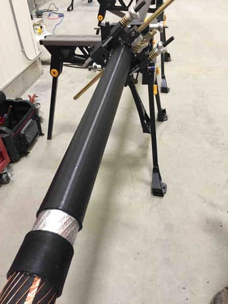
Image : Goodbye Glass. Jimmy Nicklin (HV EHV Jointer) – the Alroc AMF5 55-160 tool removes the need for HV jointers to “glass” the outer conductive sheaths as the highly precision engineered cable jointing tool provides accurate stripping of cables in a motor controlled rather than manual process.
XLPE Cables HVDC
The design and construction of the transmission grid of the future with overhead transmission lines and underground cable required to meet future demand of electricity supply has led to the development by ABB of XLPE DC cables rated higher than 500kV.
The EirGrid East-West Interconnector (EWIP) links the high-voltage power grids of Ireland and Great Britain by means of an HVDC Light interconnection. The interconnector enables Ireland to import and export power to and from Britain, thereby creating a more competitive home market and reducing consumer prices.
ABB were responsible for delivering the entire solution – including design, engineering, type testing, manufacture, civil works, cable pulling/laying, cable jointing, trenching, installation and commissioning. The video shows the loading of the high voltage cable for the project EirGrid East West Interconnector (EWIP) that took place in April 2012 in Karlskrona, Sweden.

Image: ABB. 525kV DC XLPE Cable Insulation – Extra High Voltage EHV
More
- Removing LC Shield MV Medium Voltage Cables – Alroc PF3/06
- Removing Bonded Semicon Screen 11kV 33kV Cables – Alroc CWB18-60
- MV HV Power Cables & How To Remove Fabric Layers – Some Cable Jointers Tips
- Removing Outer Sheath HV EHV Cables – Alroc DMSR/80-160
Thorne & Derrick International are specialist distributors of LV, MV & HV Cable Installation, Jointing, Duct Sealing, Substation & Electrical Safety Equipment – servicing UK and global businesses involved in cable installations, cable jointing, substation earthing, overhead line and electrical construction at LV, 11kV, 33kV and EHV.
THORNE & DERRICK Product Categories: Duct Seals | Cable Cleats | Cable Glands | Electrical Safety | Arc Flash Protection | Cable Jointing Tools | Cable Pulling | Earthing | Feeder Pillars | Cable Joints LV | Joints & Terminations MV HV
T&D Distributors | 3M | Prysmian | Nexans Euromold | Elastimold | Pfisterer CONNEX
Cable Socks – Technical Guide for Safe Cable Pulling Using Cable Socks
March 21st, 2018
Thorne & Derrick | Cable Laying & Pulling Equipment Distributors | LV MV HV
-
Uploaded By Chris Dodds – Thorne & Derrick Sales & Marketing Manager
Cable socks, sometimes called cable stockings or cable grips provide an efficient method of supporting cables for pulling and laying into open-trench or duct – this includes LV Low Voltage, MV Medium Voltage or HV High Voltage cables.
The correctly sized cable sock can be used to pull in short lengths of cable by hand (e.g. fault repairs prior to jointing).
Cable socks are re-usable tools (subject to inspection before re-use) and are not confined to cable applications but basically can be used to support or pull any cylindrical object within their grip and load carrying capacity.
Standard cable socks are manufactured from high tensile galvanised and stainless steel wire rope or Kevlar.
A skilled, hand woven construction process, coupled with individual product inspection throughout manufacture ensures a high quality product for reliable and long lasting application.
UK DNO’s generally specify according to their Engineering Standards that all pilot and telephone, LV, 11kV, 20kV, 33kV, 66kV and 132kV cables shall normally be pulled in using a correctly sized cable socks which are securely fixed to the cable. More difficult pulls may require the use of a pulling eye attached directly to the cable conductors, which has been installed by the manufacturer – cable rollers shall always be used when pulling cables.
LV MV HV
Further information on the main ranges according to voltage application for underground power cable pulling or overhead line stringing can be found here:
- LV Low Voltage & MV Medium Voltage Cable Socks & Conductor Grips 33kV
- MV Medium Voltage Cable Socks & Conductor Grips 132kV
- HV High Voltage Cable Socks & Conductor Grips 275kV – 400kV
Cable Socks
WL & FOS
The Working Load (WL) of a cable sock depends on the Factor of Safety (FOS) applied to the Minimum Breaking Load.
For example, where the operational risk is considered to be normal, it is recommended that a FOS of 5 be applied, for high risk operations a FOS of at least 10 should be considered.
The Approximate Breaking Load stated on any certification, the recommended Factors of Safety, and any implied or stated fitness for purpose, are all only applicable when the cable socks are new and unused.
There are many factors that the person using the cable sock must take into consideration when trying to calculate a safe working load as it is impossible to guarantee a suitable safety factor when there are many variables which change from cable pulling application to application.
In addition, before using any cable sock, the user must carry out a full assessment of its suitability for the proposed application, and the level of operational risk involved, including taking account of:
- size of the cable sock, in relation to the size and shape of the gripped cable
- stability of the cables when gripped
- grip surface of the cable
- anticipated path of movement, including possible obstructions
- resistive force of the cables being pulled
- minimum-breaking load (MBL) of the cable sock
- condition of the cable sock
- suitability and compatibility of any cable pulling attachments used
- environment / operating conditions
When selecting the cable sock users must allow for a 20% variance in break loads and, if there is ‘twist’ in the cable, a suitable swivel link must be used.
When the correct cable sock is selected, cable installation through cable ducts, conduits and trenches is made considerably easier. The cable sock adds little to the overall diameter of the cable and ‘free passage’ is normally available through sheave blocks and pipes.
Cable socks can often be used on a ‘new for old’ cable replacement by applying two grips on a ‘back-to-back’ basis with a solid link or swivel in between grips, allowing the old cable to be used to pull through the new replacement.
Swivel links can be used to allow for reduced torque build-up induced by the cable pulling equipment and inherent lay in the cables themselves, whether LV, MV, HV or EHV. Lace up cable socks can be applied anywhere along the cable length, preventing overloading of the cable.
To prevent winched cable pulls exceeding the maximum tension force of the cables, a cable sock fitted with a swivel can be used to connect the bond to the cable and a dynamometer used to check that the maximum pulling tension for the cable is not exceeded.
When pulling cables by mechanical cable winch, the load-limiting device must be used to ensure that the pulling tension applied to the cable does not exceed the manufacturers specified maximum permissible tensions. The pulling of cables by direct and unmonitored mechanical means (e.g. hitched to a vehicle, Land rover winch) is not permitted.
Several UK DNO’s including Northern Powergrid, specify in their Policy for the Installation of Distribution Power Cables that cable pulling by winch shall only be carried out where there is a serviceable and accurate dynamometer calibrated in kgs.

Press Release | Thorne & Derrick Appointed Approved Stockist for UK Leading Cable Pulling Equipment Manufacturer
Cable Socks – Typical Applications
- Power cable pulling – LV MV HV
- Overhead house service cables
- Portable tool supply cables
- Portable compressed air lines
- Conduit risers
- Moveable hydraulic hoses
- Cable strain relief
- Oil support cables
- Marine applications
- “Guy rope” adjusters
- Fibre optic cable applications
Pulling Overhead Power Line Conductors Using Cable Socks
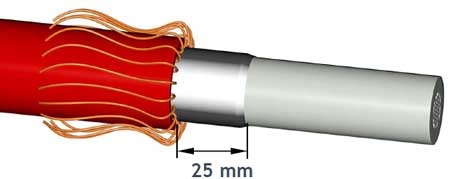
According to the Ericsson Universal Cable Handbook the most critical moment in the pulling out operation is when the cable end and cable sock passes through the line roller or suspension clamp. To make the pulling out easier the cable end should be “sectioned down” at the end before the cable sock is applied.
Between 150 – 200 mm/core is enough, see figure below.
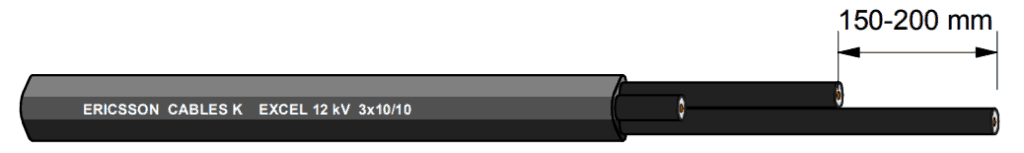
This will make the end smoother and more flexible when it passes the cable pulling devices.
If a cable sock of Kevlar is used this is more important as it is soft and does not form a natural cone the same as a galvanised steel cable sock. The cores can also be cut with a knife to avoid sharp edges which will simplify the pulling even more.
Type of Cable Socks
Single Eye Socks – available in single or double weave.
Double Eye Socks – standard support sock, with double eye. Available in single or double weave.
Lace Up Socks – cable sock for fitting at points along the length of a cable.
Open Ended Socks – socks designed to enable two cables, hoses or ropes to be connected for pulling or supporting purposes.
Single Eye Socks (Triple Weave) – high strength cable socks with heavy duty shoulders, for stringing or pulling-in non-insulated conductors on long, high voltage transmission lines, or other high load applications.
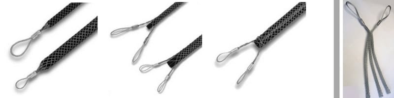
Single Eye | Double Eye | Lace Up | 11kV 33kV Triplex Cable Socks
Note : Cable socks must not to be used as primary lifting devices.
More Cable Pulling Blogs
- Cable Laying & Pulling – Installing LV-HV Cables Into Trench
- Cable Laying & Pulling – Installing LV-HV Cables Into Duct
- Cable Pulling Equipment – A Cable Laying, Duct & Installation Guide From SSE
- Cable Pulling Equipment – A Cable Duct Laying Guide From BT Openreach

Cable Pulling & Cable Laying Equipment Suppliers & Distributors
Thorne & Derrick International distribute the most extensive range of Cable Pulling & Cable Laying Equipment to enable the installation of low, medium and high voltage power cables into underground trench or duct – products also supplied for fibre optic blowing, subsea trenching, offshore umbilical installations and pulling armoured cables onto cable tray.
Contact us for 3M Electrical, ABB, Alroc, AN Wallis, CATU Electrical, Cembre, Centriforce, CMP, CSD, Elastimold, Ellis Patents, Emtelle, Euromold, Filoform, Furse, Lucy Electric & Zodion, Nexans, Pfisterer, Polypipe, Prysmian, Roxtec, Sicame, WT Henley.
Cable Blowers | Cable Lubricant | Duct Rods | Cable Socks | Cable Jacks | Cable Rollers | Cable Protection Covers MV HV | Cable Joints MV HV | Duct Sealing
Stainless Steel Cable Cleats – Preventing Galvanic Corrosion Of Cable Fixings
March 20th, 2018
-
Uploaded By Chris Dodds – Thorne & Derrick Sales & Marketing Manager
Cable Cleats
In the following article we provide an evidence based specification case for stainless steel cable cleats where levels of atmospheric corrosion preclude use of other cable fixing materials.
One of the most important issues to consider when specifying cable cleats is the risk of material corrosion – not just as a result of the installation environment, but also from other metals which the cable cleat is in contact with.
Galvanic corrosion occurs when dissimilar metals are placed in contact with each other in the presence of an electrolyte. There are two factors that affect the rate of galvanic corrosion, the first is the distance between the two metals in the galvanic series.
The further apart the two metals are in the galvanic series, the greater the risk of galvanic corrosion – with the metal higher up the list (more anodic) being the one whose rate of corrosion is accelerated.

Galvanic Series
The second factor to consider is the relative surface areas of the different metals.
If the more anodic (higher up the list) metal has a smaller surface area than the metal it is in contact with, the difference in surface area causes the rate of corrosion of the anodic metal to increase.
Conversely, if the more anodic metal has a much larger surface area than the cathodic metal, it may be sufficient for the effects of galvanic corrosion to be discounted. In terms of cable cleat selection, the surface area of the cleat is generally significantly smaller than the structure it is mounted on.
Therefore, if it is made from a metal that is more anodic than its support structure it will be susceptible to galvanic corrosion.
Conversely, if the cable cleat is more cathodic than its support structure, there is little risk of galvanic corrosion.
Using this criteria, if galvanised ladder is the support structure, and there are no other significant factors, it is safe to use stainless steel or aluminium cleats. However, if the support structure is stainless steel, separation should be provided if aluminium or galvanised cleats are used.
Galvanic corrosion is not easily predictable and can be influenced by the type of electrolytes present such as salt water or fresh water containing impurities. In general terms when guarding against galvanic corrosion, the safest course of action is to separate dissimilar metals with polymer separation washers.
This separation should be carried out between the cable cleat and its mounting surface and the cleat’s mounting fixing.
All Ellis cable cleat products constructed from dissimilar metal are designed in a way that completely avoids bimetallic contact. As a result of this you can be confident that cable cleats will have a service life measured in decades.

Emperor Cleats – stainless steel cable cleats for single or trefoil cleating of cables with highest levels of short-circuit protection. Max S/c Test Level 235kA | 225mm Cleat Spacings.
Stainless Steel Cable Cleats
All Ellis stainless steel cable cleats are produced from 316L austenitic stainless steel.
In general, cable cleats are manufactured from austenitic stainless steel due to its non-magnetic and corrosion resistant properties – the former ensuring the cable cleat will not induce eddy currents or localised heating of the LV-HV cable.
Austenitic stainless steel does become a little magnetic as a result of work hardening when processed. This magnetism can barely be detected with a magnet and so is not significant from an eddy current perspective.
304 austenitic stainless steel, often referred to as A2, is one of the most commonly used stainless steels. It has excellent corrosion resistant properties in most circumstances, although is susceptible in atmospheres where chlorides are present, making it unsuitable for use in coastal or marine environments.
316 austenitic stainless steel, often referred to as A4, contains Molybdenum, which provides resistance against chlorides. 316 is often referred to as marine grade stainless steel due to its suitability for use in coastal and offshore applications.
If unsure a simple chemical test can determine whether Molybdenum is present and so differentiate between 304 and 316 types of stainless steel.
There are many different types of stainless steel, but there are two principal variants when it comes to cable cleats. 304 and 316 stainless steel are available in low carbon variants, namely 304L and 316L. These variants are immune to sensitisation (grain boundary carbide precipitation).
Any cable cleat which is manufactured from stainless steel and includes welding in the manufacturing process should be made in a low carbon (L) variant.
Should you require any further assistance in the selection or specification of stainless steel cable cleats for LV Low Voltage, MV Medium Voltage or HV High Voltage cables please do not hesitate to contact us.

Vulcan Cleats – stainless steel cable cleats for single or trefoil cleating of cables with moderate levels of short-circuit protection. Max S/c Test Level 132kA | 300mm Cleat Spacings.
Cable Cleat Coatings
The corrosion resistance properties of stainless steel are a result of chromium, which reacts with oxygen and forms a self-healing impervious layer of chromium oxide on the surface of the steel.
In most circumstances the chromium oxide layer is extremely durable and helps in resisting galvanic corrosion. However, in certain installation locations, such as railway tunnels, the oxide layer can be continuously penetrated.
This occurs due to trains frequently applying their brakes, which releases mild steel dust into the atmosphere that then settles on the stainless steel. If moisture is present, then corrosion occurs at an exaggerated rate. In such circumstances, if regular washing is not feasible, use of aluminium as an alternative to stainless steel products and/or coating processes are strongly recommended.
Ellis Patents offers special coatings to suit specific cable installation environments – e.g. our London Underground Approved electrostatic plastic coatings.
Cable Cleat Fixings
Closure fixings on cable cleats are fundamental to the loop strength of the cable cleat and its short-circuit withstand capability.
All Ellis Patents 316L stainless steel cleats use 316 fixings, which are manufactured to a precise and specific tensile strength. Fixings are sourced directly from approved manufacturers and any fixing on any cleat is directly traceable back to the batch quality records at that manufacturer.
Galvanised Steel
Contracts often require a guarantee regarding the life expectancy of a cleat. If the installation is designed correctly and all other corrosion issues have been considered this is a relatively simple exercise for stainless steel products. With galvanized steel, life expectancy is determined by the thickness of the zinc coating.
The resistance of galvanizing to atmospheric corrosion depends on a protective film that forms on the surface of the zinc. When the newly coated steel is withdrawn from the galvanizing bath, the zinc has a clean, bright, shiny surface. With time a corrosion process occurs which produces a dull grey patina as the surface reacts with oxygen, water and carbon dioxide in the atmosphere.
This leads to the formation of a tough, stable, protective layer, which is tightly adherent to the zinc. As the corrosion process is continuous, the thickness of the zinc layer reduces over time and it is the speed of this reduction that is used to accurately predict the life span of the cable cleat.
Corrosion Rates for the UK
Permission to use the information relating to galvanising was granted by the Galvanizers Association for galvanised steel. If a galvanised steel cable cleat is specified for use in a zone 3 area then the corrosion rate is 1.5 microns (µm) per year.
If the contract for this specification states a required life expectancy of 40 years, then the initial galvanising thickness will need to be a minimum of 60 µm in order to meet the required longevity.
Zinc corrosion rates are represented by 5 categories indicated by the colour codes below:

Zinc Corrosion Rates

Corrosion Rates for the UK
Cable Cleats Blogs
- IEC 61914 – Cable Cleats & Short Circuit Protection Calculations
- Fire Resistance & Cable Cleats – Surviving Fire, Flame & Extreme Heat
- Cable Cleats – London Underground 1-085 Standard For Fire Safety Performance
LV, MV & HV Jointing, Earthing, Substation & Electrical Eqpt
Thorne & Derrick International are specialist distributors of LV, MV & HV Cable Installation, Jointing, Duct Sealing, Substation & Electrical Equipment – servicing UK and global businesses involved in cable installations, cable jointing, substation, overhead line and electrical construction at LV, 11kV, 33kV and EHV.
THORNE & DERRICK Product Categories: Duct Seals | Cable Cleats | Cable Glands | Electrical Safety | Arc Flash Protection | Cable Jointing Tools | Cable Pulling | Earthing | Feeder Pillars | Cable Joints LV | Joints & Terminations MV HV
