

➡ Richard Emery IEng MIET MIHEEM Authorising Engineer (E) IHEEM AE(E) at Green Building Design Consultants. Its a cooling medium. The oil circulates around the core and out to radiators on the sides, so aiding the cooling of the transformer core
Cable Joints & Terminations HV
Subsea Cables | MV Medium Voltage Power & Fibre Optics Cables
May 1st, 2019-
uploaded by Chris Dodds - Thorne & Derrick Sales & Marketing Manager
Subsea Cables
This document describes a Nexans standard MV Medium Voltage subsea power cable.
Optical fibres can be included upon request. Utilising the common nomenclature U0/U(Umax)1, the following voltage ratings are covered in this Subsea Cable document:
- U0/U(Umax) = 3 Phase Core 11kV 6/10(12)kV
- U0/U(Umax) = 3 Phase Core 24kV 12/20(24)kV
- U0/U(Umax) = 3 Phase Core 33kV 18/30(36)kV
Fibre Optic Core: Multiple single mode fibres (G652) are encapsulated in a protective steel tube together with a hygroscopic filling compound. The final diameter of the FO element is tuned to match the primary interstice of the main assembly by extruding an outer polyolefin cable sheath.
Cable Armour: Protective layer(s) of galvanised steel wires is applied over the inner covering. Interstices are filled by bitumen for corrosion protection – these can be prepared using approved cable cleaners. The cable armour provides axial stiffness and crush resistance. Steel wire dimensions are according to IEC60502-2 section 13, and steel wire properties according to EN10257-2 and EN10244-2. A number of steel wires can be replaced by zinc wires for additional corrosion protection.
Cable Joints, Terminations & Connectors
Complete range of Heat Shrink | Cold Shrink | Push-on type cable joints, terminations and connectors available for Medium & High Voltage MV HV subsea power cables with integral FO Fibre Optic cores from the Nexans Euromold range. See also the Prysmian FO Fibre Splice and Enclosures range for connecting and jointing FO cables.
For onshore applications please see: 11kV 33kV MV HV Medium & High Voltage Power Cables.

Subsea Cables
Cable Fault Location & Detection On Live Power Distribution Systems (Network Rail Approved)
April 29th, 2019
Locating Cable Faults
-
uploaded by Chris Dodds - Thorne & Derrick Sales & Marketing Manager
CableGuardian by Viper Innovations allows for quick electrical fault location on rail signalling power systems and displays them clearly on a user-friendly interface.
The cable fault locator traces both insulation and conductor faults as multiple units can be connected can isolating insulation faults to a section of cable and pinpointing the location of the conductor fault.
CableGuardian has the ability to send notifications via e-mail, SMS, and even voice call for serious faults such as open circuits, short circuits and intermittent faults reducing the time spent trying to locate the fault due to Spread Spectrum Time Domain Reflectometry (SSTDR).
The modular nature of CableGuardian allows for remote compliance with the Network Rail M003 Maintenance and Testing requirements.
The cable fault detector is suitable for the following locations including rail industry signalling power systems, legacy system equipment upgrades and electrical power distribution systems with ungrounded (Isolation Terra) AC pairs at working low voltages of up to 750V on Network Rail infrastructure.

CableGuardian – Cable Fault Location & Detection
CableGuardian
Cable Fault Location & Detection
Features & Benefits
- Distributed and intelligent infrastructure for cable health monitoring
- Integrity alarms and fault information direct to asset stakeholders
- Helps to avoid injury and reduce downtime through early fault detection and cable location
- Analytics facilitate proactive, rather than reactive, maintenance
- Enables faster and more accurate repair, minimising service outage
- Permits a move from a frequency based inspection regime to one driven by actual asset condition and performance
- Immediately locates and alarms the first cut during cable theft
- Enables compliance with the requirements of the Network Rail standard for Insulation Monitoring NR/L2/SIGELP/27725
- Fault tolerance built in – each CableGuardian node is a “slave” to the “Supervisor and Analytics System” – no “Master” node required
- Automatic configuration of CableGuardian nodes added or removed from the system
- Inbuilt GPS for auto-location on installation (option)
- Provides “data hub” for interfacing with IOT nodes such as weather centres and IP enabled cameras
CABLEGUARDIAN – Product specification
| Electrical | |
| Input Power Supply (wiring options): | 110V AC 47/63Hz “domestic supply” 230V AC 47/63Hz “domestic supply” Direct from Line Supply being monitored |
| Line Supply Conditions: | Voltage: 300V to 750V 1 AC Frequency: 47Hz to 63Hz Capacitance: Up to 500μF |
| Power Consumption: | 25W typical 30W maximum |
| Earth Connections: | “Reference Earth” and “Protective Earth” wired connections via cable gland to internal Earth terminal |
| Interfaces | |
| Communications Options: | Ethernet 10/100 Base-Tx 3G/4G Cellular (SIM embedded) Fibre Optic 100Base-FX, LC Duplex, 1300nm Multimode |
| Service Port (setup & configuration): | USB 2.0 Type A |
| IR Current Loop (option): | Output: 4-20mA @ ±1% (various modes available) |
| Front Panel Indicators: | Input supply on Internal power on Line open / short circuit alarm IR pre-alarm (Warning) IR alarm (Fault) IC pre-alarm (Warning) IC alarm (Fault) Downstream IR alarm |
| GPS & Cellular Aerial (option): | External mounted, dual function (IP67) |
| Measurements | |
| Network Insulation Resistance (IR): | 1kΩto 1GΩ@ |
| Directional Insulation Resistance: (via External Coil) |
1kΩto 10MΩ@ Network IC dependent |
| Response Value (Alarms) 2: | 1kΩto 10MΩ |
| Network Insulation Capacitance (IC): | 0.1μF to 150μF @±25% ±0.05μF |
| Directional Insulation Capacitance: (via External Coil) |
0.1μF to 80μF @ Network IR dependent |
| Line Voltage (True RMS): | Up to 750V1 AC @±3% ±5V |
| Line Current (True RMS): (via External Coil) |
Up to 120A @±1% |
| Line Frequency: | 47Hz to 63Hz @±1% ±0.5Hz |
| Line Power (True RMS): | ±3% ±5W |
| Line Power Factor: | -1 to +1 |
| Polarisation Index (PI): | In accordance with IEEE-43-2000 |
| Dielectric Absorption Ratio (DAR): | In accordance with IEEE-43-2000 |
| Conductor Short/Open Circuit: | Located to 98% accuracy by distance |
| Intermittent Conductor Faults: | Duration >100mS |
| Environmental | |
| Operating Temperature Range: | -25 °C to +70 °C (-13 °F to 158 °F) |
| Storage Temperature Range: | -40 °C to +85 °C (-40 °F to 185 °F) |
| Relative Humidity: | Up to 100% |
| Design Life: | Minimum 15 years operation |
| Climatic Conditions: | ‘Category T1 environment’ as defined in BS EN 50125-3 |
| Solar Radiation: | 1120 W/m2 as defined in BS EN 50125-3 |
| Shock and Vibration: | ‘Outside the track’ as defined in BS EN 50125-3 |
| Dimensions: | See diagram below (in millimetres [inches]) |
| Weight: | <10kg |
| Mounting: | See diagram below (M6 fixings) |
| Construction and Assembly: | In accordance with BS EN 61439-2 and BS 7671 |
| Ingress Protection: | IP54 as defined in BS EN 60529 |
| Fire Protection: | Category F1 as defined in BS EN 50125-2 |
| Product Standards | |
| Safety: BS EN 61010-1: | Overvoltage Category III (110/230V Mains & 750V 1 Line) Pollution degree 2 |
| BS EN 61010-2-030: | Measurement Category III |
| Electro-Magnetic Compatibility: | In accordance with BS EN 50121-5 |
| Insulation Monitoring Device: | IEC 61557-1 IEC 61557-8 |
| Network Rail: | NR/L2/SIGELP/27725 NR/L2/SIGELP/27409 |

CableGuardian – Diagram
The CableGuardian system may consist of a single node or multiple nodes, depending on the system monitoring requirements and the level of fault location granularity desired.

Data Storage & Analytics System
Rail Cable Accessories, Electrification & Installation Equipment
Thorne & Derrick stock an extensive range of 400V-33kV Rail Cable Accessories & Power Distribution Sytems including feeder pillars to contractors undertaking Low Voltage Power Distribution, HV Electrification & Substations, DC Traction & Networks, OLE and Track Feeder Cable Renewals – complete range of Network Rail PADS approved track terminations, cable joints, cable repair and connection products up to 25kV, including 3M Cold Shrink, Pfisterer CONNEX and Nexans Euromold products.
Full range of Cable Pulling Equipment & Products to ensure safe and efficient of rail cables in to cable ducts and containment infrastructure including cable troughs.

Cable Cleats | Cable Hangers | Cable Joints | Cable Glands | Cable Lugs | Cable Transits | Arc Flash Clothing
SVL’s Sheath Voltage Limiters for Protection of MV HV Cables
April 29th, 2019
SVL’s Sheath Voltage Limiters for Protection of MV HV Cables
Protecting the Cable Sheath & Jacket from Switching Surge
Source: INMR
Over the past decade, demand for longer power lines and higher current capacities for HV High Voltage power cables has required new methods of loss prevention.
Sheath Voltage Limiters also known as SVL’s provide valuable protection to expensive cable installations. They are highly reliable and effective at managing cable sheath voltage rises and the associated power flows that can result under fault conditions.
At the same time, ensuring high reliability of these lines is progressively more important.
Together, these developments have sharply accelerated application of surge protection on underground cable networks.
This article from 2012 contributed by surge arrester expert and INMR Columnist, Jonathan Woodworth, explained the surge protection scheme offered by sheath voltage limiters (SVLs) – devices intended to protect the cable jacket or cable sheath from electrical stresses during transient events.
Since high voltage cables these days are available in an array of different types and designs, for the sake of simplicity the focus here was on a single core HV cable with metallic sheath and polymeric outer sheath jacket (as in Fig. 1).
Thorne & Derrick are Approved Suppliers for ENSTO‘s Sheath Voltage Limiters, which provide overvoltage protection of Power Transmission & Distribution underground cable sheaths – this includes MV HV Medium & High Voltage Cables according to the rated voltage of the SVL’s (Sheath Voltage Limiters). We can provide excellent customer support, product selection and competitive prices with next-day delivery from extensive stocks of electrical Link Boxes.


Fig. 1 Simple HV cable showing polymeric jacket that may require surge protection
Introduction
Sheath Voltage Limiters
Growth in installation of underground cables has focused more attention on some of their potentially negative environmental effects. Because cable is often installed with metallic sheaths, current is induced onto the sheath from the primary conductor and flows directly to earth, representing a 100% loss of energy. In the process it can also raise the temperature of the cable, which then becomes a limiting factor in the system’s overload capability.

Fig. 2 Loss reduction in cable systems using segmentation and sheath voltage limiters
A common means to reduce such losses is to segment the cable sheath (as in Fig. 2). However, if segmentation is used to interrupt induced sheath current, measures must also be taken to limit voltage induced on the sheath during transient events.
Otherwise, the voltage differential between sheath and earth can exceed the cable jacket’s withstand, leading to puncture. This can become a point of moisture ingress, which can lead to long term dielectric and failure issues.

Fig. 3 Typical configuration of cable, SVL and phase arrester on transition pole with SVL mounted near bottom of cable termination

Fig. 4 Link box with 3 SVLs and cross-bonded sheaths
While a range of configurations is used to reduce losses in cable systems, (including cross-bonding of the sheaths and transposing phase conductors) segmentation along with surge protection of the cable jacket is considered the most effective.
The link box in this case is a universally used sealed junction box placed either in manholes or cabinets and that accommodates surge protectors as well as a point to cross-bond the sheaths.
Figure 4 shows a typical such link box setup that provides a location for the sheath voltage limiters as well as for cross bonding of the sheath. The phase conductors do not enter the link box, rather only the sheath or sheath extension.
The SVL
A sheath voltage limiter (SVL) is basically a surge arrester under a different terminology. It functions as surge arrester and, in most cases, is in fact a re-labelled distribution arrester.
Two examples of sheath voltage limiters are shown in Figures 5 and 6. In Figure 5, the arrester has no sheds because this particular design is intended only for use in the dry environment of a link box. By contrast, the SVL model shown in Figure 6 has sheds similar to an arrester because it is intended for outdoor application.
 used inside link boxes")
Fig. 5 Sheath voltage limiter with typical ratings 0.8 to 4.8 kV Uc (MCOV) used inside link boxes
 for use outdoors.")
Fig. 6 Sheath voltage limiter with typical ratings 4-14 kV Uc (MCOV) for use outdoors
Selecting an SVL
As stated earlier, the main purpose of the sheath voltage limiter is to clamp or limit the voltage stress across the cable jacket.
If the cable sheath is grounded at both ends, the voltage stress across the jacket is quite low during steady state and also relatively low during transients.
However, if the cable is segmented to reduce losses or if there are link boxes along the cable at locations of transposition or cross-bonding, it is important to install the SVLs here to eliminate any risk of insulation breakdown of the cable jacket or link box.
There is no standard method prescribed by IEC or IEEE for selecting the optimum rating for cable sheath/jacket protection. The following method is therefore proposed based on discussion with cable suppliers, arrester suppliers and with the aid of transient modeling of the system to determine the effects of a surge during transients.
This analysis assumes sheath segmentation is a single point bond (earthed at one end of the sheath) and an open point at the other end.
Sheath Voltage from Power Frequency Sources
Because the sheath of a cable is in such close proximity to the conductor, the voltage appearing on an open sheath can be substantial and is directly related to the current flowing through the phase conductor. This relationship applies during steady state as well as during faults.
Steps to Select the Optimum Sheath Voltage Limiter
- Determine the voltages that will appear on the sheath during transient events
- Select AC rating and TOV rating
- Check margin of protection of the selected rating
- Check the energy rating of the SVL is adequate
- Check mounting and failure mode for fit and function

Typical installation of an SVL
Figure 8 depicts an example where a 17 kA fault results in 3800 Vrms on the sheath. The most common rationale in selecting an arrester for protecting the sheath is to select an SVL with a turn-on level above the worst case induced power frequency voltage.
This means the SVL does not need to dissipate any energy during a temporary overvoltage (TOV) caused by faults. For overhead arresters, this is generally not the rule and, in those cases, the arresters are sized to conduct current during the TOV but not enough to cause it to fail. The overhead sizing rationale utilising an arrester’s TOV capability is not used for SVL selection unless it is necessary to achieve a better margin of protection.

Fig. 8 Example of sheath voltage during 27 kA fault on trefoil configured cable
Sheath Voltage Calculations
The steady state voltage gradient is the voltage that will appear along a 1 km length of sheath with 1000 amps flowing continuously and is a function of the configuration of the cable in the trench as well as its dimensions.
There are two basic trench configurations: the trefoil, comprised of three cables that are positioned equidistant from one another such that their cross-section forms an equilateral triangle; and the flat configuration whereby all cables are laid such that they are in the same plane and the same distance from one another.
If the voltage gradient is not supplied by the cable manufacturer for the configuration used, it can be calculated using relevant equations and methods derived from IEEE 575 “Guide for Bonding Sheaths and Shields of Single-Conductor Power Cables Rated 5 to 500 kV”:

Sheath Voltage Calculations
IEEE 575
The most common shield/sheath-bonding systems now in use on medium through extra high-voltage (5kV to 500kV) single-conductor shielded power cables and the methods of calculating the corresponding shield/sheath voltages and currents, when the cables are operated as part of a three-phase system, with the neutral grounded directly or through an impedance, are described in this guide.
Once the voltage gradient is known for 1 km at 1000 A, the voltage that will appear at the open end of a segment during a fault event can also be calculated. It is important to determine this voltage level because the SVL voltage rating (Uc) needs to be set just higher so that the arrester does not conduct during a fault event.
Should the surge arrester conduct in this instance, it would need a much higher energy handling capability than generally available for distribution type arresters. If it is found later in the sizing process that a lower level Uc is needed, a transient analysis will determine the SVL’s proper Uc and energy rating.
Assuming that the margin of protection will be adequate, then the Uc rating of the SVL will be greater than or equal to the voltage at the open point (Eopen), as follows:
Uc ≥ Eopen= voltage gradient x segment
length x max. expected fault current
where voltage gradient is V/km/1000A, length is in km and fault current is expressed in kA. For example, if a voltage gradient on a particular system is 200V/km/kA and the line is 2 km long with a potential of 17.5 kA, then the minimum acceptable Uc rating for the SVL would be 7000 V. Note that if the line were only 1 km long, the SVL’s minimum Uc would be half that of the 2 km long line and could be a minimum of 3500 V.
Figure 9 shows the current flow through an appropriately rated SVL on a 1 km line with the above-mentioned voltage gradient and fault current. It can be seen that only some microamps flow through the SVL, which is exactly what is desired. However if the same SVL is applied to a similar line of 2 km length, the current through the SVL would be significant (as in Figure 10) and the immediate temperature rise to failure is shown in Figure 11.

Fig. 9 Current conduction through properly sized SVL

Fig. 10 Current through improperly sized SVL with peak levels in 600 A range per half cycle.

Fig. 11 Temperature rise of improperly sized SVL showing imminent failure if breaker does not immediately interrupt fault
Therefore, when determining the proper Uc ratings for sheath voltage limiters SVLs, one cannot select one rating for all link boxes unless the lengths of all segments are equal.
Moreover, if the SVL is chosen correctly, it will not be required to absorb any significant level of energy during a system fault.
Protecting the Jacket from Switching Surge
The jacket and sheath interrupts are generally the weakest insulation in a HV power cable system. The below table shows their withstand levels as per IEEE 575.
Switching surge impulse withstand of the sheath interrupt and jacket are assumed to be similar to other insulator types and are 83% of the lightning impulse withstand rating (BIL).
When there is a switching surge event on the phase conductor of a cable, the current through it will induce a voltage on the sheath in the same way it does at steady state or during fault events, even though the wave shape is significantly different. Since the voltage and current on the conductor during a switching surge are not sinusoidal or even a simple impulse (see Figure 13), it is not possible to accurately predict the resulting voltage and current on the sheath.
Lightning impulse withstand of sheath interrupts and cable jacket:
| Typical BIL withstand of sheath interrupt and jacket kV peak (1.2×50 us wave) | |||
| System KV | Across Halves | Each Half to Ground | Jacket |
| 69-138 | 60 | 30 | 30 |
| 161-240 | 80 | 40 | 40 |
| 345-500 | 120 | 60 | 60 |
 and without (red) arrester protection on that phase.")
Fig. 13 Switching surge on phase conductor of 345 kV cable with (green) and without (red) arrester protection on that phase.
The only ways to accurately determine the actual voltage and current on the sheath are through transient simulations or real field tests. Since tests are not practical, transient simulations are really the only option and some useful rules of thumb have emerged from running such simulations:
1. If the SVL is selected to ride through a fault event with minimal to no serious conduction, then the switching surge energy withstand capability of a 10 kA rated distribution type arrester is adequate. If the SVL is not dimensioned to ride through the fault, then station class arresters may be needed.
2. If the 1000 A switching surge residual voltage is not available, then the 1.5 kA 8/20 lightning impulse residual voltage can be used for the margin of protection calculation.
In the case study used to create Figure 14, the switching surge voltage on the sheath without SVL protection would rise to greater than 100 kV. According to the above table, this is more than 40 kV above what the jacket or interrupt insulation can withstand, representing certain failure of the cable jacket. In this case, with an SVL of 9.6 kV Uc, the voltage on the sheath is limited to a maximum of 33 kV.
To calculate margin of protection during a switching surge, it is recommended that the 1000 A switching surge residual voltage be used. Since switching surge residual voltage is not a mandated test for distribution type arresters, the 1000 A residual voltage may not be available. In this case, a reasonable substitute for the switching surge voltage is the 8×20 residual voltage at 1.5 kA. For the 9.6 kV SVL used in the above study, the V1000=1000 A 30/75μs residual voltage is 28.4 kV.
From the above table, it can be seen that the BIL withstand level of the jacket for a 345 kV line is 60 kV. This means that the switching surge margin of protection (MP2) for this case is: MP2=([( BIL x .83 )/V1000 ]-1) x 100 = 111%.
 and with SVL (red)")
Fig. 14 Switching surge voltage inducted onto sheath of 345 kV cable with and without SVL protection. 3 pu switching surge on phase conductor without SVL (green) and with SVL (red)
Protecting the Jacket from Lightning Surge When lightning strikes an overhead line before the transition pole, the surge is clamped by the arrester that is universally mounted at this location and most of the surge current is diverted to earth.
However, a surge voltage of significant magnitude can travel into the cable with a moderate level of current as well. Figure 15, for example, depicts the voltage and current entering a 345 kV cable given a 100 kA lightning strike a few spans away.

Fig. 15 Voltage and current on phase conductor of 345 kV cable with 100 kA surge to phase several spans from transition pole.
Calculating margin of protection (MP1) for lightning is very similar to what is done in the case of switching surges. Here, 10 kA is used for the coordinating current and the full BIL is used for the withstand of the jacket and interrupt insulation. Using the same type of SVL as above for the switching surge calculation, the residual voltage at 10 kA is 35 kV and cable BIL is 60 kV.
Therefore, MP1=([BIL/V1000 ]-1)x100 = 71%. Again, a 9.6 kV Uc SVL will provide adequate insulation protection for the cable jacket.
➡ Further Reading
- 66kV Cable Jointer Training – A Question Of Competency Not Familiarisation
- PFISTERER CONNEX Size 4 | HV High Voltage Cable Jointer Training
- 66kV Connectors, Cables & Junctions Boxes – An Interview With Nexans
- Arc Flash Clothing & Protection For Safe Windfarm & Wind Turbine Working
LV, MV & HV Jointing, Earthing, Substation & Electrical Eqpt
Thorne & Derrick International are specialist distributors of LV, MV & HV Cable Installation, Jointing, Duct Sealing, Substation & Electrical Equipment – servicing UK and global businesses involved in cable installations, cable jointing, substation, overhead line and electrical construction at LV, 11kV, 33kV and EHV.
THORNE & DERRICK Product Categories: Duct Seals | Cable Cleats | Cable Glands | Electrical Safety | Arc Flash Protection | Cable Jointing Tools | Cable Pulling | Earthing | Feeder Pillars | Cable Joints LV | Joints & Terminations MV HV


HV Cable Joints, Terminations & Connectors
Bunding – Oil Filled Transformers, To Bund or Not to Bund?
April 25th, 2019
Transformer Bunds | Bunds for oil-filled transformers manufactured from steelwork on reduced lead time and at competitive prices from Thorne & Derrick | Contact us with your requirements | Stock, Service & Product Support
How Can We Help?
Thorne & Derrick can provide design and manufacturing services for Transformer Bunds with optional oil filters, drain valves, filter systems and ancillaries in both mild and galvanised steel (painted or unpainted) – innovative, efficient, safe and cost-effective solution for protection against leakages of insulating liquid to BS EN 61936-1:2010.
BS EN 61936-1:2010
Power Installations Exceeding 1kV a.c. Common Rules

Oil Filled Transformers
Guest Contribution: Carl A. Watkin IMEMME (Hons) I.Eng MIMMM MIET AIOSH
Carl has over 40 years experience as a Projects Director, Electrical Engineer & Project Manager in the highly regulated HSE HID hazardous and heavy industry sectors – this includes global ATEX and IECEx hazardous environment and area industries, civil tunnelling, LV MV HV utility sectors and the renewables sector.
In this original post from LinkedIn, the business and employment-oriented social media network, Carl discusses transformer bunds with gathered opinions from industry peers featured in the thread of comments below.
Bunding – Oil Filled Transformers
To Bund or Not To Bund?
by Carl A. Watkin
Question to all my fine Engineering contacts regarding oil filled distribution transformers – transformers are exempt from the UK oil storage regulations, as they are oil using (cooling) rather than storing, unless they have a conservator, holding in excess of 201lts, connected by single pipe – I see many transformer installs, including DNO installations, that do not have bunds around the transformers.
See: BundGuards | Substation & Transformer Oil Spills & Leaks Containment
What are your thoughts on bunding, or not, of oil filled transformers? What criteria would you use to assess whether to bund, or not?
➡ Neil Denbow (Director at Eden Transformer Oil). For distribution transformers yes you can but the process should be carried out by an accredited MIDEL Service Partner (we were the first). For power transformers yes but with referral to M&I Materials. There have been many successful retrofills around the world – MIDEL 7131

Contact Applied Power Engineering
➡ Usually sealed distribution transformers up to 630-800 kVA don’t need to be bunded.
➡ Neil Denbow (Director at Eden Transformer Oil). Manuel, BS EN 61936-1:2010 doesn’t differentiate between breathing and hermetically sealed transformers, it is defined by the volume of oil in the transformer.
➡ (Richard Emery IEng MIET MIHEEM Authorising Engineer (E) IHEEM AE(E) at Green Building Design Consultants). I get the transformer bunding problem, and even if you don’t have an oil storage problem, and the environment agency have incorrect information there is the risk assessment? Is a spillage going to cause secondary contamination, disruption and damage? How do we deal with external transformers/ bunding and rain water? I have seen some bunded walls with 300mm of water in them others with drain taps left on.
➡ Neil Denbow (Director at Eden Transformer Oil). Richard, larger 11kV transformers will have oil/water separation systems, smaller transformers will have valve with a oil/water capture filter that allows water to pass through but trap oil. We sell the latter on our website www.edenoil.co.uk and have a partner for the lager systems:- When a bund has not been maintained or doesn’t have filter system, we offer a bund emptying service.
➡ We’ve put in from full on concrete swimming pools, active filters to perspex shields around the rads to stop fluid spraying past the bund. Most of the time midel is used these days which doesn’t have the same environmental issues, a bund with a filter seems to be what we do most though.
➡ Neil Denbow (Director at Eden Transformer Oil). Dan, you are right that MIDEL is readily biodegradable but BS EN 61936-1:2010 doesn’t differentiate between oil, synthetic or natural esters. However, insurance companies do.
➡ This has been debated many times in the Rail industry. With respect to Environmental Agency website error, certain parties in Rail industry have received same letter from Environmental Agency but certain representatives contradict each other in their response.
➡ Derrick Stableford P.Tech.(Eng.) (Electrical, Instrumentation and Controls Designer at Associated Engineering). Funny I had a containment question at work this week. Sorbweb matting would be my answer for leak control. Most trannys at this level have level switches as options, the hard part is the comms back to the control centre, without creating a cyber security intrusion risk. The sorbweb Mat adsorbs oil, and repels water. No need for a shed. Using food grade oil will also help with environmental risks. You could fry your lunch with a drawn off sample, or bang it in your diesel. The bunding and double wall systems have their own cost adders and maintenance issues, Inc water pump outs and disposal. Mechanical separators can freeze and fail, esp. here at severely minus temps.
➡

Contact Applied Power Engineering
➡
➡ Karl R (Functional Safety & Systems Engineer). Watch out for an error in the HSE publicised “Hierarchy of Controls” leaflet. The vitally important area of physical isolation was missed. The hierarchy is actually: 1 Eliminate – do it a different way that doesn’t use the hazardous methods or substances. There’s no risk if there’s no hazard. No need to mitigate for a non existent hazard. Save effort, money and time for use elsewhere. 2 Substitute – use something non/less hazardous 3 Isolation – Physical separation. Barriers, bunds, locked areas and vessel containment. Dual layers. 4 Design – Automation, control, monitor, report and safely shutdown/reroute. Engineered solutions to mitigate hazardous situations and prevent hazardous material release. Control and safety systems to look after the process. Switchgear protection. 5 Admin – Enforcement and training. Emergency Response Procedures. Authorised areas, Competency, Risk Assessments, Design Reviews, Method Statements, verification and validation, maintenance, etc. 6 PPE
➡ There’s a regulation in the 18th edition where it covers transformers containing oil shall be bunded or pitted to distinguish any potential fires


Thorne & Derrick stock and supply the DrainEezy range of transformer bund filters for use with LV MV HV Oil-Filled Transformers providing passive, self-regulating environmental protection and preventing bunds from overflowing during rainfall events; the DrainEezy Bund Filter System is field-ready to fit and retrofittable allowing clean water to drain freely while automatically blocking and retaining insulating oil in the event of a leak or catastrophic transformer failure.

600/1000V | 11kV | 33kV | 66kV Transformer Bund Filters
Fire Walls & Fire Risk Hazards Of Electrical Equipment – BS EN 61936-1 : 2010
April 16th, 2019BS EN 61936-1:2010 Fire Walls
The following information and clauses concerning fire walls is extracted from BS EN 61936-1:2010.
Power Installations Exceeding 1kV a.c. Common Rules
8.7 Protection Against Fire 8.7.1 General
Relevant national, provincial and local fire protection regulations shall be taken into account in the design of the installation.
NOTE: Fire hazard and fire risk of electrical equipment is separated into two categories: fire victim and fire origin.
Precautions for each category should be taken into account in the installation requirements.
- precautions to fire victim:
- space separation from origin of fire;
- flame propagation prevention:
physical layout of the substation,
liquid containment,
fire barriers (e.g. REI fire-resistant materials 60/90),
extinguishing system;
- precautions to fire origin:
- electrical protection;
- thermal protection;
- pressure protection;
- fire resistant materials.
Care shall be taken that, in the event of fire, the escape and rescue paths and the emergency exits can be used (see 7.1.6).
The user or owner of the installation shall specify any requirement for fire extinguishing equipment. Automatic devices to protect against equipment burning due to severe overheating, overloading and faults (internal/external) shall be provided, depending on the size and significance of the installation.
Equipment in which there is a potential for sparks, arcing, explosion or high temperature, for example electrical machines, transformers, resistors, switches and fuses, shall not be used in operating areas subject to fire hazard unless the construction of this equipment is such that flammable materials cannot be ignited by them.
If this cannot be ensured, special precautions, for example fire walls, fire-resistant separations, vaults, enclosures and containment, are necessary.
Consideration should be given to separating different sections of switchgear by fire walls. This can be achieved by means of bus ducts which penetrate the fire wall and which connect the sections of the switchgear together.
8.7.2 Transformers, Reactors
In the following sub-clauses, the word ‘transformer’ represents ‘transformers and reactors’.
For the identification of coolant types, see 6.2.2.IEC 61100 classifies insulating liquids and transformer oils according to:fire point and net caloric value (heat of combustion).
Three classes have been defined:
Class O, if the fire-point is less than or equal to 300 °C. (e.g Mineral Oil).
Class K, if the fire-point is above 300 °C. (e.g MIDEL 7131 and MIDEL eN 1024).
Class L, if the insulating liquid has no measurable fire-point.(e.g. Xiameter PMX-561).
IEC 60076-11 classifies dry-type transformers in terms of their behaviour when exposed to fire. The fire hazard associated with transformers of outdoor and indoor installations is dependent on the rating of the equipment, the volume and type of insulating mediums, the type and proximity and exposure of nearby equipment and structures.
The use of one or more recognized safeguard measures shall be used in accordance with the evaluation of the risk.
♦ IEC 60076-11:2018 Power Transformers – Part 11: Dry-type Transformers
NOTE: For definition of risk, see ISO/IEC Guide 51.
Common sumps or catchment tanks, if required, for several transformers shall be arranged so that a fire in one transformer cannot spread to another. The same applies to individual sumps which are connected to the catchment tanks of other transformers; gravel layers or pipes filled with fluid can, for example, be used for this purpose.
Arrangements which tend to minimize the fire hazard of the escaped fluid are preferred.
8.7.2.1 Outdoor Transformer Installations
The layout of an outdoor installation shall be such that burning of a transformer with a liquid volume of more than 1,000 litres will not cause a fire hazard to other transformers or objects, with the exception of those directly associated with the transformer. For this purpose, adequate clearances, G, shall be necessary.
Guide values are given in Table 3. Where transformers with a liquid volume below 1,000 litres are installed near combustible walls, special fire precautions may be necessary, depending on the nature and the use of the building.
If automatically activated fire extinguishing equipment is installed, the clearance G can be reduced.
If it is not possible to allow for adequate clearance as indicated in Table 3, fire-resistant separating walls with the following dimensions shall be provided:-
a) between transformers (see Figure 6) separating walls. For example EI 60 in accordance with the Official Journal of the European Community, No. C 62/23:
height: top of the expansion chamber (if any), otherwise the top of the transformer tank;
length: width or length of the sump (in the case of a dry-type transformer, the width or length of the transformer, depending upon the direction of the transformer);
b) between transformers and buildings separating walls. For example EI 60; if additional fire separating wall is not provided, fire rating of the building wall should be increased, for example REI 90 (see Figure 7) in accordance with the Official Journal of the European Community C 62/23.
Table 3 – Guide Values For Outdoor Transformer Clearances
| Transformer Type | Liquid Volume | Clearance G to | ||
| Other transformers or non-combustible building surface (m) | Combustible building surface (m) | |||
| Oil insulated transformers (O) | 1000 <…..< 2000 | 3 | 7.5 | |
| 2000 <…..< 20000 | 5 | 10 | ||
| 20000 <…..< 45000 | 10 | 20 | ||
| < 45000 | 15 | 30 | ||
| Less flammable liquid insulated transformers (K) without enhanced protection | 1000 <…..< 2000 | 1.5 | 7.5 | |
| ≥3800 | 4.5 | 15 | ||
| Clearance G to building surface or adjacent transformers | ||||
| Less flammable liquid insulated transformers (K) without enhanced protection | Horizontal (m) | Vertical (m) | ||
| 0.9 | 1.5 | |||
| Dry-type transformers (A) | Fire behaviour class | Clearance G to building surface or adjacent transformers | ||
| Horizontal (m) | Vertical (m) | |||
| F0 | 1.5 | 3.0 | ||
| F1 | None | None | ||
NOTE 1: Enhanced protection means:
- tank rupture strength
- tank pressure relief
- low-current fault protection
- high-current fault protection
For an example of enhanced protection, see Factory Global standard 3990 (33) or equivalent.
NOTE 2: Sufficient space should be allowed for periodic cleaning of resin-encapsulated transformer windings, in order to prevent possible electrical faults and fire hazard caused by deposited atmospheric pollution.
Three classes have been defined:
Class O, if the fire-point is less than or equal to 300 °C. (e.g Mineral Oil)
Class K, if the fire-point is above 300 °C. (e.g MIDEL 7131 and MIDEL eN 1024)
Class L, if the insulating liquid has no measurable fire-point.(e.g. Xiameter PMX-561)
8.7.2.2 Indoor Transformer Installation In Closed Electrical Operating Areas
Minimum requirements for the installation of indoor transformers are given in Table 4.
Table 4 – Minimum Requirements For The Installation Of Indoor Transformers
| Transformer Type | Class | Safeguards |
| Liquid Volume | ||
| ≤ 1000 I | El 60 respectively REI 60 | |
| ≤ 1000 I | El 90 respectively REI 90 or El 60 respectively REI 60 and automatic sprinkler protection | |
| Less flammable liquid insulted transformers (K) | Nominal power/max | |
| Without enhanced protection | (no restriction) | El 60 respectively REI 60 or automatic sprinkler protection |
| With enhanced protection | ≤ 10 MVA and UM ≤ 38 kV | El 60 respectively REI 60 or separation distances 1.5m horizontally and 1.5m vertically |
| Dry-type transformer (A) | Fire behaviour | |
| F0 | El 60 respectively REI 60 or separation distances 0.9m horizontally and 1.5m vertically | |
| F1 | Non combustible walls | |
NOTE 1: REI represents the bearing system (wall) whereas El represents the non-load bearing system (wall) where R is the load bearing capacity, E is the fire integrity, I is the thermal insulation and 60/90 refers to time in minutes.
NOTE 2: Enhanced protection means:
- tank rupture strength
- tank pressure relief
- low-current fault protection
- high-current fault protection
For an example of enhanced protection, see Factory Global standard 3990 (33) or equivalent.
NOTE 3: Sufficient space should be allowed for periodic cleaning of resin-encapsulated transformer windings, in order to prevent possible electrical faults and fire hazards caused by deposited atmospheric pollution.
Doors shall have a fire resistance of at least 60 min. Doors which open to the outside are adequate if they are of low flammability material. Ventilation openings necessary for the operation of the transformers are permitted in the doors or in adjacent walls. When designing the openings, the possible escape of hot gases shall be considered.
8.7.2.3 Indoor Transformer Installations In Industrial Buildings
For all transformers in industrial buildings, fast-acting protective devices which provide immediate automatic interruption in the event of failure are necessary.
Transformers with coolant type O require the same provisions as in 8.7.2.2.
For all other liquid-immersed transformers, no special arrangements in respect of fire.
protection are required, except for the provisions for liquid retention in case of leakage and the provision of portable fire extinguishing apparatus suitable for electrical equipment.
Dry-type transformers (A) require the selection of the correct fire behaviour class depending on the activity of the industry and on the material present in the surroundings. Fire extinguishing provisions are advisable, particularly for class F0.
NOTE: For all transformers in industrial buildings, additional fire precautions may be necessary, depending on the nature and use of the building.
8.7.2.4 Indoor Installations In Buildings Which Are Permanently Occupied By Persons
In high-voltage installations, located in public or residential buildings, special conditions shall be observed in accordance with existing standards or national regulations.
8.7.2.5 Fire in the vicinity of transformers
If there is an exceptional risk of the transformer being exposed to external fire, consideration shall be given to
- fire-resistant separating walls;
- gas-tight vessels capable of withstanding the internal pressure generated;
- controlled release of the hot liquid; fire extinguishing systems.
8.7.3 Cables
The danger of the spread of fire and its consequences shall be reduced, as far as possible, by selecting suitable cables and by the method of installation.
The cables may be assessed by reference to the following categories:
- cables without particular fire performance characteristics;
- cables (single) with resistance to flame propagation (IEC 60332 series);
- cables (bunched) with resistance to flame propagation (IEC 60332 series);
- cables with low emission of smoke (IEC 61034-1);
- cables with low emission of acidic and corrosive gases (IEC 60754-1 and IEC 60754-2);
- cables with fire-resisting characteristics (IEC 60331-21 or IEC 60331-1).
Cables in trenches and buildings shall be laid in such a way that the regulations regarding fire safety of the building are not adversely affected. For example, to avoid fire propagation, holes or cable ducts through which the cables go from one room to another shall be sealed with suitable fire proof and resistant material.
A physical separation or different routing of power circuits from the control circuits for high voltage equipment is recommended if it is necessary to preserve the integrity of the latter as long as possible following damage to the power circuits.
Where necessary, a fire alarm and fire extinguishing systems shall be installed in cable tunnels and in cable racks in the basement of control buildings.
8.7.4 Other Equipment With Flammable Liquid
For all equipment, such as switchgear which contains more than 100 l of flammable liquid in each separate compartment, special fire precautions as specified for transformers may be necessary, depending on the nature and use of the installation and its location.
Figure 6 – Separating Walls Between Transformers
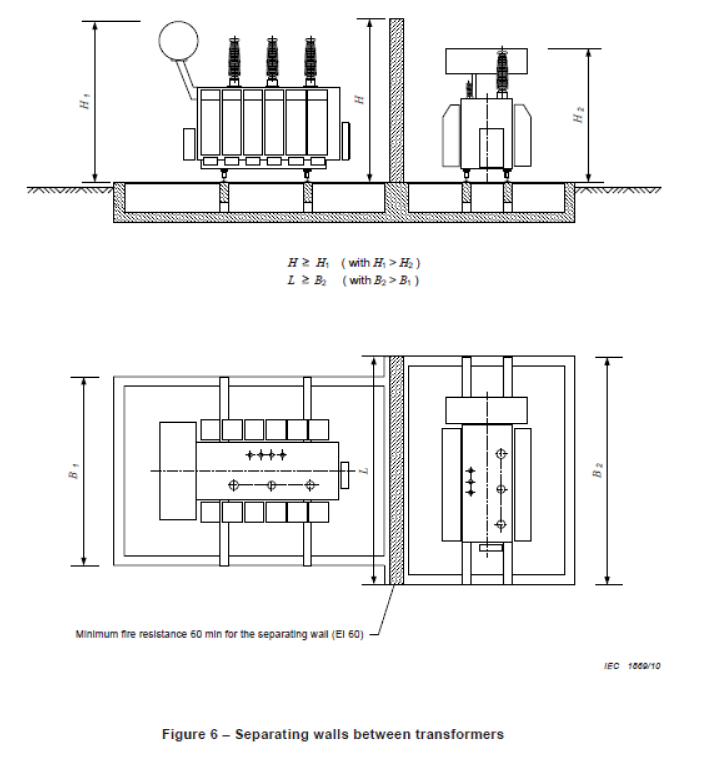
Figure 7 – Fire Protection Between Transformer & Building
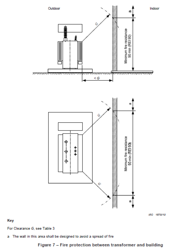
Key
For Clearance G. see Table 3
a) The wall in this area shall be designed to avoid a spread of fire
Further Reading
Transformer Oils – 11kV 33kV 66kV Substation Transformer Oil Refilling, Sampling & Analysis
Utilising Distribution Transformers To Optimise Solar
11kV Transformers | Introducing Amorphous Core HV Transformers
VIDEO How To Verify Total Absence of Voltage By The Push Of a Button
THORNE & DERRICK SPECIALIST ELECTRICAL DISTRIBUTOR
The 11kV Specialists
Thorne & Derrick distribute the most extensive range of 11kV Cable Jointing, Terminating, Pulling & Installation Equipment – we service UK and international clients working on underground cables, overhead lines, substations and electrical construction at 11kV and up to and EHV transmission and distribution voltages.
- Key 11kV Products: MV-HV Cable Joints & Terminations, Cable Cleats, Duct Seals, Cable Transits, Underground Cable Protection, Copper Earth Tapes, Cable Jointing Tools, Feeder Pillars, Cable Ducting, Earthing & Lightning Protection, Electrical Safety, Cable Glands, Arc Flash Protection & Fusegear.
- Distributors for: 3M Cold Shrink, ABB, Alroc, Band-It, Catu, Cembre, Centriforce, CMP, Elastimold, Ellis Patents, Emtelle, Furse, Lucy Zodion, Nexans Euromold, Panduit, Pfisterer, Polypipe, Prysmian, Roxtec.

LV – Low Voltage Cable Joints, Glands, Cleats, Lugs & Accessories (1000 Volts)

MV HV – Medium & High Voltage Cable Joints, Terminations & Connectors (11kV 33kV EHV)
Cable Laying – Underground Cable Covers, Ducting, Seals & Cable Pulling Equipment
T&D, CATU Electrical Safety & Arc Flash Protection Specialists for SAP’s, Linesmen, Jointers & Electrical Engineers – Largest UK Stockist

➡ James Hoare (LHW Partnership – Electrical & Energy Engineers). I thought the only way to get round was outdoor enclosure with class C or cast resin – when cast resin were first coming in they were welcome in buildings as an alternative to MIDEL as no need to bund the transformer.
➡ Neil Denbow (Director at Eden Transformer Oil). James, Class K insulating liquids such as the MIDEL range have the higher fire protection and are also readily biodegradable (unlike oil). However BS EN 61936-1:2010 doesn’t distinguish between the different liquids. By the way, as MIDEL Service Partners, we offer a mineral oil to MIDEL 7131 retrofill service. Click here for more information.
➡ James Hoare (LHW Partnership – Electrical & Energy Engineers). Neil – thank you – I used to work for GEC many …moons ago and we used to make distribution transformers dry and liquid – in those days Midel was a GEC group company so know it well . GEC became Alstom and think it’s now Schneider at this volts !!!
➡ Carl A. Watkin Neil, can you directly replace oil with MIDEL, one for one? I was told by Schneider that retrofit would involve fitting larger rads to the transformer as the volume of Midel required, per transformer KVA unit, to achieve the same cooling properties was higher?