

Blog
Step-by-Step Guide for a 33kV T-Boot Termination
August 8th, 2025In this guide, Harvey Ross (HV Harv) demonstrates the key stages of a 33kV T-boot termination on a Nexans GT1 incomer. This process requires accuracy to ensure a watertight seal, maintain insulation integrity, and meet manufacturer specifications. Using specialist tools – including the Ripley Tools, US15 Pro Max, US02 & US10, as well as the ALROC LH2 – Harvey shows how each stage can be completed efficiently and to a high standard. All tools featured are available from Thorne & Derrick, jointing tool stockists, suppliers & distributors, trusted by HV professionals worldwide. The video below shows the full process, with our step-by-step breakdown following.
jointing Tools Used in This T-Boot Termination
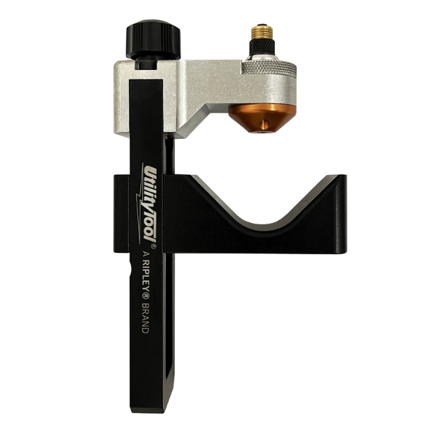
Ripley US15 Pro MAX
High-precision insulation removal tool designed for fast, consistent results on medium and high-voltage cables.
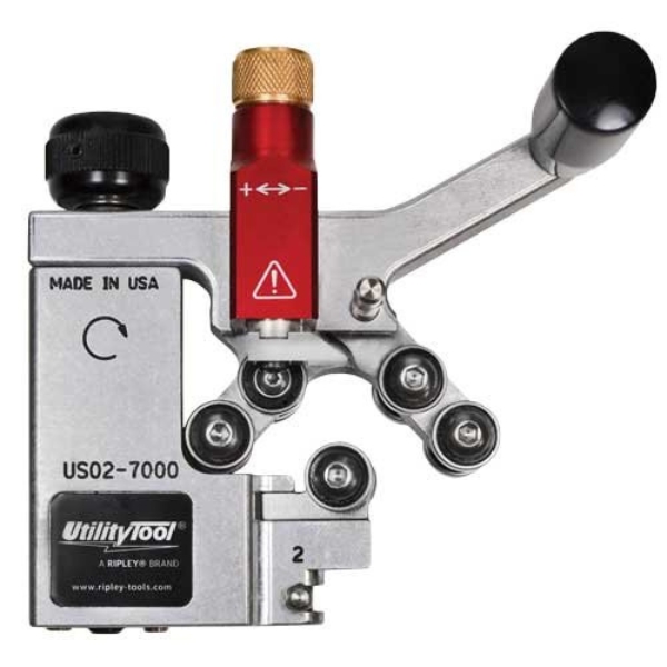
Ripley US02
Reliable semi-con screen removal tool ensuring smooth, damage-free stripping for high-voltage cable preparation.
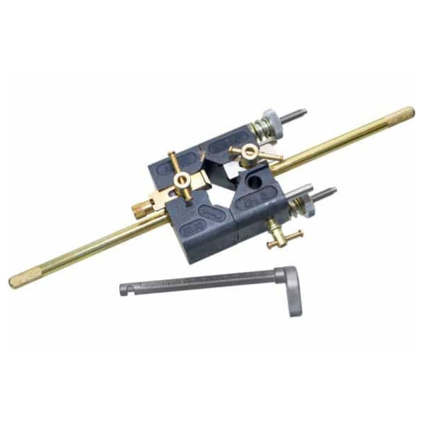
Ripley US10
Lightweight tool engineered for quick and precise chamfering of conductor ends to improve termination quality.

Alroc LH2
Heavy-duty cable cutter with a flexible cutting head for easy access to cables in confined spaces.
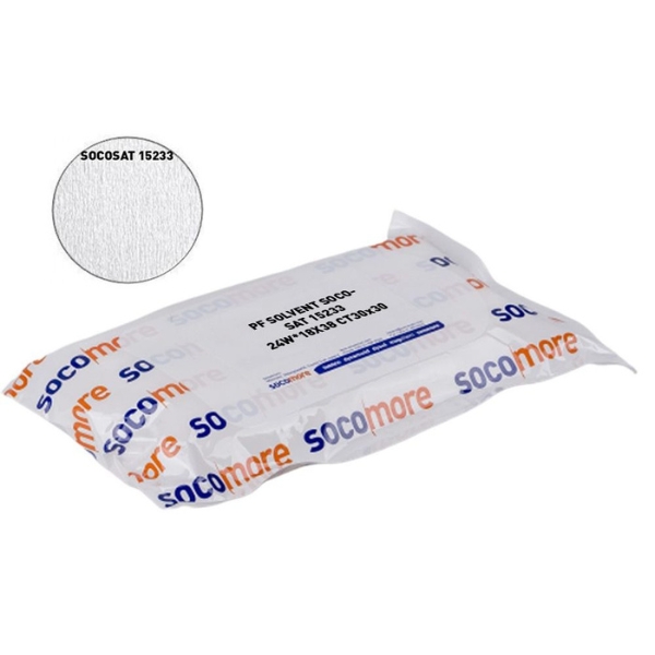
PF CLeaning Wipes
Industrial-grade wipes for effective cleaning and surface preparation during cable jointing and termination work.
All of these tools are available from Thorne & Derrick (Power and Cables) – trusted by LV, MV & HV professionals for safety, precision, and performance.
Cable Preparation & Initial Measurements
-
Measure the Bushing
-
Begin by measuring the bushing depth.
-
Measure back 285mm from the bushing end.
-
Sand 65mm of insulation to ensure a watertight seal.
-
-
Clean the Surface
-
Wipe the prepared surface thoroughly with a PF cleaning wipe.
-
XLPE Insulation Removal with Ripley US15 Pro Max
-
Remove Outer Insulation
-
Use the Ripley US15 Pro Max to make a circumferential cut, then transition to a spiral cut.
-
This tool excels in tight spaces and removes thick insulation with ease.
-
-
Finish the Cut
-
Use a hooked cable knife (a “hold-to-fall knife”) to flick out the final insulation section.
-
-
Remove Water Barrier & Copper Tape
-
Strip off the water blocking layer.
-
Remove the copper binding tape.
-
Clean the outer sheath again with a PF wipe.
-
Install Mastic & Prepare the Screen
-
Apply Water Mastic
-
Apply mastic around the cable as per kit instructions.
-
-
Bend Back Copper Screen Wires
-
Fold the screen wires back neatly in preparation for earth bonding.
-
Stress Control & Semi-Con Removal
-
Measure for Stress Control Tube
-
Mark 65mm from the screen cut to guide the positioning of the stress control tube.
-
-
Remove Semicon Layer
-
Use the Ripley US02 to remove the semi-conductive layer down to 30mm.
-
Tie off and sand as necessary for a smooth surface.
-
Cable Stripping & Chamfering
-
Strip Primary Insulation
-
Using the ALROC LH2, set the blade to the depth of the lug barrel.
-
Strip the insulation cleanly.
-
-
Chamfer the Conductor
-
Use the Ripley US10 to add a smooth chamfer to the end of the insulation.
-
This compact tool creates a clean finish, reducing stress points.
-
-
Prep Conductor
-
Tape the conductor end to prevent strand splay.
-
Clean the insulation and apply the termination grease (usually supplied with the kit).
-
Connector Assembly & Final Termination
-
Install Stress Control Tube
-
Slide it down to the 65mm marker created earlier.
-
-
Install Lug
-
Prep the conductor.
-
Slide on the lug and shear it off according to manufacturer torque ratings.
-
Clean and reapply grease.
-
-
Fit the T-Boot
-
Apply termination grease to:
-
The lug
-
Stress control tube
-
Inside of the T-body boot
-
-
Slide the boot on facing the correct direction.
-
Final Steps: Earth Bonding and Securing
-
Mount the Termination
-
Push the booted termination onto the bushing.
-
Fit the cleat to secure the assembly.
-
-
Dress Earth Wires
-
Straighten and align the copper screen wires.
-
Use one wire to wrap and secure the bundle for a clean finish.
-
Complete 33kV T-Boot Termination
What you now have is a fully installed Nexans 33kV T-boot termination, completed with precision using high-quality Ripley cable preparation tools.
Want to place an order for the tools used in this termination? Contact our team of experts – offering 40+ years of industry experience, we distribute the most extensive range of 11kV 33kV 66kV MV HV Medium & High Voltage Cable Joints, Terminations & Connectors from manufacturers including Südkabel, 3M, Prysmian, Nexans Euromold, Elastimold, Pfisterer CONNEX & SEANEX and Shrink Polymer Systems.
Why Should You Separate Electrical Cables?
July 22nd, 2025
Separating electrical cables
Prevent Trip Hazards with CableSafe Safety Hooks
Thorne & Derrick supply a comprehensive range of Safety Tools and Equipment to support safe working practices across industries including construction, renewables, data centres, rail, manufacturing, and the oil, gas, and petrochemical sectors. We also offer a specialist range of Push Pull Tools designed to reduce hand injuries and enhance workplace safety.
Separating electrical cables isn’t just good practice—it’s essential for ensuring safety, system performance, and regulatory compliance. Whether you’re working in industrial, commercial, or residential settings, here are five key reasons why cable separation matters:
Cable & Electrical Safety
When power cables are bundled together tightly, they can generate excessive heat. If not properly ventilated or separated, this heat can lead to insulation damage, short circuits, or even fire hazards. Separating cables helps reduce this risk and ensures safer operation.
Electromagnetic Interference (EMI) Reduction
Electrical cables, especially those carrying high current, emit electromagnetic fields. If signal or communication cables run too closely alongside power cables, they can pick up unwanted interference. Separating them helps maintain signal integrity and reduces noise or data errors in sensitive equipment.
Ease of Maintenance & Troubleshooting
Organised and separated cables make it easier to identify, inspect, or replace specific lines when necessary. This reduces downtime during maintenance and makes installations more professional and manageable.
Prevention of Mechanical Damage
When cables are tangled or stacked together, there’s a higher chance of bending, pulling, or abrasion—especially during equipment movement or vibration. Separation prevents wear and tear and extends the cable lifespan.
Compliance with Electrical Standards
Many safety codes and regulations (like NEC, IEC, or OSHA standards) recommend or require physical separation between certain types of cables, especially in industrial or hazardous environments.

CableSafe Safety Hooks in Use Preventing Trip Hazards and Ensuring Electrical Cable Separation on Industrial Walkways

Cable Safety Equipment | Cable Stand | Cable Bridge | Cable Rail | Cable Guard | Dropped Object Prevention Mats
Cable Management Practices
Separating electrical cables is not just about tidiness—it’s a fundamental part of designing safe, efficient, and reliable electrical systems. Whether you’re an installer, maintenance engineer, or system designer, adopting good cable management practices is a small step that can make a big difference.
Looking for reliable cable management solutions?
Thorne & Derrick are UK specialists in electrical safety equipment. Contact our team for expert advice or to request a quote on CableSafe hooks and other safety tools.
PENTA MTAG | Enhancing Rail Safety with High Voltage Detectors
July 21st, 2025
PENTA MTAG
High Voltage Detector
Now Available from Thorne & Derrick
At Thorne & Derrick, we support the UK rail industry by supplying safety-critical technology designed to protect workers and infrastructure. As an authorised distributor of PENTA Electrical Equipment, we provide a range of innovative products that enhance rail safety across the medium and high voltage power network (MV HV) – the voltage detectors are used to ensure electrical safety on typical voltage distribution systems at 11kV, 25kV, 33kV and 66kV.
Maintenance engineers working on high-voltage railway networks now have a powerful new tool to ensure their safety during critical maintenance operations.
One such product is the PENTA MTAG — a smart high voltage detector recently featured in Rail UK News.
The PENTA MTag is a state-of-the-art voltage detector designed specifically for proving dead on high-voltage distribution systems from 1kV to 69kV, including the 25kV railway network commonly used in overhead line electrification systems.
Developed to meet IEC standards and refined through feedback from industry experts, the PENTA MTag offers unparalleled reliability, durability, and ease of use, providing maintenance crews with confidence when verifying the absence of voltage.

Voltage Detectors | Pictured MV Voltage detector MTAG from PENTA | These voltage detectors are designed for “proving dead”, making sure that nominal voltage is actually absent on a circuit in a high voltage distribution system between 1kV and 66/69kV (no-voltage verification).
What is Penta MTAG?
The PENTA MTAG is a portable, intelligent high-voltage detection system that offers workers in the rail industry a reliable method of confirming that overhead lines are de-energised before work begins. With automatic detection and clear visual/audible alarms, PENTA MTAG enhances electrical safety for teams working on or near electrified tracks.
This technology is a step forward in improving protection during routine maintenance, emergency repairs, and infrastructure upgrades on 25kV OLE Systems.

Key Features
-
Non-contact high voltage detection
-
Automatic activation when magnetically attached to the conductor
-
Failsafe warning system with high-visibility LED lights and audible alerts
-
Rugged, compact design built for the rail environment
-
Lightweight and easy to deploy in seconds
Engineered for safety in real-world conditions
Railway maintenance often takes place in demanding environments, where visibility, weather, and noise can interfere with safety checks. The PENTA MTag has been designed with these challenges in mind.
Its 100 dB sound signal can be heard even in heavy traffic or high winds, thanks to a natural acoustic horn that amplifies the sound. In addition, the voltage detection device features a wide-angle visual indicator that remains clearly visible in all common working environments, including direct sunlight and fog. The innovative optic ring design ensures visibility even from the side, improving awareness of the whole team at the job site.
Built to withstand the rigors of outdoor use, the PENTA MTag features a sealed, watertight electronics compartment that prevents moisture ingress, ensuring long-term reliability. Maintenance crews and safety teams will appreciate the direct access to the battery, which simplifies replacements and minimises downtime – complete range of extendable and telescopic insulating and operating poles are available.

Engineer installs PENTA MTAG high voltage detector on overhead power line using hot stick
A game-changer for railway maintenance
Safety is paramount in high-voltage railway maintenance, and the PENTA MTag addresses the specific needs of engineers working on 25kV overhead line systems. The voltage detection device has been optimised to ensure that maintenance crews can quickly and confidently verify no-voltage conditions before conducting work, minimising risks associated with high-voltage circuits.
Its reliable detection capabilities even in railways stations or multiple parallel lines, and durable design, make it a trusted tool for maintenance professionals working on railway networks around the world.
Designed with the user in mind
 “The PENTA MTag is the result of years of feedback from maintenance professionals,” said Bill Earlie, Commercial Manager for PENTA UKI. “We’ve developed a tool that meets the exacting safety standards of the railway industry while ensuring ease of use and long-term reliability.
The PENTA MTag offers audible and visual feedback that cuts through the noise and visibility challenges faced by railway maintenance engineers every day.”
PENTA is a leader in the development of high-voltage testing equipment for critical sectors such as railways, energy utilities and Industries. With, a commitment to innovation and reliability for safety and performance, PENTA continues to develop products that meet the evolving needs of maintenance professionals worldwide.
Why Choose PENTA?
PENTA is a UK-based manufacturer of specialist safety equipment for the rail and electrical engineering sectors. Their solutions are trusted by Network Rail and contractors nationwide to meet the highest standards of safety and compliance.
Thorne & Derrick – Your Rail Safety Partner
We supply the full range of PENTA products including:
-
MTAG High Voltage Detectors
-
Insulated Tools & Rail-Specific PPE
Whether you’re working trackside, in depots, or on infrastructure upgrades, Thorne & Derrick can help you specify and supply the correct Medium & High Voltage equipment to protect your people and operations.

Staying Safe on the Tracks: Electrical Safety in the UK Rail Industry
July 18th, 2025
Ahead of Rail Live, PENTA was featured in the official Rail Live preview – a testament to their commitment to electrical safety and innovation in the UK rail sector.
As the UK rail network continues to expand and electrify in pursuit of greener, more sustainable transport, the safety of workers operating near high-voltage infrastructure has never been more important. Electrical safety equipment plays a critical role in ensuring that rail engineers, technicians, and maintenance personnel can carry out their work without compromising their wellbeing or the operational integrity of the network. One of the most critical aspects of this is the effective use of electrical safety equipment.
At Thorne & Derrick, we are proud to supply PENTA’s cutting-edge electrical safety solutions — trusted worldwide by major rail operators and utility companies.
For expert advice, technical support, or to request a quotation on PENTA Electrical Safety Products, contact Thorne & Derrick — the UK’s leading specialist distributor of electrical safety equipment for the rail industry.
Electrification of the UK Rail Network
A significant portion of the UK rail network is powered by electricity, primarily through overhead line equipment (OLE) and third-rail systems. These OLE systems typically support high-voltage – up to 25,000 volts AC on overhead lines and 750 volts DC in third-rail systems.
These systems are the backbone for greater transportation and reduced environmental impact. As such, they require careful monitoring and protection, not only for the smooth operation of the network but also for the safety of personnel and the public.
The Role of Electrical Safety Equipment
Reliable electrical safety equipment is vital for professionals exposed to high-voltage environments. This includes workers conducting routine inspections, maintenance, fault-finding, and emergency response.
One of the leading providers of such solutions is PENTA, a company renowned for its pioneering work in electrical safety systems. Their advanced electrical test and measurement devices are indispensable for workers operating near energised equipment. This unique solution is tailored for professionals engaged in maintenance, rescue operations, switching, pruning, and other activities in high-risk electrical environments.
A key advantage is the ability to address critical risk factors such as unplanned proximity to voltage sources, untagged work zones, or mistakenly energised circuits.
PENTA’s safety equipment is designed for day-to-day maintenance workers to safely address the risks and keep service disruptions to a minimum. They make the worksite safer by automating tasks like tension testing and voltage detection.
By introducing electrical test equipment indoors and outdoors, rail operators are better positioned to reduce workforce downtime and increase service safety. These devices are designed to stand up to harsh conditions and are tailored to ensure accurate, repeatable results under stress.
One device developed by PENTA for rail-specific use is the Overhead Line Tester Kit.
Designed to test conformity to international standards (specifically to Operational Safety in the Rail Industry (RIS-0703-NK Issue 01) and the British Standard BS EN 50110).
Key Products for the Rail Sector
-
Overhead Line Tester Kits – Designed for rapid voltage presence detection with multi-level alerts, visual indicators, and high-visibility displays
-
Temporary Earthing Devices – Ensure safe access to electrified infrastructure during maintenance
-
CTS Tension Meter – Provides real-time measurements of catenary wire tension to prevent failures and improve reliability
-
Smart Voltage Detectors – Enable safe, remote voltage presence testing with wireless functionality and data logging
These tools are crucial for both planned maintenance and emergency response, helping to minimise downtime, prevent accidents, and improve overall network reliability.
Safe operation of the rail system
The use of these systems supports the safe operation of services. Equipment such as circuit breakers, surge arresters, and grounding systems are designed to protect lives, infrastructure and expensive rolling stock from severe damage during electrical faults.
Real-time monitoring of electrical status helps to significantly reduce the risks associated with scheduled and unscheduled maintenance, allowing workers to complete tasks before serious failures create service disruptions or injuries.
The CTS Tension Meter provides precise, real-time measurements of tension in overhead catenary systems, ensuring that rail infrastructure meets the highest standards of safety and reliability, offering unmatched precision and ease of use for rail engineers and technicians.
The CTS Tension Meter has already garnered interest from key players in the rail industry, with several major rail networks adopting the technology to enhance both inspection and maintenance routines. By providing real-time, accurate data, the CTS allows operators to make informed decisions, helping them avoid costly disruptions and accidents caused by incorrect tension on the contact wire.
Regulatory framework & training
The UK’s Office of Rail and Road (ORR) mandates strict adherence to health and safety regulations, including the Electricity at Work Regulations 1989.
These laws require employers to ensure electrical systems are properly maintained and not to present danger. This includes a practical role to prevent all personnel working with or close to energised systems or who may accidentally encounter live equipment using proper equipment use, and emergency procedures.
Rail safety leaders also continue to reflect the importance of up-to-date equipment and following established safety protocols.
Embracing Electrical Safety innovation
With advancements in technology, the rail industry is seeing improvements in the reliability of voltage presence meters and fault detection systems. Smart systems now offer GPS location services, cloud-connected monitoring and automation tools. All powered by secure software platforms.
Not only reduce the risk of accidents but also improve the efficiency of maintenance and safety procedures. Innovations such as sensor-equipped gloves and IoT-enabled alerting kits that report deployment status in real-time – is a glimpse into how the future of rail safety is becoming both smarter and more connected.
The UK rail industry’s commitment to electrifying large stretches of the network to drive sustainability comes with several challenges. Providers like PENTA are helping to provide cutting-edge tools that address those challenges head-on – protecting the people that power the operational backbone of our rail system.
Contact Thorne & Derrick
Whether you’re planning overhead line maintenance, upgrading your safety protocols, or responding to a network emergency, we’ll help ensure your team is equipped with the most advanced, compliant, and reliable electrical equipment available.
We supply the full range of PENTA Solutions, including:
-
Voltage Detection Systems
-
Overhead Line Testing Kits
-
Conductor Wear & Tension Monitoring Tools
-
Temporary Earthing Equipment
-
Personal Protection Solutions
High Voltage Cable Drum Trailers for Utility Projects
July 10th, 2025
High Voltage Cables
Kicking of H2 with another CD500 manufactured by SEB International Ltd to support Utility project cable-pulls at 132/400kV, bound for the Grid – this is our largest Cable Drum Trailer build to date. An outstanding achievement in UK manufacturing excellence and Distributor partnership to lead the powering of global projects.
Customised to client specification to handle HV Cable Drums – should you require assistance with the Pull-in, Cable Termination, Jointing & Energisation of HV Cable Networks please continue to contact our Team. With global electricity demand forecast to double by 2050, Thorne & Derrick are perfectly positioned to meet all your major project constructions and cable fault repair works – our business can now provide technical specifications, competitive pricing and delivery commitments to enable transformer, switchgear and overhead line connections from 600V to 66/132kV polymeric cables up to 2000sqmm.
Further Case Applications
- Cable Drum Trailer Manufactured for Major High Voltage Power Project
- Cable Drum Handling | Jack Towers for LV to EHV Cable Lifting & Site Handling

