

Blog
How to Size High Voltage Earthing Conductors Correctly
October 15th, 2018
A Guide To High Voltage Earthing Conductors
-
Guest Blog by Ian Griffiths - Principal Partner at GreyMatters
What size earthing conductors should I use?
And, is there a simple table I can use for this high voltage earthing design?
These are great questions that I’m often asked. This post answers these questions together with the choice of conductor materials and jointing method within a high voltage earthing design project.
Assessing conductor size is entirely dependent on the electrical configuration and the load that the conductor must take. For example, an above-ground bonding conductor serves to transfer current with minimal voltage drop, from A to B.
A directly buried conductor has an additional purpose, that of leaking the fault current/voltage into the local geology (as part of an electrode).
When considering Lightning, the same conductor above might also see a high-frequency component and which will impose yet another requirement.
High Voltage Earthing Conductors
Design Considerations
In IEEE-std80ƒ Guide for Safety in AC Substation Grounding, section 11 – states the basic requirements are:
Each element of the grounding system, including grid conductors, connections, connecting leads, and all primary electrodes, should be so designed that for the expected design life of the installation, the element will
a) Have sufficient conductivity, so that it will not contribute substantially to local voltage differences.
b) Resist fusing and mechanical deterioration under the most adverse combination of a fault magnitude and duration.
c) Be mechanically reliable and rugged to a high degree.
d) Be able to maintain its function even when exposed to corrosion or physical abuse.
Earthing Materials
Copper has traditionally been the go-to material for years in high voltage earthing because it is not only highly conductive but also resistant to most sources of in-ground corrosion.
Similarly, aluminium has sufficient conductivity but suffers from in-ground corrosion, and the oxidation that forms around its surface is not conductive, therefore, compromises the conductor’s ability to leak current when buried, which is why buried aluminium conductors is a no-no.
Stainless steel or mild steel (when appropriately coated – galvanised or copper bonded), on the other hand, may not have the conductivity of copper or aluminium but it is sufficiently conductive to be utilised as a buried conductor.
Dealing with the Heat
So now we’ve covered the materials that are widely used for high voltage earthing.
Point ‘b’ from IEEE-std 80 above calls for the conductor to retain its mechanical strength when being exposed to a fault.
Conductors get hot when current flows through them. And they will potentially be at their hottest when subjected to a fault from the electrical system. This fault means the conductor needs to maintain its physical integrity as temperature increases and not transform into a shower of hot molten metal!
Up to this point, we’ve discussed conductor conductivities, materials and thermal-mechanical characteristics.
Another consideration for high voltage earthing is the method of the joint between conductors.
Conductor Joints
Joints in conductors are as critical to current-flow as the conductors themselves. The jointing method must not allow the joint to introduce excessive resistance. Therefore, the selection of the jointing method will impact the earthing system’s thermal resilience massively. This thermal resilience is why welded joints are the go-to choice for the high voltage earthing system.
Welded joints achieve the nearest physical match to the native conductor itself and are the gold-standard in conductor jointing because they accomplish a molecular similarity to the native material’s conductivity, as well as similar mechanical robustness.
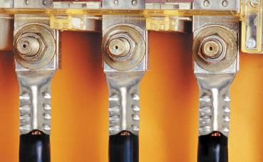
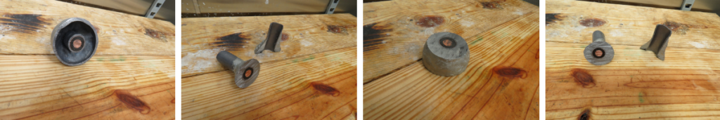
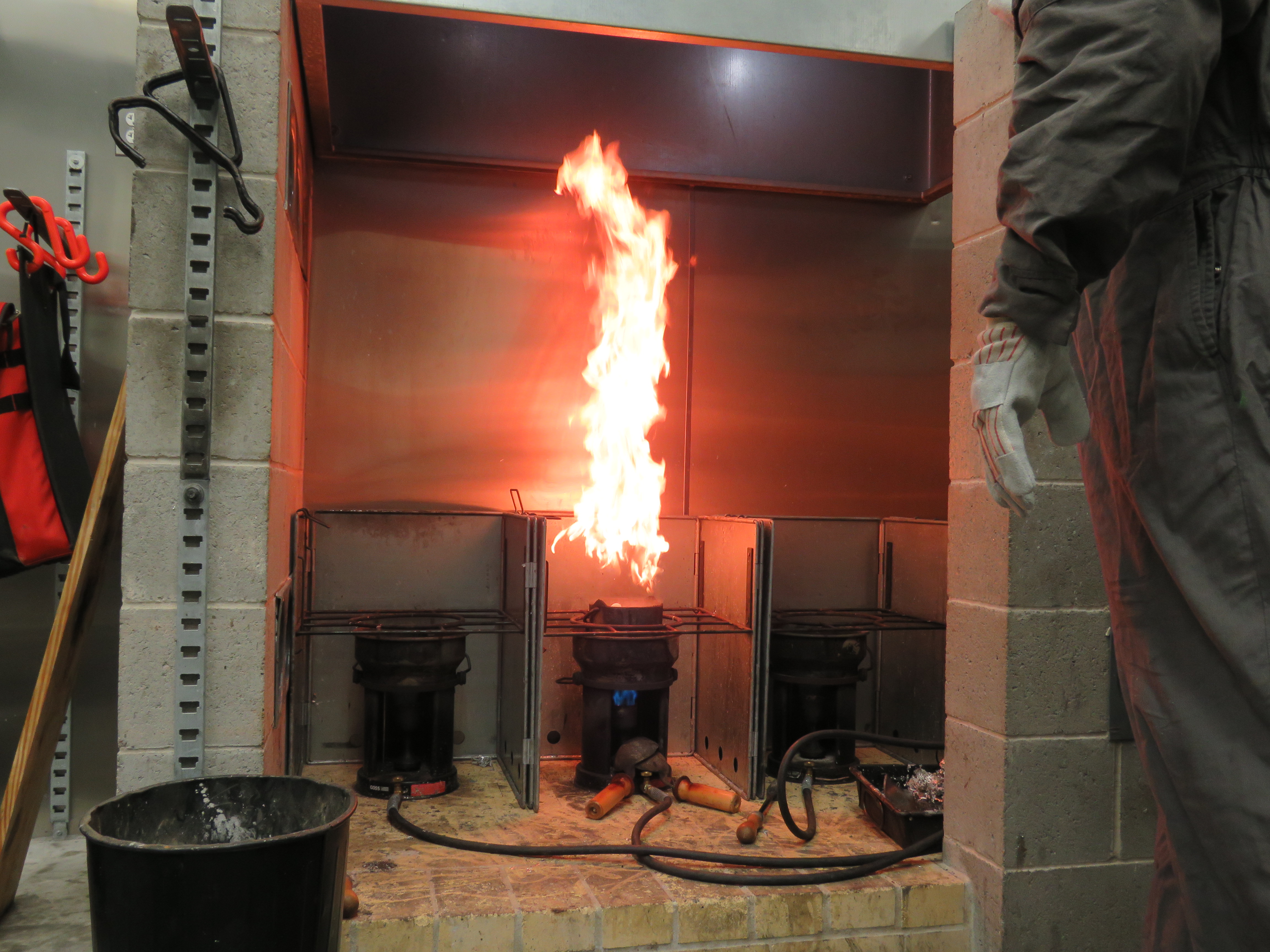
Here’s an example of a safe method of igniting an exothermic weld.
A Word of Caution
Bolted joints and clamps are made up of multiple parts which can creep and loosen over time. Loosening will add resistance across conductor joints, which as previously mentioned… is not a good thing (thermal runaway is a topic for another day).
Bolted joints fall into the category of mechanical joint methods and have a derating factor to keep the conductors operating at lower temperatures. When designing a high voltage earthing system, this means the seemingly unrelated selection of jointing method will also impact the conductor size calculation.
IEEE adiabatic equation
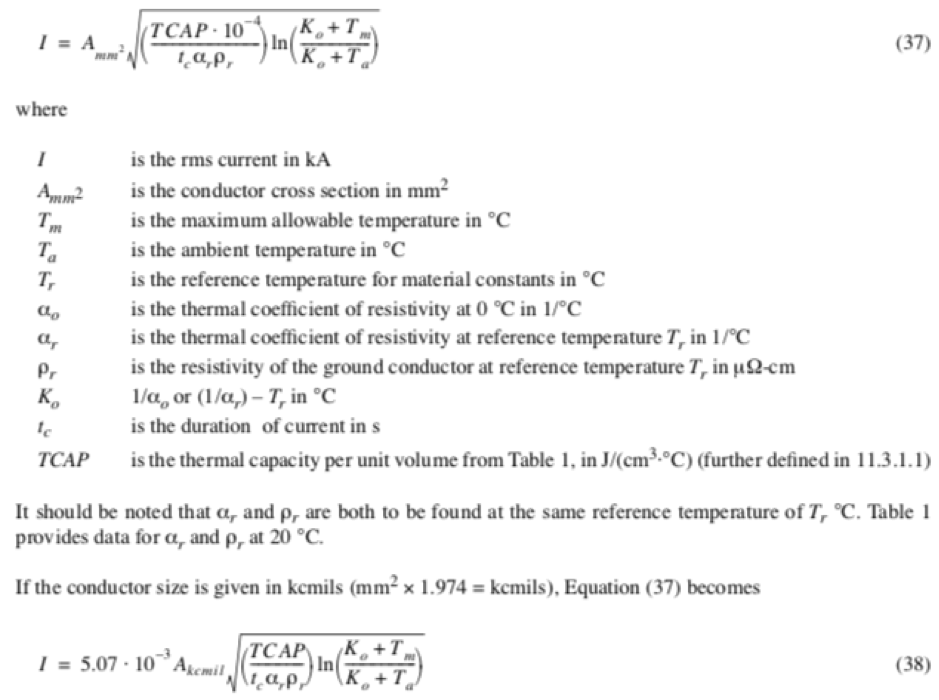
Calculating High Voltage Earthing Conductors
In Summary
So there you have it. Without going into great detail, the following factors influence conductor sizing:
- The magnitude and duration of fault current (i.e. the heat source)
- The method used for the joint
- The conductor material
- The conductor’s role in the high voltage earthing design
These factors may vary project by project, so, using a particular size of the conductor on a previous project does not mean that the same will apply to the next project, which means calculating conductor sizes (adiabatic equation) to fit the particular requirements of the project is usually very necessary.
ƒ IEEE P80 – Guide for Safety in AC Substation Grounding
This guide is primarily concerned with outdoor ac substations, either air-insulated or gas-insulated. With proper caution, the methods described herein are applicable to indoor portions of such substations, or to substations that are wholly indoors. No attempt is made to cover the grounding problems peculiar to dc substations. A quantitative analysis of the effects of lightning surges is also beyond the scope of this guide.
Further Reading
- High Voltage Earthing & Grounding System Design Protecting Lives
- Safer Exothermic Welding With Apliweld Remote Electronic Ignition
- Data Centre Earthing
Ian Griffiths CEng, MBA, BEng, MIET
Principal Engineer at GreyMatters, an Earthing & Lightning Protection Consultant of 27 years, one of the top 1% UKAS accredited CDEGS consultants and professional advisor to international utility companies, data centre and infrastructure developers. Risk Assessment Surveys and measurements for substation earthing or generation schemes on your electrical earthing system, voltages from 1kV to 765kV are undertaken by their highly qualified engineers.
Some LinkedIn Comments
Charles Shannon Senior Application Engineer at IMCORP
Hey Chris Dodds and Ian Griffiths – Substation Earthing. Great subject. I would add two minor clarifications to that blog. #1 when mentioning buried earthing conductors it’s worth clarifying that is for unjacketed cables. Additionally there in the maximum energy calculation note that with proper surge arresters this energy can be significantly reduced which can significantly reduce the size and thus the cost of the cable.
Ian Griffiths – Substation Earthing
Hi Charles, you might be right to add an additional clarification re buried conductors. Still, the piece is intentionally brief (so it’s not intended to be a definitive reference covering all the nuances), still, it does make the clear distinction between above-ground and below-ground conductors to try and get people to think about there being TWO differing purposes that an identical-sized conductor can have i.e. to either leak current (into the geology) or to transfer it (equipotn)… or a combination of both – Oh, that’s 3 but hey. So, for the sake of simplicity, it might be better to leave coatings for another blog 😉
Earth Mats | Earth Plates | Earth Rods | Earth Bars | Earth Tapes | Exothermic Welding from T&D, The Earthing Equipment & Lightning Protection Eqpt. Distributors
11kV Heat Shrink Cable Joints – BS6622 Single Core XLPE AWA Cable
October 12th, 2018
- Application: 11kV Heat Shrink Cable Joints
- Cable Type: BS6622 Single Core XLPE Insulated AWA Armoured Cables
- Cable Jointer: Neill Burns HV/LV Cable Jointer at BICS Ltd
- By: Dan Rapley (Shrink Polymer Systems – Manufacturer of LV / MV Cable Joints, Terminations, Cable Accessories)
Working alongside their Specialist Distributor Thorne & Derrick has enabled Shrink Polymer Systems to support them and their clients on UK and international LV MV HV Cable Jointing & Installation projects up to 33kV.
Thorne & Derrick based in the UK are leading suppliers LV MV HV Cable Jointing, Installation, Earthing, Substation & Electrical Equipment.
Collaborating together as a team we have been able to offer cable jointing guidance, solutions and provide an abundance of bespoke cable joint and splicing solutions for some very unique and non-standard cable combinations and constructions, including Okonite and flexible trailing joints for Protolon cables.
Our decades of experience through LV-HV cable accessory testing, product knowledge and assisting on site engineers and cable jointers has allowed us to discover and produce quality products to facilitate specific jointing applications for subsea power cables (inclusive of fibre optic cores), LSF fire resistant cables and BS/IEC standard XLPE, EPR, PILC, or PICAS medium/high voltage power cables – this includes trifurcating, transition and trifurcating-transition jointing kits for the connection of modern technology polymeric insulated Triplex cables to traditional paper insulated lead covered cables (PILC).

Pictured below are 3 single phase Shrink Polymer Systems single core XLPE armoured 11kV cable joints installed in a very tight cable duct with confined space working and restricted working space for the jointer to position and set the cables prior to heat shrinking the joints.
Note the outer protection, heavy wall, heat shrink tubes have been fully shrunk to the outer cable sheath of the 11kV power cable with no raised or “unshrunk” edges.
There are no scorches or heating damage to the heat shrink outer sleeve demonstrating excellent flamework by the jointer when using the gas torch – the flame must always be on the move never applying heat to the same area for too long.
The armour cage for the AWA has been neatly fitted to provide earth continuity of the cable armour using armour earth clamps.
The cable joint’s slim and short length design has assisted the cable jointer to enable the 11kV circuit to be jointed and installed between the two steel beams in challenging worksite conditions – trefoil cable cleats are installed to protect and restrain the 11kV cables in the event of a short circuit situation.
Neill had never used SPS cable joints before but is one of the many Jointers who have been able to benefit from Thorne and Derrick’s excellent customer service to be able to arrange “same day kit and despatch” of our heat shrink jointing products.
Contact Thorne & Derrick to provide competitive prices, technical support and immediate delivery of LV MV HV Joints & Terminations from extensive stocks to UK and international destinations.

Heat Shrink Straight Joints – jointing 11kV voltage single core cables with XLPE insulation, copper tape screen and aluminium wire armour AWA according to BS6622, the 185sqmm stranded copper conductors were connected using mechanical shearbolt connectors.
Thorne & Derrick Specialist Electrical Distributor
LV ♦ MV ♦ HV
T&D distribute the most extensive range of LV, MV & HV Cable Jointing, Terminating, Installation & Cable Pulling Equipment – we service UK and international clients working on underground cables, overhead lines, substations and electrical construction at LV, 11kV, 33kV and EHV transmission and distribution voltages.
To see and follow more Cable Jointing Blogs go to LinkedIn and follow the Thorne & Derrick company page.
- Key Products: MV-HV Cable Joints & Terminations, Cable Cleats, Sealing Cable Ducts, Cable Transits, Underground Cable Protection, Cable Jointing Tools, Feeder Pillars, Cable Ducting, Earthing & Lightning Protection, Electrical Safety, Cable Glands, Arc Flash Protection & Fusegear.
- Distributors for: 3M, ABB, Alroc, Band-It, Catu, Cembre, Centriforce, CMP, Elastimold, Ellis Patents, Emtelle, Furse, Lucy Zodion, Nexans Euromold, Pfisterer, Polypipe, Prysmian, Roxtec.
")
LV – Low Voltage Cable Joints, Glands, Cleats, Lugs & Accessories (1000 Volts)
")
MV HV – Medium & High Voltage Cable Joints, Terminations & Connectors (11kV 33kV EHV)

Cable Laying – Underground Cable Covers, Ducting, Seals & Cable Pulling Equipment
More…
T&D’s Power Blog covers: LV MV HV & EHV Transmission & Distribution, Substations, Switchgear, Cable Jointing & Termination, Cable Fault & Repair, Underground Cables.
♦ See also – ABB 132kV Surge Arresters
➡ Visit Power Blog.

Indent Crimping Of Cables – Benefits & Limitations
October 11th, 2018
Indent Crimping Of Cables – Benefits & Limitations
-
uploaded by Chris Dodds - Thorne & Derrick Sales & Marketing Manager
Thorne & Derrick International, based in the UK, are leading suppliers of cable crimp lugs and associated crimping tools for Low, Medium & High Voltage Cables and Power Systems – this series of articles by Klauke discusses the theory and practise of installing compression type cable lugs and connectors for use with copper and aluminium conductors.
Klauke cable lugs and crimping tools are used by Jointers, Linesmen, Panel Builders and Electrical Engineers to install underground cables and overhead line conductors on power, transmission and distribution networks including LV MV & HV systems, 11kV-33kV.
➡ Download 2018 Klauke Cable Lugs catalogue and see the complete range of tools for cutting and crimping cables.
In this Article we cover the following:
- W-crimp and indent crimp for different cross-sections
- The permitted cable spectrum for indent crimping comprises both Class 2 multistranded copper conductors, as well as Class 5 and Class 6 fine and ultrafine-stranded types in accordance with VDE0295 up to a cross-section of 400sqmm
- Klauke F cable lugs for ultrafine and fine-stranded conductors avoid fraying
- Practical crimping method for small cross sections below 6sqmm and also in switch cabinet construction up to 1000V
Indent crimping
Well-tried yet reliable?
Benefits & Limitations: the oldest form of electrical connection, indent crimping has proven its worth in countless electrical cable termination applications. Yet for some time now, experts have been repeatedly asking the question: is indent crimping reliable?
Why this uncertainty?
Today, hexagonal crimping is considered to be the technical standard that has generally become established. But indent crimping is considered to be an acceptable and a reliable form of cable crimping that is preferred for switch cabinets of up to 1000V.
Indent crimping is still a reliable form of crimping cables, often used in the construction of switch cabinets up to 1000V.
Indent crimping is a purely manufacturer specific type of crimping.
In other words – the manufacturer must ensure that a standardised cable crimp can be produced using its components. Leading manufacturers demonstrate this through appropriate tests.
In tests to IEC 61238, for example, Klauke proved its crimping tools and cable lugs combined can be used to make connections of equivalent quality to a hexagonal crimp.
Warning: unlike hexagonal crimping, indent crimping is suitable only for processing copper. In terms of technology, indent crimping is set apart by its high degree of compaction.
The greater impact forces, however, cause high material stress. So it‘s important to remember that connections caused by indent crimping are always strain relieved.

Indent crimping allows multistranded, fine-stranded and ultrafine-stranded conductors to be permanently connected
The variants are W-crimp and indent crimp. There are two different versions of indent crimping in use:
- the W-crimp for cross-sections from 0.5sqmm to 16sqmm
- the indent crimp for cross-sections from 6sqmm to 400sqmm
Types Of Indent Crimp

The W-crimp is ideal for smaller cross- sections, since the material in the region of the two tips of the crimp insert is extremely highly compacted

Indent crimping is especially suitable for cross-sections from 6sqmm to 400sqmm
The W-crimp is preferred for smaller cross sections, since the material in the region of the two tips of the crimp insert is extremely highly compacted. Indent crimping is commonplace and generally accepted for processing small cross-sections, since the hexagon crimp is normally used only from cross-sections upwards of 6sqmm.
For multi-stranded, fine-stranded and ultrafinestranded copper conductors
The permitted cable spectrum for indent crimping comprises both Class 2 multistranded copper conductors, as well as Class 5 and Class 6 fine and ultrafine-stranded types in accordance with VDE0295 up to a cross section of 400sqmm.

Class 1 round single-stranded (rs) conductor (commonly known as solid conductor. Class 2 round multi-stranded (rm) conductor. Class 5 fine-stranded conductor 5 (commonly known as flexible conductor. Class 6 ultrafine-stranded conductor 6 (commonly known as highly-flexible conductor).

Conductor Types
In contrast to the hexagon crimp, thinned conductors can also be reliably crimped without transmission losses by means of indent crimping. The reason – thinned cables have in reality a smaller cross-section than is nominally specified – a specified cross-section of 50sqmm can in actual fact only be around 43smm, for example.
Thinned lines are produced from high-purity copper. Despite its smaller cross-section, this material has identical conductivity characteristics. The benefit to the manufacturer is the reduced material usage and the associated lower costs.
One of the key advantages of indent crimping is this versatility in the wide range of the conductor types to be processed. What’s more, all these conductor types can be indented simply and cost effectively using one tool. Klauke offers a mechanical crimping tool for indent crimp that covers a cross section range of 185sqmm to 400sqmm, for example.

The Klauke mechanical crimping tool K07 for indent crimps covers a crosssection from 185sqmm to 400sqmm
Generally speaking, only mechanical hand crimping pliers are used for indent crimping.
The cable crimping profiles to be used are based on the tube dimensions of cable lug and connector. But because indent crimping is not a standardised form of cable crimping, it is crucial that high-quality materials and crimping tools tested to IEC61238 from the same manufacturer are used.
A professional indent is obtained only from clean workmanship using a suitable tool and matching cable lug. That means the crimping tool must be correctly applied and the indent made up to the end stop of the tool. The same number of indents as for a hexagonal crimp is required. For example, a professional hexagonal crimp of a tubular cable lug with a cross-section of 240sqmm calls for four narrow crimps; an indent likewise requires four crimps.

Just like a hexagonal crimp, the indent crimp for a cable lug with 240sqmm cross section also requires four narrow crimps
With indent crimping too, the cross-section is stamped on the back of the cable crimp for checking. Important in all cases – to avoid under or over-crimping the use of a suitable and well-maintained crimping tool is a basic pre-requisite.
Incorrectly made cable crimps due to an incorrect tool setting for example can increase contact resistance which can in turn cause temperature rises and ultimately cable fires.

Indents made incorrectly due to unsuitable crimping tools, for example, can in the worst case cause a cable fire
Klauke recommends that its cable lugs are crimped using only Klauke tools – this is the only way the electrical engineer or cable jointer is guaranteed the use of matched cable lugs or connectors and tools, which are the prerequisite for a reliable connection.
Also important in this regard Klauke F or R cable lugs (Cu copper standard version) can be used for indent crimping.

F and R-series cable lugs can be used for indent crimping
Klauke F & r series cable lugs
Due to their design F cable lugs for fine stranded and ultrafine-stranded conductors avoid the problem of fraying as they are introduced into the cable lug. These tubular cable lugs have a larger internal tube diameter than standard cable lugs – they also have funnel-shaped widening to better guarantee cable entry into the lug.

F cable lugs have a larger tubular inside diameter than standard cable lugs; they also have a funnel shaped widening
Besides easier handling, this also provides advantages in terms of safety – cross-section tapering due to fraying is prevented and so the cable retains its full cross section.

The funnel-shaped widening of the F cable lugs prevents a cross-sectional tapering of the cable caused by fraying
Suitable for use with Klauke F series tubular cable lugs, various manufacturers also offer joints for conductor extensions or repair purposes. These also have funnel-shaped widening and an enlarged tube diameter. A central impression prevents the two cable ends being inserted unevenly.
Tubular Cable Lug – Commercially Available
In addition to DIN cable lugs, various manufacturers offer standard Klauke R-series tubular cable lugs. Due to their dimensions, these tubular cable lugs differ from DIN cable lugs – they are usually shorter than the DIN designs. But because they are governed by the same test standard this does not affect the durability of the electrical and mechanical connection.

The standard R series tubular cable lugs, which are shorter than DIN cable lugs, guarantee a durable connection when indent crimping is carried out correctly
Conclusion & outlook
Indent crimping remains a standardised and practical crimping method. For small cross sections below 6sqmm in any case and also in switch cabinet construction up to 1000V. If the recommendations given in this article are followed, any uncertainties about their reliability are unfounded.
There is no doubt, however, that the acceptance of indent crimping among experts is not quite what it once was with hexagonal crimping increasingly preferred and specified. It is therefore important to clarify with customers in advance as to whether they allow indent crimping in their technical facilities and plants. The arbor and 4-arbor crimp offer a similar degree of compaction to indent crimping.
These cable crimps even allow the production of gas-tight crimped connections. We will be explaining what is important to note about these types of crimp in a later issue.
Further Reading
Review other Blogs in this series of articles about Cable Lugs, Crimping Cables & Tools:
Cable Lugs – Crimping Applications & Standards
Copper Cable Lugs For Special Applications
Cable Lugs & Crimps – Hexagonal v Indent Methods of Crimping
Cable Lugs & Crimping Using The Hexagonal Crimp Method
DIN Standard – Crimping & Compressing Aluminium Cable Lugs & Connectors
Copper & Aluminium – Crimping CU-AL Cables
Electrically Driven Crimping Tools For High Volume Applications
LV MV HV Cable Accessories & Substation Electrical Equipment
Thorne & Derrick are Specialist Distributors of leading manufacturers of Cable Accessories, Jointing & Installation Equipment.
LV MV HV cable accessories used to joint, terminate, connect, cleat and gland power cables to air and gas insulated substations, transformers, switchgear and overhead line networks.
Hover over our Interactive Electricity Grid to learn more about our product ranges.
LV 600/1000V ◊ MV 11kV 33kV ◊ HV 66kV 132kV
 |
 |
 |
") |
 |
 |
 |
 |
 |
 |

Substation & Overhead Line Electrical Safety Equipment
Manufactured by CATU Electrical to enable the safe construction, maintenance and repair of underground cables and overhead lines network up to EHV (400kV).

T&D - CABLES ♦ JOINTS ♦ TERMINATIONS ♦ CONNECTORS ♦ GLANDS ♦ CLEATS ♦ CRIMPS & LUGS ♦ DUCT ♦ SEALS ♦ ARC FLASH PPE
EARTHING ♦ FEEDER PILLARS ♦ JOINTERS TOOLS ♦ CABLE CUTTING & CRIMPING TOOLS ♦ COLD SHRINK ♦ HEAT SHRINK ♦ FUSES
Safer Exothermic Welding With Apliweld Remote Electronic Ignition & Bluetooth Starter
October 8th, 2018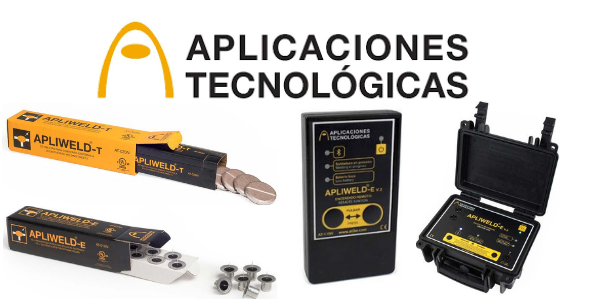
-
uploaded by Chris Dodds - Thorne & Derrick Sales & Marketing Manager
Exothermic Welding
Today, Thorne & Derrick welcomed Jason Leatherland (UK Manager at Aplicaciones Tecnológicas (AT3W) Lightning Protection & Earthing) to their UK office to learn more about their innovative Exothermic Welding System – Apliweld Secure+ is the safest + most efficient system for establishing Exothermically Welded Connections on substation earthing projects in the UK DNO, Power Transmission & Distribution and ICP sectors.
So What’s New?
The market-leading modern technology with remote electronic activation using Bluetooth replaces the conventional exothermic welding system dependent upon a manually applied spark using a Flint Gun for the welding and bonding connection of copper conductors including copper earth rods, cables and earth tapes.
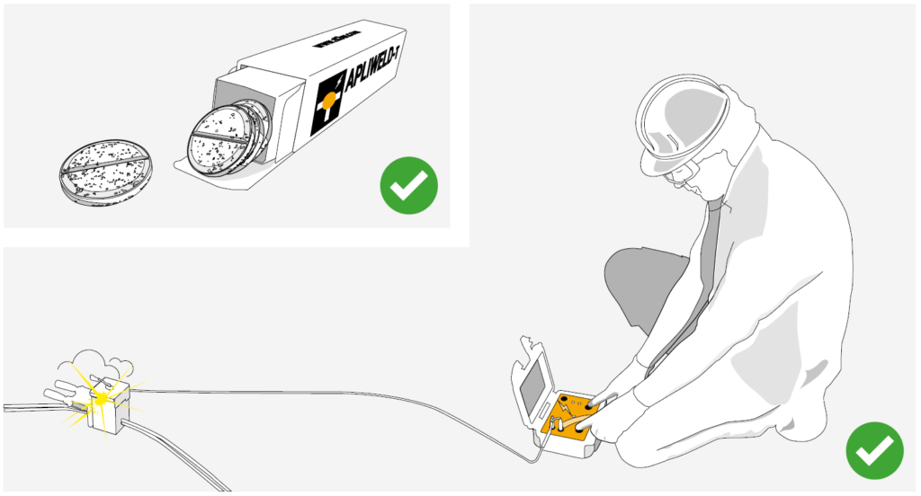
Apliweld Secure+ replaces traditional welding powders (and all of their size variations) with a welding tablet compound activated remotely, by up to a safe 5 metre distance, from the controlled explosion location – the electronic starter reduces risk of burns injuries and improves operational Health & Safety.
Apliweld Secure+ is accepted or in the approval process for use at National Grid, Northern Powergrid, Western Power Distribution, Scottish Power Energy Networks (SPEN) and Electricity North West (ENWL).
AT3W are a Spanish manufacturer and supplier of Earthing & Lightning Protection products and solutions – their unique selling point is their dedication to innovation and R&D within the industry along with their complete product/solution portfolio.
What is Exothermic Welding?
Apliweld exothermic welding is a process that achieves the molecular bonding among two or more metallic conductors by a chemical reaction. This molecular bonding improves mechanical, electrical and anti-corrosion properties compared with any mechanical or clamped connection. Apliweld exothermic welding is the most efficient method to achieve permanent, reliable and high conductivity connections for any LV MV HV substation or installation requiring an earthing system.
Secure Exothermic Welding At Safe Working Distance
APLIWELD Secure+ Exothermic Welding SYstem
Apliweld Secure+ is the most innovative, efficient and safest method for making electrical earthing connections with exothermic welding and comprises the of following components:
| APLIWELD Part Reference | Product Image | Product Description | Technical Characteristics | Benefits |
| APLIWELD-T Exothermic Welding Tablets |  |
Innovational tablet utilising only 2 sizes to produce all exothermic welded joints. Two references AT-020N, the most common one (valid for 90% of connections )and AT-021N larger size tablets, for use on larger joints. | • Reference: AT-020N • Tablet dimensions: ø 43 mm. • Units per pack: 20 tablets • Packaging dimen.: 52x52x220 mm. • Total weight: 900 gr.• Reference: AT-021N • Tablet dimensions: ø 55 mm. • Units per pack: 20 tablets • Packaging dimen.: 66x66x200 mm. • Total weight: 2.000 grams |
• Compact and easy to use • Reduces stock costs • Improves welding process times • Increases equipment life-time • Both electronic and powder starters can be employed |
| APLIWELD-E Electronic Starter |  |
Not flammable. Electronic starters only ignite through the power supplied by the ignition device. | • Reference: AT-010N • Dimensions: 26 mm. ø24 mm. • Units per pack: 10 • Packaging dimen.: 125x105x40 mm. • Total weight: 87 grams • Time of reaction: < 10 sec. • Material: not flammable |
• Its safety handle and storage features reduce labour risks • Safe & easy setup |
| APLIWELD®-E Electronic Ignition/Starter Device |
 |
Ignition box enables controlled and remote electronic ignition of exothermic welding connections in a quick and safe way. Includes: ignition unit (AT-096N), cable (AT-098N), 5 crocodile clips (AT-099N), battery charger and bag carrier. | • Reference: AT-100N • Power supply: • Lead acid battery 6V 7Ah • DC Voltage: 6V DC • Battery charge: 12-36V DC 500 mA • Battery life: more than 100 joints • Battery charging time: 10 hours • Dimensions: 216x180x102 mm • Weight: 2300 grams |
• Remote control ignition reduces labor risks. |
Apliweld Secure +
Benefits
- Eliminates the need for numerous variety of exothermic welding size powders
- Single welding compound reference for every welded earthing joint or connection
- Reduction of stock volume : cost ratio
- No shelf life and is non flammable
- Much safer to use – electronic ignition unit / Bluetooth starter as opposed to flint gun
- Minimises user error – every mould engraved with components/materials to be used
- Can be used in windy conditions (zero powder spillage)
- Highest possible ignition rates – less material failure
- Reduced wastage from cartons, cups etc
- Easy to use, reduces costs in labour and training
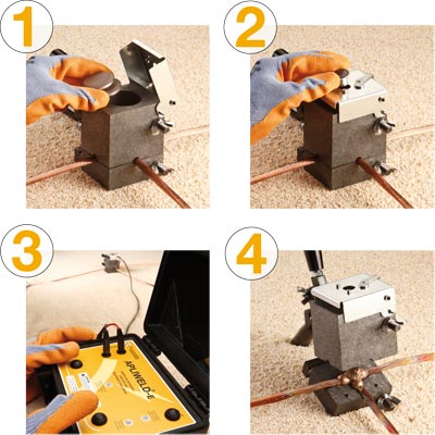
How to use Apliweld Secure+ Components

| AT3W Part Number | Product Image | Product Description | Stage | Process |
| APLIWELD-T |  |
Welding compound in tablets | 1. Insert the tablets APLIWELD-T |  |
| APLIWELD-E | 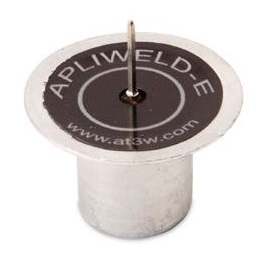 |
Electronic starter | 2. Place and connect the electronic starter APLIWELD-E |  |
| APLIWELD-E | 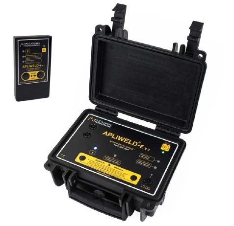 |
Electronic starting device | 3. Press both push-buttons on ignition device or Bluetooth remote at the same time |  |
| Exothermic Weld |  |
Graphite mould | 4. Remove the completed joint from the graphite mould |  |
Specific Exothermic Weld Mould Video
The following video shows the operating procedure for specific mould Apliweld Secure ensuring the process of exothermic welding is efficient.
Step 1 – Clean and remove any impurities from the mould or conductors
Step 2 – Heat the mould to 120°C before welding or when the mould is not hot enough
Step 3 – Fit the copper earth conductors into the mould and close the handle clamps
Step 4 – Set the proper number of tablets (see engraved on mould surface) in the crucible
Step 5 – Close the mould cover and place the electronic starter. Fix in position using lever
Step 6 – Open the Ignition Unit and connect the plugs. Connect the other side of the cable to the lateral part of the mould. Fix the clamp to the spike of the Electronic Starter
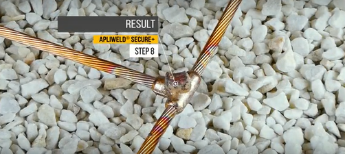
Step 7 – Keep away from the mould and switch on the Ignition Unit. Press both ignition buttons simultaneously until the exothermic welding process starts
Step 8 – Result is below image of an exothermically welded connection
Apliweld Secure – reliable electrical grounding, bonding and connection products for medium/high voltage substation earthing.

Contacts us NOW to arrange a DEMO or to discuss your Exothermic Welding requirements
Innovation, Reduction In Storage Costs & Increased Safety
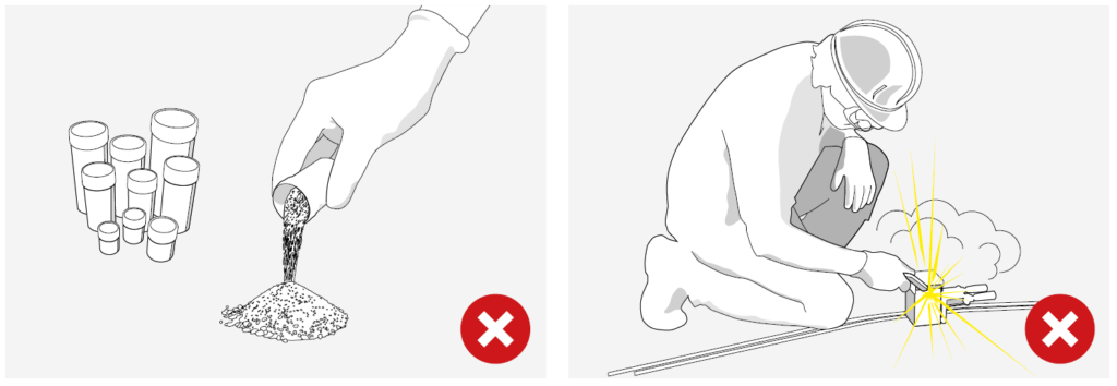
Traditionally, exothermic welding required the user to be provided with multiple cartridges with different welding powder weights for establishing various connections.
Once the conductors were inserted in the graphite mould the welding compound and the reactive powder (usually a flammable compound) were poured into the crucible. Then a flint gun applied manually to the starting powder at arm’s length produced a spark triggering the exothermic reaction.
Apliweld Secure+ utilises exothermic welding tablets NOT powders which are activated at safe working distance to suit all conductor combinations and configurations. The exothermically welded earthing connections are engineered to provide a permanent, molecular bond that will resist corrosion and loosening.
AT3W & Thorne & Derrick
Thorne & Derrick will be working with AT3W to introduce and develop specifications and business for the Apliweld Secure+ exothermic welding system.
Jason Leatherland comments, “having worked successfully together with Thorne & Derrick in the past, I was keen to demonstrate and discuss this product system with them as I knew they would be best suited to showcase the system, and in particular, its increased health and safety benefits, to the most relevant sectors in order to increase the users efficiency and reduce the potential of site accidents from exothermic welding.”
Jonny Hewitt (T&D UK Power Team) added, “working with the UK DNO’s and their preferred ICP’s we look forward to further developing relationships and presenting the exothermic welding system to existing and new clients. We will be working closely with AT3W to introduce the product to market and improve worker and site safety in the utility industry.”
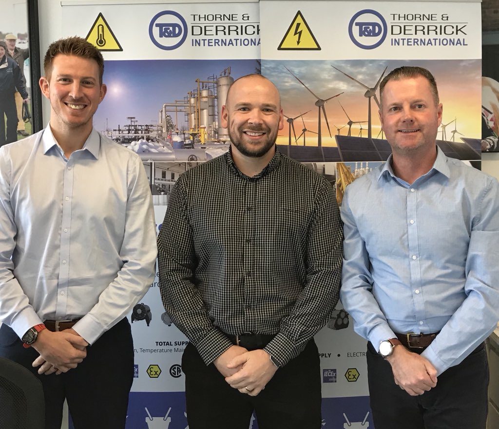
Pictured: Jonny Hewitt (T&D) with Jason Leatherland and Chris Dodds (T&D).
💡 HV Earthing & Lightning Protection Training Courses go to ➡ Online Training Resource provided by Ian Griffiths, Principal Engineer at GreyMatters. Ian is an Earthing & Lightning Consultant of 27 years, one of the top 1% UKAS accredited CDEGS consultants and professional advisor to international utility companies, data centre and infrastructure developers. See our Blog to learn more about GreyMatters and High Voltage Earthing.
LV MV HV Cable Accessories & Substation Electrical Equipment
Thorne & Derrick are Specialist Distributors of leading manufacturers of Cable Accessories, Substation Earthing, Jointing & Installation Equipment.
LV MV HV cable accessories from stock used to joint, terminate, connect, cleat and gland power cables to air and gas insulated substations, transformers, switchgear and overhead line networks.
LV 600/1000V ◊ MV 11kV 33kV ◊ HV 66kV 132kV
|
|
|
|
|
|
|
|
|
|
Cable Splicing At The Lazy Q Ranch
October 1st, 2018World-Class Cable Splicing Training
- Main Contributor – James Craven (Advisor at Quanta Services, Inc.)
- Uploaded – Chris Dodds (Thorne & Derrick Sales & Marketing Manager)
Training for Today to Meet Tomorrow’s Challenges
The following sequence of photographs provide a behind the scenes glimpse of Splicer Training at the Quanta Services Lazy Q Ranch, a state-of-the-art facility where the Art & Craft of Cable Splicing is alive and kicking. Nestled in the small town of La Grange where the Colorado River rolls and the Texan rattler hisses, the next generation of Cable Splicers are forged in the fires of their scorching hot pots of lead.
At the 2,200-acre campus Quanta employees receive hands-on instruction from passionate Master Trainers in a controlled environment focusing on safety, skill development and certifications. Quanta has even partnered with a local university to create a curriculum specific to their industry.
Setting Splicing Standards
Workmanship Rules OK!
Quanta do not set the standards – they raise the standards and lift the bar higher and then higher. There is no wriggle-room for the slightest splice error or even the most minor of measurement misdemeanour. Excellence is expected and why not?
James and the Lazy Q crew are changing the industry.
All practice splices and test splices are completely dissected as part of the curriculum – the test splices are actually cut into up to 10 or more pieces. The Splicer Assessor forensically checks the students submission – analysing tape application, scrutinizing measurements, checking connector and studying the lead seal and end wipes of the lead sleeve.
All images of cable splices and workmanship in this article were built by students.

RIP PILC?
Traditional cable Splicing skills are not dead or even dying out. PERIOD.
At least not Stateside.
Out on the range at Lazy Q, trainees are perfecting soldering, wiping and the complex intricacies of PILC Cable Splicing. Despite the 21st Century fashion for the grid to “Go Unleaded” as modern medium voltage power networks adopt polymeric cables there remains a demand for PILC Splicers with competent taping, soldering, wiping and compound pouring skills.
Yes, the prolific rise of Cold Shrink Splices has necessitated Jointer Training Centres to keep pace with cable manufacturing technology and introduce modules to cover the requirement to joint, splice and terminate MV cables using cold shrink as well as heat shrink accessories.
However, like it or not, with documented service lives of 60-80 years, PILC is here to stay.
Cable Splicing
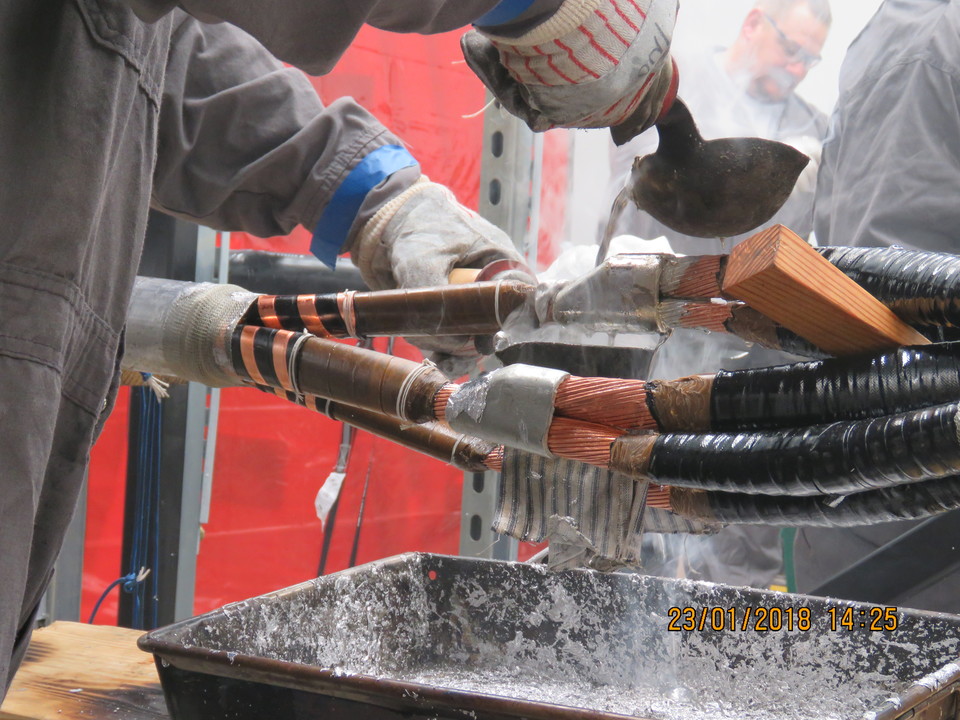
Student Splicers – here the trainees are cleaning down their lead pots in preparation for the 1/c 250 MCM lead splice. Using specialised cable splicing tools including soldering irons, melting pots, pouring ladles, tallow wiping cloths, lead ringers, compound kettles, stearine candles and paraffin dippers to perfect the wipe.
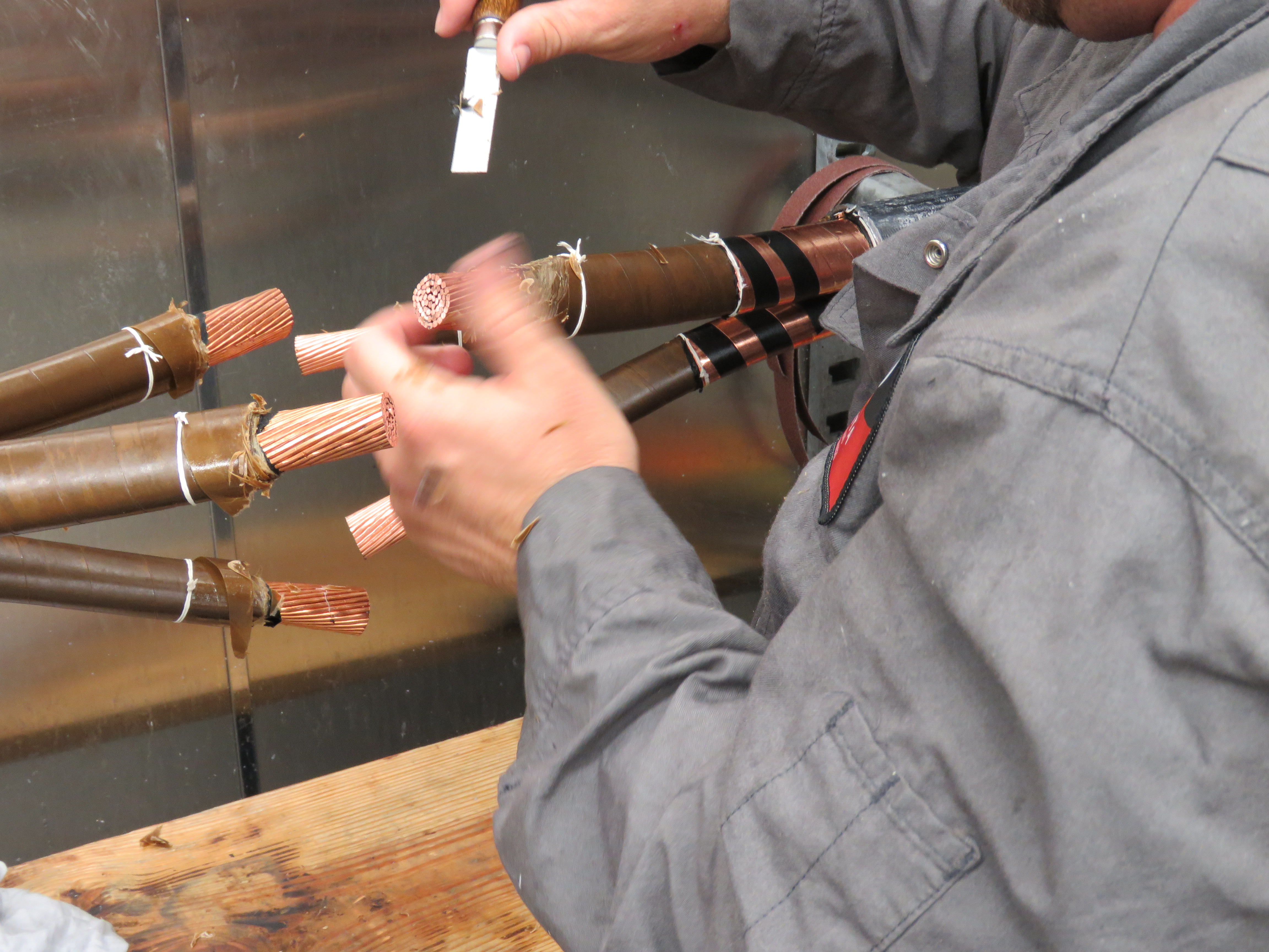
Pencilling Preparation – a student performs the cable pencilling in preparation for the 3 conductor sweat onto the practice cable splice. Safe knifework requires a steady hand, cool concentration and the manual dexterity of a surgeon. Because the power they’re supplying is electrifying and the Splicer must not lose control.
First, build the splice. Second, break the splice. Third, make the “Y” into a “V”.
With the insulators in place, the “Y” is now a “V”.

Image: John Perez (Quanta Underground Power Services)

Practice Makes Perfect – a practice cable splice by one of the student Splicers that was done in preparation of the test splice – 3/c 500 MCM PILC cable splice. Splice integrity is crucial – localised lead corrosion permitting moisture ingress into cable insulation through cracks in the wipe area being a main precipitation of cable failure.

Student practicing cable preparation and set up for sweating the connector.
PILC Splicing – here the student is pre-taping to fill in the insulation layer across the core connector.
Lead Splicers Night Light – a hot pot of lead that is being cleaned with Stearine. Stearine is a product used to cool the lead and to help remove impurities.
About Quanta Services
Quanta Services has the knowledge and expertise to handle a full spectrum of MV HV Power projects. From the most straightforward, single-component installation to the most complex, multi-state project, Quanta can handle the job safely, efficiently and cost-effectively.
For Quanta, safety is the core that all their values centre around. Quanta will find a solution for every customer, but they will also find the option that protects their people, their customers and their communities.

Safety – Core Principal of Quanta Services
Lazy Q Ranch – Training facility
John Colson, founder of Quanta Services opened a training facility known as Lazy Q Ranch in August 2015 where the industry workforce could be trained under the strictest safety measures.
The Lazy Q Ranch is a world class training facility situated on over 2,100 acres focusing on safety education, skill development and certifications.
Training is available for electric power lineman on cutting-edge technology for all transmission structure types and up to 345kV. This area is powered by its own substation, completely separate from the power provided for the Ranch. Quanta Energized Services oversees this portion of the training facility, bringing proprietary technology techniques to the workforce.
The oil and gas section houses pipelines in all major diameters, a flow loop and underground testing capabilities. The pipeline area was designed to be flexible and allow for various diameter pipes to be brought in for integrity testing and training, making this a custom-solution for training on a challenging project.
The telecommunications village features a small town with homes at various stages of construction. This enables development training at all milestones of a project.
The Lazy Q Ranch evolves with the industry and was designed to mirror Quanta’s growth. As Quanta Services expand their service capabilities, so will the training facility.
Currently Quanta are offering the following training courses:
- AUT Technology
- Barehand
- Crane Training
- Directional Drilling
- Fiber Splicing
- Fundamentals of Pipeline Inspection
- Hot Stick
- I&R
- Inside Build
- Lineman Training
- Micro-Trenching
- MT & UT Training & Certification
- Pipeline Data Analyst
- Q-Inline Prep for Field Based Inspection
- Robotic Arm
- Safety Accident Investigation Workshop
- Tool Testing
- Weights & Forces
- Work Procedure Training
Thorne & Derrick Specialist Electrical Distributor
LV ♦ MV ♦ HV
T&D distribute the most extensive range of LV, MV & HV Cable Jointing, Terminating, Installation & Cable Pulling Equipment – we service UK and international clients working on underground cables, overhead lines, substations and electrical construction at LV, 11kV, 33kV and EHV transmission and distribution voltages.
- Key Products: MV-HV Cable Joints & Terminations, Cable Cleats, Sealing Cable Ducts, Cable Transits, Underground Cable Protection, Cable Jointing Tools, Feeder Pillars, Cable Ducting, Earthing & Lightning Protection, Electrical Safety, Cable Glands, Arc Flash Protection & Fusegear.
- Distributors for: 3M, ABB, Alroc, Band-It, Catu, Cembre, Centriforce, CMP, Elastimold, Ellis Patents, Emtelle, Furse, Lucy Zodion, Nexans Euromold, Pfisterer, Polypipe, Prysmian, Roxtec.
LV – Low Voltage Cable Joints, Glands, Cleats, Lugs & Accessories (1000 Volts)
MV HV – Medium & High Voltage Cable Joints, Terminations & Connectors (11kV 33kV EHV)
Cable Laying – Underground Cable Covers, Ducting, Seals & Cable Pulling Equipment
More…
T&D’s Power Blog covers: LV MV HV & EHV Transmission & Distribution, Substations, Switchgear, Cable Jointing & Termination, Cable Fault & Repair, Underground Cables.
