

Blog
Cable Socks – Technical Guide for Safe Cable Pulling Using Cable Socks
March 21st, 2018
Thorne & Derrick | Cable Laying & Pulling Equipment Distributors | LV MV HV
-
Uploaded By Chris Dodds – Thorne & Derrick Sales & Marketing Manager
Cable socks, sometimes called cable stockings or cable grips provide an efficient method of supporting cables for pulling and laying into open-trench or duct – this includes LV Low Voltage, MV Medium Voltage or HV High Voltage cables.
The correctly sized cable sock can be used to pull in short lengths of cable by hand (e.g. fault repairs prior to jointing).
Cable socks are re-usable tools (subject to inspection before re-use) and are not confined to cable applications but basically can be used to support or pull any cylindrical object within their grip and load carrying capacity.
Standard cable socks are manufactured from high tensile galvanised and stainless steel wire rope or Kevlar.
A skilled, hand woven construction process, coupled with individual product inspection throughout manufacture ensures a high quality product for reliable and long lasting application.
UK DNO’s generally specify according to their Engineering Standards that all pilot and telephone, LV, 11kV, 20kV, 33kV, 66kV and 132kV cables shall normally be pulled in using a correctly sized cable socks which are securely fixed to the cable. More difficult pulls may require the use of a pulling eye attached directly to the cable conductors, which has been installed by the manufacturer – cable rollers shall always be used when pulling cables.
LV MV HV
Further information on the main ranges according to voltage application for underground power cable pulling or overhead line stringing can be found here:
- LV Low Voltage & MV Medium Voltage Cable Socks & Conductor Grips 33kV
- MV Medium Voltage Cable Socks & Conductor Grips 132kV
- HV High Voltage Cable Socks & Conductor Grips 275kV – 400kV
Cable Socks
WL & FOS
The Working Load (WL) of a cable sock depends on the Factor of Safety (FOS) applied to the Minimum Breaking Load.
For example, where the operational risk is considered to be normal, it is recommended that a FOS of 5 be applied, for high risk operations a FOS of at least 10 should be considered.
The Approximate Breaking Load stated on any certification, the recommended Factors of Safety, and any implied or stated fitness for purpose, are all only applicable when the cable socks are new and unused.
There are many factors that the person using the cable sock must take into consideration when trying to calculate a safe working load as it is impossible to guarantee a suitable safety factor when there are many variables which change from cable pulling application to application.
In addition, before using any cable sock, the user must carry out a full assessment of its suitability for the proposed application, and the level of operational risk involved, including taking account of:
- size of the cable sock, in relation to the size and shape of the gripped cable
- stability of the cables when gripped
- grip surface of the cable
- anticipated path of movement, including possible obstructions
- resistive force of the cables being pulled
- minimum-breaking load (MBL) of the cable sock
- condition of the cable sock
- suitability and compatibility of any cable pulling attachments used
- environment / operating conditions
When selecting the cable sock users must allow for a 20% variance in break loads and, if there is ‘twist’ in the cable, a suitable swivel link must be used.
When the correct cable sock is selected, cable installation through cable ducts, conduits and trenches is made considerably easier. The cable sock adds little to the overall diameter of the cable and ‘free passage’ is normally available through sheave blocks and pipes.
Cable socks can often be used on a ‘new for old’ cable replacement by applying two grips on a ‘back-to-back’ basis with a solid link or swivel in between grips, allowing the old cable to be used to pull through the new replacement.
Swivel links can be used to allow for reduced torque build-up induced by the cable pulling equipment and inherent lay in the cables themselves, whether LV, MV, HV or EHV. Lace up cable socks can be applied anywhere along the cable length, preventing overloading of the cable.
To prevent winched cable pulls exceeding the maximum tension force of the cables, a cable sock fitted with a swivel can be used to connect the bond to the cable and a dynamometer used to check that the maximum pulling tension for the cable is not exceeded.
When pulling cables by mechanical cable winch, the load-limiting device must be used to ensure that the pulling tension applied to the cable does not exceed the manufacturers specified maximum permissible tensions. The pulling of cables by direct and unmonitored mechanical means (e.g. hitched to a vehicle, Land rover winch) is not permitted.
Several UK DNO’s including Northern Powergrid, specify in their Policy for the Installation of Distribution Power Cables that cable pulling by winch shall only be carried out where there is a serviceable and accurate dynamometer calibrated in kgs.

Press Release | Thorne & Derrick Appointed Approved Stockist for UK Leading Cable Pulling Equipment Manufacturer
Cable Socks – Typical Applications
- Power cable pulling – LV MV HV
- Overhead house service cables
- Portable tool supply cables
- Portable compressed air lines
- Conduit risers
- Moveable hydraulic hoses
- Cable strain relief
- Oil support cables
- Marine applications
- “Guy rope” adjusters
- Fibre optic cable applications
Pulling Overhead Power Line Conductors Using Cable Socks
According to the Ericsson Universal Cable Handbook the most critical moment in the pulling out operation is when the cable end and cable sock passes through the line roller or suspension clamp. To make the pulling out easier the cable end should be “sectioned down” at the end before the cable sock is applied.
Between 150 – 200 mm/core is enough, see figure below.

This will make the end smoother and more flexible when it passes the cable pulling devices.
If a cable sock of Kevlar is used this is more important as it is soft and does not form a natural cone the same as a galvanised steel cable sock. The cores can also be cut with a knife to avoid sharp edges which will simplify the pulling even more.
Type of Cable Socks
Single Eye Socks – available in single or double weave.
Double Eye Socks – standard support sock, with double eye. Available in single or double weave.
Lace Up Socks – cable sock for fitting at points along the length of a cable.
Open Ended Socks – socks designed to enable two cables, hoses or ropes to be connected for pulling or supporting purposes.
Single Eye Socks (Triple Weave) – high strength cable socks with heavy duty shoulders, for stringing or pulling-in non-insulated conductors on long, high voltage transmission lines, or other high load applications.
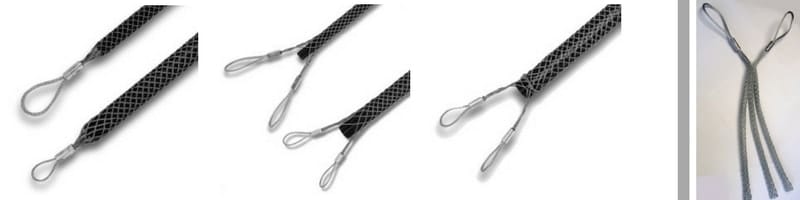
Single Eye | Double Eye | Lace Up | 11kV 33kV Triplex Cable Socks
Note : Cable socks must not to be used as primary lifting devices.
More Cable Pulling Blogs
- Cable Laying & Pulling – Installing LV-HV Cables Into Trench
- Cable Laying & Pulling – Installing LV-HV Cables Into Duct
- Cable Pulling Equipment – A Cable Laying, Duct & Installation Guide From SSE
- Cable Pulling Equipment – A Cable Duct Laying Guide From BT Openreach

Cable Pulling & Cable Laying Equipment Suppliers & Distributors
Thorne & Derrick International distribute the most extensive range of Cable Pulling & Cable Laying Equipment to enable the installation of low, medium and high voltage power cables into underground trench or duct – products also supplied for fibre optic blowing, subsea trenching, offshore umbilical installations and pulling armoured cables onto cable tray.
Contact us for 3M Electrical, ABB, Alroc, AN Wallis, CATU Electrical, Cembre, Centriforce, CMP, CSD, Elastimold, Ellis Patents, Emtelle, Euromold, Filoform, Furse, Lucy Electric & Zodion, Nexans, Pfisterer, Polypipe, Prysmian, Roxtec, Sicame, WT Henley.
Cable Blowers | Cable Lubricant | Duct Rods | Cable Socks | Cable Jacks | Cable Rollers | Cable Protection Covers MV HV | Cable Joints MV HV | Duct Sealing

Stainless Steel Cable Cleats – Preventing Galvanic Corrosion Of Cable Fixings
March 20th, 2018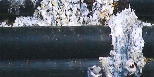
-
Uploaded By Chris Dodds – Thorne & Derrick Sales & Marketing Manager
Cable Cleats
In the following article we provide an evidence based specification case for stainless steel cable cleats where levels of atmospheric corrosion preclude use of other cable fixing materials.
One of the most important issues to consider when specifying cable cleats is the risk of material corrosion – not just as a result of the installation environment, but also from other metals which the cable cleat is in contact with.
Galvanic corrosion occurs when dissimilar metals are placed in contact with each other in the presence of an electrolyte. There are two factors that affect the rate of galvanic corrosion, the first is the distance between the two metals in the galvanic series.
The further apart the two metals are in the galvanic series, the greater the risk of galvanic corrosion – with the metal higher up the list (more anodic) being the one whose rate of corrosion is accelerated.
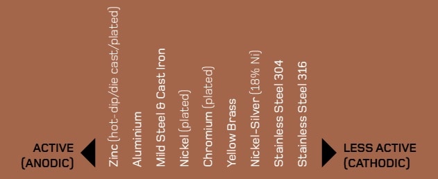
Galvanic Series
The second factor to consider is the relative surface areas of the different metals.
If the more anodic (higher up the list) metal has a smaller surface area than the metal it is in contact with, the difference in surface area causes the rate of corrosion of the anodic metal to increase.
Conversely, if the more anodic metal has a much larger surface area than the cathodic metal, it may be sufficient for the effects of galvanic corrosion to be discounted. In terms of cable cleat selection, the surface area of the cleat is generally significantly smaller than the structure it is mounted on.
Therefore, if it is made from a metal that is more anodic than its support structure it will be susceptible to galvanic corrosion.
Conversely, if the cable cleat is more cathodic than its support structure, there is little risk of galvanic corrosion.
Using this criteria, if galvanised ladder is the support structure, and there are no other significant factors, it is safe to use stainless steel or aluminium cleats. However, if the support structure is stainless steel, separation should be provided if aluminium or galvanised cleats are used.
Galvanic corrosion is not easily predictable and can be influenced by the type of electrolytes present such as salt water or fresh water containing impurities. In general terms when guarding against galvanic corrosion, the safest course of action is to separate dissimilar metals with polymer separation washers.
This separation should be carried out between the cable cleat and its mounting surface and the cleat’s mounting fixing.
All Ellis cable cleat products constructed from dissimilar metal are designed in a way that completely avoids bimetallic contact. As a result of this you can be confident that cable cleats will have a service life measured in decades.

Emperor Cleats – stainless steel cable cleats for single or trefoil cleating of cables with highest levels of short-circuit protection. Max S/c Test Level 235kA | 225mm Cleat Spacings.
Stainless Steel Cable Cleats
All Ellis stainless steel cable cleats are produced from 316L austenitic stainless steel.
In general, cable cleats are manufactured from austenitic stainless steel due to its non-magnetic and corrosion resistant properties – the former ensuring the cable cleat will not induce eddy currents or localised heating of the LV-HV cable.
Austenitic stainless steel does become a little magnetic as a result of work hardening when processed. This magnetism can barely be detected with a magnet and so is not significant from an eddy current perspective.
304 austenitic stainless steel, often referred to as A2, is one of the most commonly used stainless steels. It has excellent corrosion resistant properties in most circumstances, although is susceptible in atmospheres where chlorides are present, making it unsuitable for use in coastal or marine environments.
316 austenitic stainless steel, often referred to as A4, contains Molybdenum, which provides resistance against chlorides. 316 is often referred to as marine grade stainless steel due to its suitability for use in coastal and offshore applications.
If unsure a simple chemical test can determine whether Molybdenum is present and so differentiate between 304 and 316 types of stainless steel.
There are many different types of stainless steel, but there are two principal variants when it comes to cable cleats. 304 and 316 stainless steel are available in low carbon variants, namely 304L and 316L. These variants are immune to sensitisation (grain boundary carbide precipitation).
Any cable cleat which is manufactured from stainless steel and includes welding in the manufacturing process should be made in a low carbon (L) variant.
Should you require any further assistance in the selection or specification of stainless steel cable cleats for LV Low Voltage, MV Medium Voltage or HV High Voltage cables please do not hesitate to contact us.

Vulcan Cleats – stainless steel cable cleats for single or trefoil cleating of cables with moderate levels of short-circuit protection. Max S/c Test Level 132kA | 300mm Cleat Spacings.
Cable Cleat Coatings
The corrosion resistance properties of stainless steel are a result of chromium, which reacts with oxygen and forms a self-healing impervious layer of chromium oxide on the surface of the steel.
In most circumstances the chromium oxide layer is extremely durable and helps in resisting galvanic corrosion. However, in certain installation locations, such as railway tunnels, the oxide layer can be continuously penetrated.
This occurs due to trains frequently applying their brakes, which releases mild steel dust into the atmosphere that then settles on the stainless steel. If moisture is present, then corrosion occurs at an exaggerated rate. In such circumstances, if regular washing is not feasible, use of aluminium as an alternative to stainless steel products and/or coating processes are strongly recommended.
Ellis Patents offers special coatings to suit specific cable installation environments – e.g. our London Underground Approved electrostatic plastic coatings.
Cable Cleat Fixings
Closure fixings on cable cleats are fundamental to the loop strength of the cable cleat and its short-circuit withstand capability.
All Ellis Patents 316L stainless steel cleats use 316 fixings, which are manufactured to a precise and specific tensile strength. Fixings are sourced directly from approved manufacturers and any fixing on any cleat is directly traceable back to the batch quality records at that manufacturer.
Galvanised Steel
Contracts often require a guarantee regarding the life expectancy of a cleat. If the installation is designed correctly and all other corrosion issues have been considered this is a relatively simple exercise for stainless steel products. With galvanized steel, life expectancy is determined by the thickness of the zinc coating.
The resistance of galvanizing to atmospheric corrosion depends on a protective film that forms on the surface of the zinc. When the newly coated steel is withdrawn from the galvanizing bath, the zinc has a clean, bright, shiny surface. With time a corrosion process occurs which produces a dull grey patina as the surface reacts with oxygen, water and carbon dioxide in the atmosphere.
This leads to the formation of a tough, stable, protective layer, which is tightly adherent to the zinc. As the corrosion process is continuous, the thickness of the zinc layer reduces over time and it is the speed of this reduction that is used to accurately predict the life span of the cable cleat.
Corrosion Rates for the UK
Permission to use the information relating to galvanising was granted by the Galvanizers Association for galvanised steel. If a galvanised steel cable cleat is specified for use in a zone 3 area then the corrosion rate is 1.5 microns (µm) per year.
If the contract for this specification states a required life expectancy of 40 years, then the initial galvanising thickness will need to be a minimum of 60 µm in order to meet the required longevity.
Zinc corrosion rates are represented by 5 categories indicated by the colour codes below:

Zinc Corrosion Rates

Corrosion Rates for the UK
Cable Cleats Blogs
- IEC 61914 – Cable Cleats & Short Circuit Protection Calculations
- Fire Resistance & Cable Cleats – Surviving Fire, Flame & Extreme Heat
- Cable Cleats – London Underground 1-085 Standard For Fire Safety Performance
LV, MV & HV Jointing, Earthing, Substation & Electrical Eqpt
Thorne & Derrick International are specialist distributors of LV, MV & HV Cable Installation, Jointing, Duct Sealing, Substation & Electrical Equipment – servicing UK and global businesses involved in cable installations, cable jointing, substation, overhead line and electrical construction at LV, 11kV, 33kV and EHV.
THORNE & DERRICK Product Categories: Duct Seals | Cable Cleats | Cable Glands | Electrical Safety | Arc Flash Protection | Cable Jointing Tools | Cable Pulling | Earthing | Feeder Pillars | Cable Joints LV | Joints & Terminations MV HV
Cable Cleats – London Underground 1-085 Standard For Fire Safety Performance Of Materials
March 19th, 2018
-
Uploaded By Chris Dodds – Thorne & Derrick Sales & Marketing Manager
Cable Cleats
Thorne & Derrick a leading specialist distributor of cable cleats provide some information pertaining to the London Underground 1-085 Standard For Fire Safety Performance Of Materials – the purpose of the document download below is to define the requirements for the fire safety of materials, in terms of flammability, smoke emission and toxic fume emission, installed on the London Underground (LU) network.
Thorne & Derrick are Main Distributors for Ellis Patents – several ranges of Ellis Patents cable cleats are currently featured on the London Underground (LUL) Intranet system used by specifiers and buyers working on LUL projects.
Non-metallic cable hangers are also available for the support, retention and suspension of rail cables within tunnels meeting the requirements of the 1-085 specification.
Independent testing confirms conformance to the 1-085 standard including toxicity, limited oxygen and smoke emission.
- Ellis Patents Alpha Cable Cleats – Aluminium Trefoil Cleats Product Register 360
- Ellis Patents Emperor Cable Cleats – Stainless Steel Single & Trefoil Cleats Product Register 362
- Ellis Patents Vulcan+ Cable Cleats – Stainless Steel Single & Trefoil Cleats Product Register 361
- Ellis Patents Phoenix Cable Cleats – Fire Rated & Resistant Cable Cleats Product Register 1661
- Ellis Patents Non-Metallic One Hole Cable Clamps – Product Register 363 364
- View the complete range of Ellis Cable Cleats

Cable Cleats | Ellis Patents Vulcan | Alpha | Phoenix | Flexi-Strap | Triplex Cable Cleats
London Underground 1-085
This standard specifies the requirements for materials installed in underground rail locations with regard to:
a) Flammability (including the risk of explosion)
b) Smoke emission
c) Toxic fume emission
➡ Should you require any assistance with the selection of cable cleats or cable accessories compliant with London Underground 1-085 Standard please do not hesitate to contact us.
Cable Cleats Blogs
- IEC 61914 – Cable Cleats & Short Circuit Protection Calculations
- Fire Resistance & Cable Cleats – Surviving Fire, Flame & Extreme Heat
- Stainless Steel Cable Cleats – Preventing Galvanic Corrosion Of Cable Fixings
LV, MV & HV Jointing, Earthing, Substation & Electrical Eqpt
Thorne & Derrick International are specialist distributors of LV, MV & HV Cable Installation, Jointing, Duct Sealing, Substation & Electrical Equipment – servicing UK and global businesses involved in cable installations, cable jointing, substation, overhead line and electrical construction at LV, 11kV, 33kV and EHV.
THORNE & DERRICK Product Categories: Duct Seals | Cable Cleats | Cable Glands | Electrical Safety | Arc Flash Protection | Cable Jointing Tools | Cable Pulling | Earthing | Feeder Pillars | Cable Joints LV | Joints & Terminations MV HV
Fire Resistance & Cable Cleats – Surviving Fire, Flame & Extreme Heat
March 16th, 2018
Cable Cleats – Undergoing Fire Resistant Testing
-
Uploaded By Chris Dodds – Thorne & Derrick Sales & Marketing Manager
Cable Cleats
There are currently no European or IEC standards for fire rated cable cleats or clamps, although there are requirements within other standards that can be followed to prevent unsuitable cable cleats being specified and installed.
The international standard IEC 61914 requires non-metallic and composite cleats to have adequate resistance to flame propagation only.
UL94, the standard for Safety of Flammability of Plastic Materials for Parts in Devices and Appliances, is a plastics flammability standard that classifies plastics according to how they burn in various orientations and thicknesses.
Adherence to its V-0 rating for polymer cable cleats should be demanded by specifiers.
For information UL94’s V-0 rating means that burning stops within 10 seconds on a vertical specimen; drips of particles allowed as long as they are not inflamed.
The use of the description LSF (Low Smoke & Fume) is common terminology with regard to polymers, but is misleading as it doesn’t relate to any published standard and so can be interpreted in a wide variety of ways.
To ensure complete assurance of performance in a fire, all Ellis Patents plastic cable cleat products have undergone testing at the Building Research Establishment (BRE) in line with the London Underground 1-085 Standard specification with regard to:
- Smoke emission
- Limited oxygen index
- Toxicity of fumes
The appropriate cleats are listed in the London Underground Approved Products Register.
Identification numbers are 360, 361,362, 363, 364, 365 and 1661.
A great deal of focus is placed on fire rated (FP) cables and their performance in fire, but very little attention is given to the cable fixings used to secure these cables.
Given that FP cable is typically rated for operation in temperatures ranging from 850°C to 950°C then the use of plastic cable cleats or clamps is clearly inappropriate.
Even aluminium only has a melting point of 660˚C, which means it would fail to support FP cables in a fire. To counteract this shortcoming, Ellis manufactures the Phoenix range of cable cleats for use with FP cables. Independently tested by Exova Warrington fire and BRE, all products in the Ellis Patents range are proven to perform to the same level as the FP cables ensuring continuous operation in the event of fire.
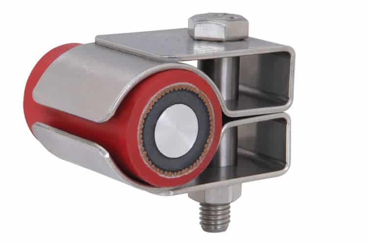
Ellis Patents Phoenix Cable Cleats – Fireproof & Fire Rated
Cable Cleats Blogs
- IEC 61914 – Cable Cleats & Short Circuit Protection Calculations
- Cable Cleats – London Underground 1-085 Standard For Fire Safety Performance
- Stainless Steel Cable Cleats – Preventing Galvanic Corrosion Of Cable Fixings
LV, MV & HV Jointing, Earthing, Substation & Electrical Eqpt
Thorne & Derrick International are specialist distributors of LV, MV & HV Cable Installation, Jointing, Duct Sealing, Substation & Electrical Equipment – servicing UK and global businesses involved in cable installations, cable jointing, substation, overhead line and electrical construction at LV, 11kV, 33kV and EHV.
THORNE & DERRICK Product Categories: Duct Seals | Cable Cleats | Cable Glands | Electrical Safety | Arc Flash Protection | Cable Jointing Tools | Cable Pulling | Earthing | Feeder Pillars | Cable Joints LV | Joints & Terminations MV HV
IEC 61914 – Cable Cleats & Short Circuit Protection Calculations
March 15th, 2018
IEC61914 – Calculating Short Circuit Forces To Specify Compliant Cable Cleats
-
Uploaded By Chris Dodds – Thorne & Derrick Sales & Marketing Manager
IEC 61914
Why Specify Cable Cleats?
“A cable cleat is a device designed to provide securing of cables when installed at intervals along the length of the cables”
taken from IEC 61914 Cable Cleats For Electrical Installations
Where the system peak fault current and the cable diameter are known, the formula above, excerpted from the international standard IEC 61914, can be used to calculate the forces between two conductors in the event of a 3 phase fault in order to specify the correct type of cable cleats.
Sub-standard or under-specified cable fixings including cable cleats and cable ties can cause catastrophic damage to infrastructure, power and life – for this no scientific formula exists to calculate the costs of power outage, plus the “nuisance factor”, downtime and consequential losses of reputation. Financially, that cost is immeasurable.
♦ Cable Ties
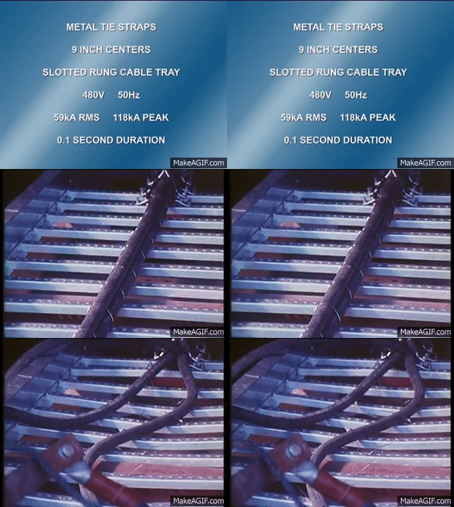
♦ Cable Cleats
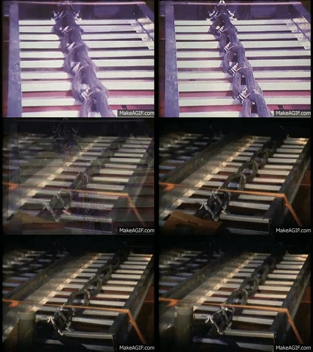
Cable cleats are designed and specified to withstand those forces exerted by the cable in the “axial” direction in most types of cable installation, including Flexible Cable Systems and Rigid Cable Systems.
i) Flexible Cable Systems – where the LV-HV cables are “snaked” either vertically or horizontally, the cables can expand and contract freely between the fixing points.
ii) Rigid Cable Systems – where the LV-HV cables are rigidly fixed and longitudinal thermo-mechanical force is withstood by the combination of the stiffness of the cable, the cable cleat, reaction force and the rigidity of the support structure.
IEC 61914:2009 specifies requirements and tests for cable cleats and intermediate restraints used for securing cable in electrical installations.
Cable cleats provide resistance to electromechanical forces where declared – this standard includes cable cleats that rely on mounting surfaces specified by the manufacturer for axial and/or lateral retention of cables.
IEC61914 applies to the management and safe retention of all cable configurations and voltages (LV Low Voltage | MV Medium Voltage | HV High Voltage) including bundled, quadrafoil (quad cleats) or single cables installed in 3 phase formation using trefoil cable cleats.
Electrical design engineers and specifiers specify power cables from which the maximum anticipated short circuit load can be calculated.
This data enables the calculation of the force between the cable conductors in a short-circuit situation – cable cleats installed to cable containment (whether cable tray, ladder or basket) are in turn specified at the correct spacing to contain potential short-circuit forces generated by the low/high voltage power cable system.
The aspects of construction and performance covered by IEC 61914 include:
- Material type – i.e. metallic, non-metallic or composite
- Minimum and maximum declared service temperatures
- Resistance to impact at the minimum declared operating temperature
- The ability of the cleat to withstand axial slippage forces
- Resistance to electro-mechanical forces – i.e. the ability of the cleat to withstand the forces between the cables in the event of a short-circuit
- Resistance to UV and corrosion
- Flame propagation
The strength of a cable cleat is often determined using a mechanical tensile test.
However, the results may be misleading because the force is applied in a slow and controlled manner, which does not replicate fault conditions.
In a short-circuit fault the forces are applied almost instantaneously and oscillate in every direction. Experience shows that a cleat that survives a mechanical tensile test at a given force will not necessarily survive a short-circuit test, even if forces are the same.
IEC 61914:2009 also provides formulae to enable the theoretical forces between conductors in the event of a short circuit to be calculated.
➡ Buy A Copy of IEC 61914 from the IEC Webstore.
Cleat Calculations
Where:
• Ft = maximum force on the cable conductor in Newton/metre (N/m)
• Ip² = peak short-circuit current in the kiloamp (kA)
• S = distance between the centrelines of the conductors in metres (m)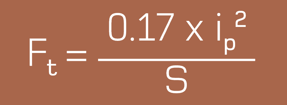
Once the Ft in N/m has been determined then the force for each potential cable cleat can be calculated.
For Example
Metric cable ladder typically has rungs at 300mm intervals, so cable cleat spacing is usually a multiple of this distance. So, Ft x 0.3 gives the force a cleat will see if spaced at 300mm, Ft x 0.6 for 600mm etc.
Ft x cable cleat spacing can then be compared to the maximum recommended mechanical loop strength of the cleat and then the cleat type and spacing can be selected.
Loop Strength of Cable Cleats
| Cable Type | Loop Strength (LS) |
| Alpha | 15,000N |
| Vulcan+, Protect and Standard Duty Flexi-strap | 36,000N |
| Emperor, Colossus and Heavy Duty Flexi-strap | 63,000N |
| Centaur Saddle and Clamps | 85,000N |
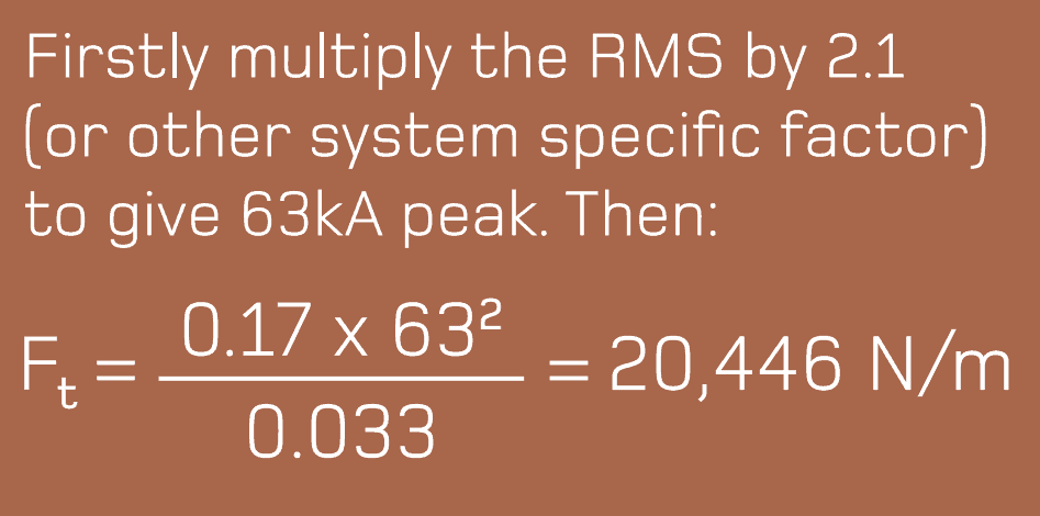
The formula uses peak current, however this is often unavailable with a Root Mean Square (RMS) value given instead – to calculate the peak current from the RMS, IEC 61914-1 Low Voltage switchgear and controlgear assemblies is commonly referred to, which uses the following multiples:
- 10 – 20kA = 2
21 – 50kA = 2.1
51kA = 2.2
Cable Cleat Calculations
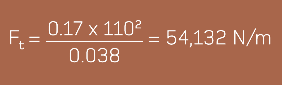
Example 1
Peak fault: 110kA
Installation: Cable Ladder
Cables in trefoil with an outside diameter of 38mm.
| Ft2 x Cleat Spacing | Required Loop Strength |
| 0.3 for 300mm | 16,240 N per cleat |
| 0.6 for 600mm | 32,480 N per cleat |
| 0.9 for 900mm | 48,718 N per cleat |
| 1.2 for 1200mm | 64,958 N per cleat |
This force per distance can then be compared to different cleat loop strengths to ascertain the appropriate cleat and spacing requirements for specification. In this example, the Ellis
recommendation was for Vulcan+ cleats (LS: 36,000) spaced every 600mm, or Emperor cleats (LS: 63,000) every 900mm.
The overall length of the LV-HV cable run will determine the total number of cable cleats required – the spacing requirements for cleats is subject to cable formation, diameter and short circuit rating but quantity of cable cleats is a factor of the cable circuit length.
Example 2
RMS fault: 30kA
Installation: Cable Ladder.
Cables in trefoil with an outside diameter of 33mm

Cable cleated in trefoil formation using stainless steel cable cleats
| Ft2 x Cable Cleat Spacing | Required Loop Strength |
| 0.3 for 300mm | 6,134 N per cleat |
| 0.6 for 600mm | 12,268 N per cleat |
| 0.9 for 900mm | 18,401 N per cleat |
| 1.2 for 1200mm | 24,535 N per cleat |
As with Example 1, force per distance can be compared to the cable cleat loop strengths and the appropriate cleat and spacing specified.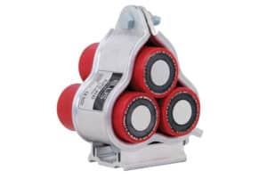
In this example, Alpha cleats (LS: 15,000) spaced every 600mm are the best option.
Before a cleat and spacing are finalised, two other factors should be considered irrespective of the short-circuit level.
1) It is strongly recommended that a system employs a fault rated cleat or restraint at a maximum spacing of 1500mm.
2) On bends and risers it is recommended that the maximum cleat spacing is 300mm.

Ellis Patents – The Cable Cleat Specialists. Standard & Customised.
IEC 61914 has provided a standardised method for conducting a short-circuit test and a definition of the criteria for a pass. It does though allow for a significant degree of latitude and so caution must be employed when interpreting results. Note should also be taken of the full report as opposed to just its headline page.
Short-Circuit Testing
There is a major difference between the short-circuit withstand requirements of a cable and the short-circuit withstand of a cable cleat.
The former is concerned with cable degradation as a result of temperature rise (thermal stress heating), while the latter is concerned with cable retention as a result of electromechanical forces.
Typical installation specifications that have been derived from the thermal withstand of the cable would require a short-circuit withstand of 63kA for 1 second or 40kA for 3 seconds.
A short-circuit test for a cable cleat does not consider this heating effect, and instead concentrates entirely on the destructive electro-mechanical forces at peak, followed by a short term decaying RMS.
The international standard IEC 61914 requires a short-circuit test duration of just 0.1 second. This equates to five complete cycles, by which time the true strength of a cable cleat will be known.
IEC61914 notes “a cable cleat is provided with a means of attachment to a mounting surface but does not rely on an unspecified mounting surface for the retention of the cables. Examples of mounting surfaces that may be specified are ladder, tray, strut or rail, wire and beam. Where declared, cable cleats provide resistances to electromechanical forces.”
Ellis Patents Cable Cleats
All Ellis Patents cable cleats have been tested for both axial and lateral loads – this ensures the cleats will support the weight of all cable voltages including LV Low Voltage, MV Mediujm Voltage or HV High Voltage.
➡ See the complete range of Ellis Patents Cable Cleats


♦ Further Reading
CIGRE Technical Brochure TB194 – Mechanical Forces in Large Conductor XLPE Cables
CPD Course
Learn More About Cable Cleats
Ellis Patents the world’s leading cable cleat manufacturer has taken its UK accredited Continuing Professional Development (CPD) course – Cable cleats: a device for short circuit protection– online so that it can be used by engineering professionals, wherever they are in the world, as part of their on-going programme of career development and learning.
Mod 1. Introduction – includes a brief history of standards plus the importance of detailed specification to ensure the correct cable cleats and fixings are chosen for the environmental conditions and applications.
Mod 2. Electrical Theory – learn more about short circuit faults, why they occur and their impact on cable systems. Also, how to calculate the forces involved and therefore how to ensure the correct strength of cable cleats are specified.
Mod 3. Materials – different cable applications require different solutions. Learn how sunshine, pollution and marine environments can cause problems if the wrong cable cleat materials are specified. How to avoid bimetallic issues and how to prevent corrosion. The importance of fire safety and low emissions is also studied.
Mod 4. Testing Cleats – some exciting video clips of when things go wrong, and of good engineering practice. Appreciate the international standards that apply to cable cleat design and the rigorous procedures involved.
Mod.5 Cable Cleat Applications – an overview of some cable cleating applications and interesting special cable fixing projects.


LV, MV & HV Jointing, Earthing, Substation & Electrical Eqpt
Thorne & Derrick International are specialist distributors of LV, MV & HV Cable Installation, Jointing, Duct Sealing, Substation & Electrical Equipment – servicing UK and global businesses involved in cable installations, cable jointing, substation, overhead line and electrical construction at LV, 11kV, 33kV and EHV.
THORNE & DERRICK Product Categories: Duct Seals | Cable Cleats | Cable Glands | Electrical Safety | Arc Flash Protection | Cable Jointing Tools | Cable Pulling | Earthing | Feeder Pillars | Cable Joints LV | Joints & Terminations MV HV


