

Blog
An Installation Guide For Feeder Pillars
August 22nd, 2018
Installation Of Retractable Type Feeder Pillars Manufactured by Lucy Zodion
-
uploaded by Chris Dodds - Thorne & Derrick Sales & Marketing Manager
Feeder Pillars
INTRODUCTION
This article covers the installation and maintenance of Pre-wired Feeder Pillars & Retractable Power Pillars as distributed by Thorne & Derrick and manufactured by Lucy Zodion.
This article is to provide assistance to the end user in the installation, maintenance and operation of their feeder pillars – it is not exhaustive and a suitably qualified person should be consulted if in any doubt. It is important to note that any modifications made to the pillars without authorisation by Lucy Zodion are outside the scope of this article.
Retractable Type Feeder Pillars
Lucy Zodion supply two types of retractable power supply feeder pillars namely ‘Castle’ and ‘Westminster’ types – these feeder pillars are part of the Lucy Fortress range of Low Voltage Electrical Distribution Equipment.
These feeder pillars mount flush to the top paving surface when not in use and are pulled up for use when LV power supply is required. Feeder pillars typically supply low voltage power sockets for supplying temporary power to events such as markets, outdoor events and broadcasting. Pillars are available in a variety of specifications, including single and three phase electrical connections and data sockets, as specified by the end user.
A downloadable specification form is available to initiate the electrical engineering design of all Lucy Zodion type feeder pillars.
♦ Electrical Regulations
This Blog written with the support of Lucy Zodion should be read in conjunction with BS 6423:2014 (this replaced BS 6423:1983), the Code of Practice for maintenance of LV electrical switchgear and control gear for electricity voltages up to and including 1000V/1kV.
All electrical work should be conducted in accordance with the Electricity at Work Regulations 1989.
All feeder pillar installations should be designed, tested and installed in accordance with the IET Wiring Regulations BS7671 Requirements for Electrical Installations – any other local regulations in force at the time should be observed.
Installing Feeder Pillars
Pre-wired Electrical Distribution Feeder Pillars
Prewired pillars can be mounted either on the supplied metal root, which is buried in the ground see Figure 1 below, or bolted directly to a concrete base.
Lucy Zodion do not specify the exact nature of installation as it is the customer’s duty to consult a suitably qualified civil engineer for feeder pillar installation.
The following procedure is for guidance only:
- Excavate a trench to the depth of the root section plus the depth of the solid base the unit will mount on, and approximately 30 cm greater than the width and depth of the feeder pillar
- Lay a solid base to the trench, for example paving slabs
- Place feeder pillar on to base and draw cabling into pillar
- Backfill trench with suitable gravel
- We advise capping of the gravel with concrete in the base of the feeder pillar and make good the surrounds with suitable material
➡ It is the customer responsibility to ensure the suitability of the site for the feeder pillar unit specified.

Figure 1 Pre-wired Feeder Pillars – Method of Installation
Retractable power pillars are mounted flush with the existing road/paving surface, and have recesses manufactured at a suitable depth to continue the existing surface material onto the folding
doors of the feeder pillar to leave a safe installation with low visual impact.
Figure 2 below is supplied for guidance only and a suitably qualified civil engineer should always be consulted to determine the exact method of installation.
It is crucial that the unit is equipped with suitable drainage. Lucy Zodion recommend using a 100mm drain pipe with positive drainage to the main sewer. While the low voltage installation is IP67 rated, incorrectly replaced caps and covers allow opportunity for ingress of water and long term exposure can permanently damage to internal components of the feeder pillar.

Figure 2 Westminster Retractable Feeder Pillar – Method of Installation
Westminster Retractable feeder pillars are supplied with recess pockets of a suitable depth for the proposed infill material. This depth is specified at order. Infill material must be installed flush with the surface and around the lock cover and hinges. Some means is necessary to hold the material in place when the feeder pillar is in the vertical, raised position, e.g. solvented grab adhesive.

Figure 3 – Top Cover Of Westminster Retractable Feeder Pillar
Electrical Requirements
Pre-wired feeder pillars and retractable power pillars are supplied pre-wired and tested at Lucy Zodion’s factory. A copy of the test documentation, along with a schematic drawing of the Lucy Zodion supplied equipment, is supplied with the pillar. It is assumed that electrical installation is conducted by a suitably qualified and skilled person and the following information is for general guidance only.
➡ A full test in accordance with BS7671 must be carried out, and a certificate issued, by the installing party after installation on site.
Electrical Connection Of The Feeder Pillar
Feeder pillars are typically supplied with a single phase 230V or 3 phase 415V electrical power supply feed from either a DNO/REC or private supply. Suitable space has been left for installation of DNO/REC cut-out if specified; this can be verified with reference to the drawings supplied with the pillar.
DNO/REC power supplies are connected to the pre-installed equipment using the pre-wired double insulated tails from the main switch disconnect.
Private supply feeder pillars are wired into the equipment using the customer’s cable.
The cable may be wired and connected directly into the main switch disconnect, wired through a cable spreader chamber or wired into a terminal enclosure depending on the size of the incoming cable.
The provision for terminating incoming cable can be determined from the drawings that accompany the feeder pillar or identification of the parts on the pillar.

Lucy Zodion Westminster Feeder Pillars – In Ground Power Distribution Pillars | LV Power Distribution
Lucy Westminster Feeder Pillar Features
- Modified lift assist at first lid to improve longevity and operation ease
- Lift assist added to tower for smoother and safer set-up
- Improved locking system for vibration resistance
- Enhanced Tower latching with slam lock means quick and easy access

Lucy Westminster – Versatile, Discreet , Robust & Safe Power Pillars
Cable Terminations
As feeder pillars are often located remotely from the electrical equipment they supply the outgoing cable sizes often have a large cross-sectional-area for the current rating and cannot be terminated directly into the pillar equipment.
For large outgoing CSA cable sizes suitable cable termination equipment, terminal studs or blocks, are supplied pre-wired into a terminal box.
Incoming and outgoing cables should be wired into these terminals, if supplied, to avoid overcrowding on the main distribution board or where equipment is unable to accept cables of the size specified.
Smaller cable sizes can be wired directly onto the equipment as appropriate.
Suitable space has been left for the cable glanding of outgoing unarmoured or armoured cables, in the form of cable gland plates on the distribution or terminal enclosure, a cable spreader chamber or a horizontal length of galvanised trunking.
Earthing
A dedicated ten way, brass earth block with an adjacent label reading ‘SAFETY ELECTRICAL CONNECTION, DO NOT REMOVE’, is supplied in a prominent and easily assessable location on the feeder pillar backboard. The pillar and all accessible metal parts within the pillar and all CPC earth in pre-wired equipment are equipotentially bonded to the earth block.
It is essential that pillars are connected to a suitable earth upon installation.
Electrical Connection Of The Feeder Pillars
Retractable feeder pillars are supplied with a terminal enclosure mounted in the fixed base of the unit and attached to the outgoing circuits via a pre-installed flexible cable. Once cable terminals have been connected and appropriate tests conducted the supplied Magic Gel should be used.
Magic Gel Instructions:
- Empty both sachets into a suitable mixing container
- Mix thoroughly; pour into the terminal box to above the height of the terminals
- The Magic gel starts to cure in about 4 minutes and will fully cross-link in about 10 minutes depending on temperature
- The Magic gel can be broken up and removed should the installation require alteration
In all cases the installation must be connected to a suitable earth supply. The installer should check the earth loop impedance of the installation as this cannot be verified at the factory. Unsupported lengths of cable should be kept to a minimum.
Where there is more than one cable they shall be connected along their length at not more than 1 metre intervals.
Operation : Pre-wired Pillars
This section covers standard equipment often supplied pre-wired into Lucy Zodion pillars.
For special equipment not covered in this manual please contact Thorne & Derrick.
All pre-wired pillars are supplied with isolation devices which can be locked off.
It is essential that the supply is isolated before any covers are removed from enclosures. For work to be carried out on the incoming terminal board or switch disconnect it is necessary to isolate the supply coming into the feeder pillar.

Figure 4 Common Components of Pre-Wired Pillar
Switch Disconnect
Switch disconnect isolates the main incoming supply from the rest of the equipment in the feeder pillar.
Switch disconnects may be SP & N, TP & N, SP&SN or TP &S N as required by the customer.
In cases where a switched neutral is installed the live phases always cut out first when the switch is disconnected. All main isolators are capable of being locked off to allow safe working on the equipment.
It is essential to lock-off the device when working remotely from the pillar, for example double sided or double length feeder pillars, or equipment being supplied from the pillar.
Switch disconnects may be Fuse Combination Units which are suitable for making, breaking and isolation. The correct fuse for the device is installed prior to the unit leaving the Lucy Zodion factory.
Should the fuse require replacement it is essential that the correct rating of BS88 HRC fuse is fitted. The switch fuse can be locked-off to isolate the rest of the system from the incoming electrical power supply.
24 Hour Board
24 Hour Board provides a continuous, overload protected supply to electrical equipment within installation.
Usually this supply is the main panel board or fuse board of the installation.
In cases where the main board is group switched an auxiliary board will be supplied to supply 24 hour power the pillar equipment (e.g. light, heater and socket) and the group switch control equipment.
Socket outlets
Socket outlets for use by normal persons are supplied as standard via an overload protected, residual current device, e.g. RCBO, RCCD on the 24 Hour board. Periodic testing of this device is required via the test button on the unit.
Group Switch
Group switch controls a group of equipment, typically street lighting installations, via a control system, such as a photocell or timer. Be sure to isolate a group switch from the incomer on the 24 Hour board, as group switches are remotely controlled they can go live at any time.
Group switch control – the group switch can be controlled by a timer, photocell or an override. A typical installation with a group switch would control street lighting.
- Solar Time Clock – is pre-set in the factory for the final geographical location of the pillar. To override the time switch press and hold the two central buttons on the controller until the output condition of the unit changes in the display.
- Photocell – either one or two part, switches the group switch contactors when ambient light levels fall below pre-determined level. One part photocells have the sensor mounted on the side of the pillar as standard. Two part photocells allow the installer to install the sensor head remotely from the pillar, the terminal from the photocell are wired into the unit in the pre-mounted 125x125mm enclosure within the pillar.
- Override Switch – switches the contactors on for testing of outgoing circuits, or for functional switching of the load. The use of a timer in conjunction with a photocell allows the lighting to be illuminated when either light levels or time dictates
Residual Current Devices
Residual current devices all socket outlets are protected by a residual current device as well as suitable overload protection. It is the end users’ responsibility to ensure that all equipment connected to sockets within the feeder pillar is within the specified load and connected by a suitable cable as required by BS7671. All residual current devices should be tested periodically and at least every six months.
Surge Protection
Surge protection devices are installed, if specified, to suit the earth system indicated by the customer e.g. TT or TNS. Should the earth system change from the original specification it will be necessary to change the surge protection device. The surge protection device has an end of life indicator based on the amount of KVA diverted to earth. This requires periodic inspection. Should the device indicate an end of life condition the unit will need to be replaced by a competent person.
Operation Instructions
Raising and lowering: – the unit is unlocked using the supplied T key. The key is inserted and twisted through 90 degrees. The key is held in the lock and is used as a handle to pull the top cover open. The socket unit is raised using the handle on the top and locked into position using the two retractable lugs. The cover is subsequently lowered back into position.
The socket box is fitted with a tilt switch which switches on the supply to the unit as it is raised. The LED on the top of the box indicates that the power is connected. Plugs are connected into the sockets by rotating the cover anti-clockwise until it is released and able to swing up. The sockets are functionally switched using the toggle switch on the RCD.
➡ To maintain the IP rating of the unit all caps must be properly replaced on the sockets and the RCD cover fully tightened before the unit is lowered after use. Lowering is the reversal of opening.
Electrical Supply
Functional switching for sockets is provided by the isolation switch on the RCD. The transparent plastic cover provides ingress protection to the residual current devices. To access the switches rotate the knurled thumbwheels anti-clockwise until the bolt exit the hole and pull down the flap. Sockets are activated by pushing the switch into the up position.
Test the functioning of the residual current device at the time of switching. This is achieved by pressing the test button, upon which the power should instantly be cut and switch revert to the down position. It is essential that the transparent cover is closed while the pillar is in use in order to avoid possible contact between water and electrical parts.
Retractable power pillars are fitted with cenorm style outdoor sockets with a minimum ingress protection of IP67.
Generally sockets will be 16A or 32A Single phase or 3 Phase. Single phase sockets are identified by a blue body and three phase by a red body, current ratings are printed on
the labels on the socket cover. Sockets and plugs of different types are not interconnectable and only plugs that match the current and phase rating of the socket should be plugged into it.
To open socket covers, rotate the grey outer wheel quarter turn and hinge the cover upwards. Holding the cover up, plug the plug into the socket, with the tang pointing downwards. The cover should locate with the raised lug on the socket to ensure security of installation. Removing the plug is a reverse of the process and it is essential to ensure all covers are properly replaced before lowering the power pillar.

Figure 5 Westminster Socket Box
Inspection & maintenance
➡ Warning: Feeder pillars may contain accessible live parts even when the unit has been isolated. Equipment covers should only be removed by skilled and authorised personnel.
The following recommendations are for guidance only as the nature of the environment and the conditions of operation will have a significant influence on the maintenance schedule required.
General Maintenance Policy
This document describes the routine maintenance requirements of Lucy Zodion Pre-wired pillars and retractable power pillars. It is assumed throughout that necessary precautions to render the apparatus safe to work on have been undertaken by suitably qualified personnel.
Conditions of use will have a significant impact on the service intervals of the equipment and it is advised that when units are installed in adverse conditions such as coastal areas, areas of high pollution, very frequent switching of loads or areas accessible to the public, that the maintenance interval is reduced to ensure reliable and safe operation of the equipment.
Under normal conditions of service, Lucy Zodion Prewired Pillars and Retractable Power Pillars are intended to give years of trouble free service. The best way to ensure trouble free service of your product is to conduct regular visual inspections and report any defects to a suitably qualified person for maintenance. As the retractable pillar is located below ground level, it is recommended that the adjacent area is kept clean around the lock mechanism.
Safety Precautions
Only skilled and instructed persons may remove covers from enclosures within the pillars. In order to avoid live working, installations should be isolated from the supply prior to maintenance within enclosures. General good housekeeping techniques, including the regular removal of any foreign bodies that have fallen into the tub are recommended as part of the maintenance programme.
* Incorrect alignment with a suitable drainage point, or blockage to existing drainage pipework on retractable power pillars may cause the container to fill with water, therefore route cause for blockage should be remedied by technically competent persons.
Socket caps fitted as standard are designed for compliance to IP67 rating, when correctly aligned and fitted. Please note that the socket caps incorporate a recess on the reverse face and in the folded flat position condensation may form in this recess which is released when unscrewing the cap, for socket connection, this has no detrimental effect on safety or performance.

Feeder Pillars – Lucy Zodion Fortress
Service Schedule For Lucy Zodion Fortress Feeder Pillars
Should you require competitive pricing, delivery or any further technical support to enable to specification or purchase of feeder pillars please do not hesitate to contact us.
| Maintenance Period For Feeder Pillar | Operations | Who Should Perform |
| After each use | Ensure all caps are replaced properly on IP rated sockets. |
End -User |
| Close and lock units appropriately |
End -User | |
| At least every 6 months | Test Residual Current Devices |
End -User |
| Ensure locking mechanism is cleaned |
End -User | |
| Removal of any foreign bodies. |
End -User | |
| At least Annually | Visual inspection : Damage – internally and externally, Paintwork, Operation of internal light. |
End -User |
| Test operation of pillar heater and light |
End -User | |
| Lubrication of Pillar hinges band locks |
End -User | |
| Five Years | Exterior and accessible interior parts cleaned |
End -User |
| Enclosures opened for examination and lubrication |
Qualified and skilled personnel only |
|
| Surge protection end-oflife indicator, inspection. |
Qualified and skilled personnel only |
|
| Fifteen years | General Overhaul | Qualified and skilled personnel only |

THORNE & DERRICK SPECIALIST ELECTRICAL DISTRIBUTOR
LV ♦ MV ♦ HV
T&D distribute the most extensive range of LV, MV & HV Cable Jointing, Terminating, Pulling & Installation Equipment – we service UK and international clients working on underground cables, overhead lines, substations and electrical construction at LV, 11kV, 33kV and EHV transmission and distribution voltages.
- Key Products: MV-HV Cable Joints & Terminations, Cable Cleats, Duct Seals, Cable Transits, Underground Cable Protection, Cable Jointing Tools, Feeder Pillars, Cable Ducting, Earthing & Lightning Protection, Electrical Safety, Cable Glands, Arc Flash Clothing & Fusegear.
- Distributors for: 3M, ABB, Alroc, Band-It, Catu, Cembre, Centriforce, CMP, Elastimold, Ellis Patents, Emtelle, Furse, Lucy Zodion, Nexans Euromold, Pfisterer, Polypipe, Prysmian, Roxtec.

LV – Low Voltage Cable Joints, Glands, Cleats, Lugs & Accessories (1000 Volts)

MV HV – Medium & High Voltage Cable Joints, Terminations & Connectors (11kV 33kV EHV)

Cable Laying – Underground Cable Covers, Ducting, Seals & Cable Pulling Equipment

T&D, CATU Electrical Safety & Arc Flash Protection Specialists for SAP’s, Linesmen, Jointers & Electrical Engineers – Largest UK Stockist
BS7609 | Crimping Cables With Cembre Cable Lugs & Tools
August 9th, 2018
Cembre Cable Lugs & Tools
-
uploaded by Chris Dodds - Thorne & Derrick Sales & Marketing Manager
BS7609 Code Of Practice For Installing Uninsulated Connectors With Copper Or Aluminium Conductors
BS7609
The BS7609 code is a British Standard which sets out what is best practice for the installation and inspection of uninsulated compression and mechanical connectors for power cables with copper or aluminium conductors – this effectively ensures the compliance with recommended workmanship when crimping cables using cable lugs to avoid built-in points of future failure in cable joints, terminations and electrical connectors at LV MV HV.
Incorrectly installed or crimped cable lugs can lead to “hot-spots” and the dangerous burning out of electrical cables causing devastating power failures and in worst cases fire.
Under-crimped cable lugs installed with uncalibrated crimping tools will lead to loose electrical connections triggering a disastrous domino effect: resistance restricts the ability of the current to flow effectively and consistently through the electric cable.
Thermal build-up in cable systems due to poor workmanship or poor quality cable lugs will inevitably cause cable joint or termination failure.
This problem is prevalent and amplified where cable systems and lug terminations are subject to high levels of in-rush current for standby power generation systems.
Remember – LOOSE WIRES CAUSES FIRES
Observance of BS7609 by electrical engineers, cable jointers and substation workers safeguards the reputation of the installer, their company and the manufacturer of the cable lugs or connectors – in this post we are working with Cembre the leading Italian based and one of the largest European manufacturers of electrical compression connectors, cable lugs and related crimping tools.
What Is Cable Crimping?
Crimping is the method of attaching the metal terminal or cable lug (typically copper or aluminium) around an electrical conductor to provide an excellent electrical connection.
Using the correct tool such as a Cembre cable crimping tool the cable lug is effectively bonded or compressed to the electrical conductor of the cable using high compression forces generated by the crimping tool.
Cable lugs are often over-looked in the specification and performance of LV HV electrical distribution systems, however under-specified or incorrectly installed cable lugs are major contributors to switchgear failures and power outages. Although arguably the lowest cost component of a cable installation, whether LV, 11kV or 33kV, the actual cost of cable lug failure in terms of loss of power and reputation is immeasurable.
Hydraulic Tools v Battery Crimping Tools
| Crimping Tool Type | Tool Reference | Crimping Range | Crimping Force | Tools |
| Hydraulic | Cembre HT131-C | up to 400sqmm LV HV Cable Lugs | 230kN | 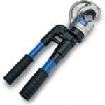 |
| Battery Operated | Cembre B500E | up to 630sqmm LV HV Cable Lugs | 63kN |  |
| Crimp Head + Foot Pump | Cembre ECW-H3D + PO7000 | up to 630sqmm LV HV Cable Lugs | 230kN |  |
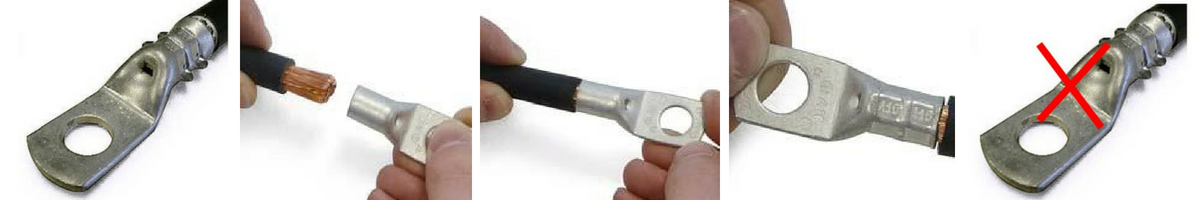
Crimping Cables – 6 Steps
Failure to observe these precautions can result in a compression connector, cable lug, cable joint or termination that fails in service.
- Choose a manufacturer providing crimp tooling, die set and crimp lugs matched to work together to give assured crimping performance. Avoid “cross-crimping” where a “dolly mixture” approach to the choice of lugs, tools and dies introduces a cocktail of often incompatible different manufacturers into the crimping process. Achieve a systemised approach i.e. crimp lugs + crimp tools + crimp dies = 1 brand.
- Each crimp lug should be marked with a reference on the barrel or palm – this shows that the cable lug selected is the correct size and type for the conductor. Refer to the die selector to select correct Cembre dies.
- Prepare the conductor by stripping the insulation back. The strip length should be equal to that of the cable lug barrel. Take care to avoid damaging the conductor strands – exposed cable strands should be cleaned to remove any remaining insulation from the LV MV HV cables.
- Fully insert the conductor into the barrel of the cable lug – check the cable conductor is fully inserted using the inspection hole provided.
- Using the manufacturers instructions, crimp the cable lug – paying careful attention to the positioning of the crimp die on the barrel of the lug. If multiple compressions are required pay attention to the sequence in which they are made.
- Use the following 6 points to check the completed crimp:
- Marking on the cable lug shows it is correct for the conductor type and size.
- The marking on the cable lug shows the correct crimping die set was used.
- No insulation is trapped in the cable lug barrel.
- Excess grease is removed from insulation and cable lug.
- If an inspection hole is provided, the conductor has been fully inserted.
- It is not over-compressed or under-compressed. Both of these can have a detrimental effect on the performance of the joint.Incorrect compression can cause excessive flash or burrs. If in any doubt, samples should be produced for test purposes.
In addition to the requirements of BS7609, Cembre advises the following when crimping cables – it is important that the crimped cable installation is not compromised by a poor choice of copper tube lug, or by the use of a ‘mismatched’ crimping system:
- Cembre supports the Approved Cables Initiative (ACI) Code of Practice to ensure that the conductor used is both third-party approved and appropriately marked.
- The cable lug should have an equal current carrying capacity to that of the conductor. Copper tube lugs designed and manufactured by Cembre achieve maximum electrical conductivity with minimum resistance by the use of high purity, electrolytic copper having a cross sectional area equivalent to that of the conductor.
- Beware cable lugs are manufactured from thin wall copper tube as they have the potential to cause elevated temperatures when the conductor is carrying high levels of current.
- Recommended procedures for conductor preparation and crimping Cembre copper tube lugs, including number, position and sequence where multiple compressions are required.
- Cembre copper tube lugs are also fully annealed after pressing to alleviate residual stresses within the palm area and ensure optimum mechanical and electrical performance at the connection interface.
- Ensure Cembre crimp tooling is certified as calibrated regularly and serviced correctly and all equipment, particularly die sets, is inspected for damage or wear and maintained in good condition.

Cembre Crimp Lug Correct Installation
Cable Crimping
Some best practise requirements:
- Approved cable conductor correctly prepared
- Conductor strip length = cable lug barrel length
- Manufacturer and size shown on crimp lug
- Cable lug and conductor have equal copper content
- Crimp tool optimises performance of dies
- Crimp dies matched to tool, lug type and size
- Correct number, position and quality of crimps
- Cable lug marked to check correct dies used
Choosing the correct Cembre die set:
- ALWAYS refer to the Cembre die selection chart. A die selection guide booklet is also included with every new Cembre crimp tool, whether hydraulic crimping tools or battery crimping tools.
The number and sequences of compressions per cable lug:
- The number and sequence of compressions shown in the die selection guides are specifically determined for Cembre lugs from the lug type and design, the force applied by Cembre crimp tooling and the bite width of the matched die set.
- ALWAYS apply the correct number of compressions as per the die selection guide in order to assure the performance of the joint after cable crimping.
- Apply each compression in the correct sequence to avoid distorting the cable lug.
Which Cable lug & die combination to use when crimping extra flexible conductors?
- Cembre copper tube lugs for extra flexible conductors 35sqmm to 185sqmm have the same cross sectional area of copper as standard Cembre A-M lugs for LV applications, but with a slightly wider inner diameter to more easily accommodate the fine strands.
- Above 185sqmm it may not be possible to use the correct size standard lug with an extra flexible conductor. For example, say a 240sqmm lug does not fit on a 240sqmm extra flexible conductor, it is acceptable and common practice to use the next larger size of lug, here 300sqmm.
- The lug MUST however be crimped with the die set appropriate to its size, 300sqmm, since using a 240sqmm die set will distort the cable lug and be detrimental to performance.
Which Cable lug & die combination to use when crimping compacted conductors?
- For low voltage applications use Cembre A-M Copper tube lugs. Matched crimp tooling and hexagonal die sets MUST be used.
- Always apply the rule that the cross sectional area of the lug should at least equal that of the conductor so, when using compacted conductor it is essential that the correct size lug be used, even if the fit appears ‘loose’ prior to crimping.
- The apparent ‘loose’ fit is due to the air between conductor strands having been ‘compacted out’ during manufacture, causing a slight reduction in the diameter of the conductor. The resulting gap between conductor and cable lug barrel wall is fully taken up during the crimping process.
- Do not be tempted to move down a lug size to obtain a tighter fit, as there will then be insufficient copper in the shoulder or palm of the cable lug. As an example, for 185sqmm compacted conductor use A37 lug, ME37-C die set and appropriate Cembre crimping tool.
Cembre
T&D are Main UK Stockists for the Cembre range of compression connectors (cable crimp lugs and splices) for all low and high voltage crimping applications of power, control and instrumentation cables with either copper or aluminium conductors.
Cembre copper, aluminium and bimetallic cable lugs and splices are designed for high voltage cable crimping applications including 3.3kV, 6.6kV, 11kV and up to 33kV. Cembre 2A HV cable lugs and splices are made from high purity copper, annealed and tin plated with extended barrels for reliable high voltage electrical connections.
Cembre electrical connectors are the market leading crimping system for reliability, consistency and peace of mind performance – specify Cembre to crimp, splice and terminate your vital high voltage electrical circuits.
A Quality Comparison – Cembre v Unbranded Cable Lugs
Both of the below copper cable lugs in picture 1 are specified by their respective manufacturers to crimp and terminate 400sqmm stranded copper cables – pictured right is the Cembre cable lug, note the CE Marking. CE marked cable lugs guarantee product compliance with EU safety, health and environmental requirements. Clearly the Cembre lug has increased barrel length and a thicker cable lug wall for an advanced standard of electrical connection with excellent conductivity due to high copper content – the thinner wall cable lug pictured alongside which is a imported and unbranded product is lighter weight and dimensionally smaller than Cembre brand lugs.
When terminating either armoured, unarmoured or braided cable types we recommend only to use branded type cable terminations such as Prysmian cable glands.
Quality – Cembre crimp lugs and splices are manufactured from electrolytic copper tube – the copper tube dimensions are designed to obtain the most efficient conductivity and mechanical strength to resist vibration and pull out. This includes electrical connectors for LV 600/1000V and MV HV cables operating at 11kV/33kV.
Strength – Cembre cable lugs are annealed to guarantee optimum ductility which is an absolute necessity for crimp connectors which must withstand the severe deformation arising when compressed by hydraulic crimp tools. In electrical installations subject to vibration, crimp terminals must perform a reliable connection – annealing avoids cracking or breaks between the cable lug palm and barrel. This applies especially to Marine & Shipboard cables in offshore installations subject to high levels of movement and mechanical stress.
Reliability – Cembre cable lugs feature an extended barrel design facilitating full insertion of the the copper conductor into the crimp lug – the cable lug barrel length has been designed to allow easy and accurate positioning of the dies during the crimping operation.
Note the distinctive quality differentials between the Cembre brand transformer lugs and unknown, unbranded type.

1. Cable Lugs – Low Voltage Single Hole 400sqmm.

2. Transformer Cable Lugs – Cembre Brand

3. Transformer Cable Lugs – Unbranded
Further Reading
- Crimping Aluminium Cables Using Cembre RHU131-C Presshead
- Selecting & Positioning Dies In Cembre ECW-H3D Presshead Tool
- Replacing Cembre Cable Cutting Tool Blades – Model TC055
- Ensuring Optimum Performance Of Cembre Crimping Tool – Model HT131-C
- Cembre B1350-CE v. B135-C Crimping Tools Performance Comparison

Thorne & Derrick – Stickists & Suppliers of MV HV Joints, Terminations & Connectors
Thorne & Derrick
T&D are Specialist Distributors of an extensive range of LV, MV & HV Jointing, Earthing, Substation & Electrical Eqpt – this includes 11kV/33kV/66kV cable joints, terminations and connectors for both UK DNO, private network applications and international cable specification and standards.
Contact our UK Power Team for competitive quotations, fast delivery from stock and technical support or training on all LV-HV products.
Key Product Categories: Duct Seals | Cable Cleats | Cable Glands | Electrical Safety | Arc Flash Protection | Cable Jointing Tools | Cable Pulling | Earthing | Feeder Pillars | Cable Joints LV | Joints & Terminations MV HV
Concentric & Split Concentric Cable Stripping Tools
August 8th, 2018
Alroc Tools – Cable Jointing Tools (LV MV HV)
-
uploaded by Chris Dodds - Thorne & Derrick Sales & Marketing Manager
Thorne & Derrick, Specialist Distributor of LV HV Jointing & Cable Installation Equipment are working with Alroc to improve the efficiency of cable preparation for Jointers working on LV MV HV electrical distribution systems.
The innovative Alroc DBT compact cable stripping tool is used by LV Jointers employed by NERS Accredited Independent Connection Providers (ICP’s) for the removal of the PVC outer cable sheath and primary insulation over the stranded copper or solid aluminium  conductor on BS7870 Concentric & Split Concentric cables.
These LV aluminium and copper cables are approved by UK Distribution Network Operators (DNOs) including Scottish Power Energy Networks (SPEN), Scottish & Southern Energy (SSE) and UK Power Network (UKPN).
Concentric and split concentric cables have been adopted as standard for use by DNOs to provide the final connection to residential properties. Additional cable functionality includes use for LV sub-main distribution and installation within high-rise buildings (LSZH Low Smoke Zero Halogen type) and street lighting systems.
The choice between Concentric and Split Concentric cable is determined by the supply type: TN-C-S supply for Concentric and TN-S supply for Split Concentric.
Concentric Cables
Concentric cables are used for power supplies with Protective Multiple Earthing (PME) systems, where a combined Protective Earth (PE) and Neutral (N) – together known as the PEN – connects the combined neutral-and-earth to real earth at multiple locations to reduce the risk of electric shock in the event of a broken PEN.
Split Concentric Cables
Split Concentric Cables are used when the power supply has separate PE & N conductors and are only combined as PEN near the power source. The Protective Earth and Neutral are not connected after the building entry point.
Jointers Tools
Alroc DTB cable end strippers enable the user to remove the outer sheath insulation of LV cable ranging from 16sqmm up to 150sqmm. The ruler engraved in the cable jointing tool sets the length of the XLPE insulation to be removed. The DTB cable end strippers are compact, light and heavy duty and are available for different cable sections – 16-25sqmm, 35-54.6sqmm and 70-150sqmm.
Alroc offer a range of low voltage cable preparation splicing and stripping tools suitable for use prior to cable joint and termination installation.

➡ Watch the following Video which demonstrates the ease and simplicity the Jointer can remove the cable sheath and insulation from the Concentric cables prior to installing the cable joints onto the distribution network.
Split Concentric & Concentric Cable Stripping Tool
♦ PDFs Courtesy & Property of Eland Cables

Alroc Tools are used and recommended by PFISTERER for MV HV cable preparation of cables prior to installation of their market-leading CONNEX plug terminations for connection to gas insulated switchgear and substations.
Thorne & Derrick
T&D are Specialist Distributors to UK Distribution Network Operators (DNO’s), NERS Registered Service Providers, ICP’s and HV Jointing Contractors of an extensive range of LV, MV & HV Jointing, Earthing, Substation & Electrical Eqpt – this includes 11kV/33kV/66kV cable joints, terminations and connectors for both DNO and private network applications.
Contact our UK Power Team for competitive quotations, fast delivery from stock and technical support or training on all LV-HV products.
Key Product Categories: Duct Seals | Insulated Tools | Cable Cleats | Cable Glands | Electrical Safety | Arc Flash Protection | Cable Jointing Tools | Cable Pulling | Earthing | Feeder Pillars | Cable Joints LV | Joints & Terminations MV HV
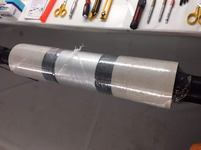
Pilot Cable Joint – Transition Joint PILC SWA To Multipair Jelly Filled Cable
July 26th, 2018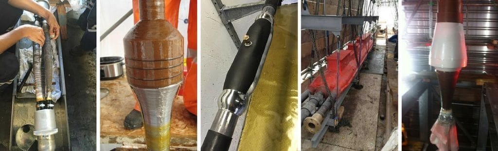
- Application: Transtion Joint PILC SWA To Multipair Jelly Filled Cable
- Cable Type: Pilot Cable Joint
- Cable Jointer: Darren Street Cable Jointer at D+R Jointing Services
Pilot Cable Joint
The pilot cable joint pictured below is twisted and tipped type.
The cable jointer had to improvise the installation due to the absence of a type tested manufactured cable joint which caters for this specific LV cable configuration – it would be usual to use a resin cable joint for standard straight jointing of pilot cables up to 100 pair.
Pictured jointed is a 30 core PILC armoured cable to 2 x 7 pair jelly filled steel wire armoured (SWA) telephone cables with PE insulation.
The Jointer used a small LV branch joint shell as a mould for resin which provided both mechanical and moisture protection. The connection of the cable cores was by soldering and then small lengths of heatshrink tubing were used to insulate the cable joint.
The Jointer established earth continuity of the lead sheath to wire armours on the plastic cable with constant force roll springs and tinned copper braid – to remove traces of petroleum jelly from the pilot cables 3M recommend use of their cable jointers and cleaning wipes.


Should you require any assistance with the selection or specification of pilot cable joints please do not hesitate to contact us.
Thorne & Derrick Specialist Electrical Distributor
LV ♦ MV ♦ HV
T&D distribute the most extensive range of LV, MV & HV Cable Jointing, Terminating, Installation & Cable Pulling Equipment – we service UK and international clients working on underground cables, overhead lines, substations and electrical construction at LV, 11kV, 33kV and EHV transmission and distribution voltages.
- Key Products: MV-HV Cable Joints & Terminations, Cable Cleats, Sealing Cable Ducts, Cable Transits, Underground Cable Protection, Cable Jointing Tools, Feeder Pillars, Cable Ducting, Earthing & Lightning Protection, Electrical Safety, Cable Glands, Arc Flash Protection & Fusegear.
- Distributors for: 3M, ABB, Alroc, Band-It, Catu, Cembre, Centriforce, CMP, Elastimold, Ellis Patents, Emtelle, Furse, Lucy Zodion, Nexans Euromold, Pfisterer, Polypipe, Prysmian, Roxtec.

LV – Low Voltage Cable Joints, Glands, Cleats, Lugs & Accessories (1000 Volts)

MV HV – Medium & High Voltage Cable Joints, Terminations & Connectors (11kV 33kV EHV)

Cable Laying – Underground Cable Covers, Ducting, Seals & Cable Pulling Equipment
More…
T&D’s Power Blog covers: LV MV HV & EHV Transmission & Distribution, Substations, Switchgear, Cable Jointing & Termination, Cable Fault & Repair, Underground Cables.
♦ See also – ABB 132kV Surge Arresters
➡ Visit Power Blog.

ABB NKT SMPGB Straight Cable Joint 420kV
July 26th, 2018
- Application: ABB NKT SMPGB Straight Joint 420kV 3 Piece
- Cable Joint: SMPGB Straight Joint 420kV 3 Piece
- Cable Jointer: Andy O’Malley (IBEW 258 EHV Cable Jointer / Cable Splicer – Allteck)
- Featured Manufacturer: ABB NKT
ABB NKT SMPGB Straight Joint
SMPGB straight joints manufactured by ABB are for jointing EHV XLPE and EPR insulated transmission cables with aluminium or copper conductors. The cable joints are suitable for jointing two cables that have different dimensions or screen sheath designs. The cable joint consists of a pre-moulded rubber tube with two pre-moulded rubber adapters, a bolt connector and a prefabricated PUR casted copper casing as outer protection for the joint.
In this instance it is recommended to use Alroc Tools for sheath, screen and insulation removal, however the correct cable jointing tool to use is dependent on the length of the chamfer and the EHV Joint product that is being installed.

Should you require any assistance with the selection or specification of cable joints or terminations please do not hesitate to contact us.
Thorne & Derrick Specialist Electrical Distributor
LV ♦ MV ♦ HV
T&D distribute the most extensive range of LV, MV & HV Cable Jointing, Terminating, Installation & Cable Pulling Equipment – we service UK and international clients working on underground cables, overhead lines, substations and electrical construction at LV, 11kV, 33kV and EHV transmission and distribution voltages.
- Key Products: MV-HV Cable Joints & Terminations, Cable Cleats, Duct Seals, Cable Transits, Underground Cable Protection, Cable Jointing Tools, Feeder Pillars, Cable Ducting, Earthing & Lightning Protection, Electrical Safety, Cable Glands, Arc Flash Protection & Fusegear.
- Distributors for: 3M, ABB, Alroc, Band-It, Catu, Cembre, Centriforce, CMP, Elastimold, Ellis Patents, Emtelle, Furse, Lucy Zodion, Nexans Euromold, Pfisterer, Polypipe, Prysmian, Roxtec.
♦ See also – ABB 132kV Surge Arresters
LV – Low Voltage Cable Joints, Glands, Cleats, Lugs & Accessories (1000 Volts)
MV HV – Medium & High Voltage Cable Joints, Terminations & Connectors (11kV 33kV EHV)
Cable Laying – Underground Cable Covers, Ducting, Seals & Cable Pulling Equipment
More…
T&D’s Power Blog covers: LV MV HV & EHV Transmission & Distribution, Substations, Switchgear, Cable Jointing & Termination, Cable Fault & Repair, Underground Cables.
➡ Visit Power Blog.
