

Cable Joints & Terminations HV
Circulating Currents | Screen Break MV Cable Joints for 33kV Cables
September 22nd, 2020“If you are encountering issues with circulating currents or standing voltages on extended circuit lengths of single core MV cables up to 33kV there is now a solution from Nexans to help control these unwanted and potentially dangerous issues by installing GTSIS.W screen break joints – these cable joints enable you to cross bond the screens of all three circuits in a safe manner that has been Tested and Certified to Cenelec HD 629.1 S2 & IEC 60502-4.
The screen break joints can help control circulating currents on medium voltage power systems and can accommodate MV cables up to 42kV using either compression or mechanical connectors – the joints do not eliminate circulating currents but they sufficiently reduce them to a safer and more manageable level (cable rating wise).
Contact Thorne & Derrick, the Main UK Distributor and Channel Partner for further information today.”
-
By David Rockall | Business Development Manager at Nexans Power Accessories (UK) Ltd
Screen Break Joints
Utilising heat shrink technology the GTSIS.W range of straight joints are compatible with unarmoured single core polymeric insulated cables with copper wire screens (35-1000sqmm) up to 33kV (42kV). Further Information here.
More from Nexans
- Nexans Euromold Screened Separable Connectors | Approval for Supply Within SSE’s Networks Business
- Nexans Euromold Connectors : EPDM Rubber Screened Separable Connectors For Medium Voltage Cables
- Facilitating Sensor Installation In Power Networks By Nexans MV Power Cable Accessories
- 66kV Connectors, Cables & Junctions Boxes – An Interview With Nexans
- Jointer Training Courses – 11kV 33kV 66kV Medium & High Voltage Jointer Competency Training
- 66kV Cable Jointer Training – A Question Of Competency Not Familiarisation
MV Cable Joints
Nexans NEW PRODUCT Launch

JST | Reliability & Safety at Reduced Cost – a modern generation of MV Heat Shrink Joint has been developed by Nexans for the UK utility and contracting industry – the primary application is for the jointing of 11kV BS7870 Triplex type medium voltage cables. The JTS cable jointing system now provides the most cost-competitive option to power contractors: the cable joints manufactured by Nexans, “The Global Expert in Cables & Cable Systems” are tested in accordance to CENELEC HD629.1.

LV, MV & HV Jointing, Earthing, Substation & Electrical Eqpt
Thorne & Derrick International are specialist distributors of LV, MV & HV Cable Installation, Jointing, Duct Sealing, Substation & Electrical Equipment – servicing UK and global businesses involved in cable installations, cable jointing, substation, overhead line and electrical construction at LV, 11kV, 33kV and EHV.
THORNE & DERRICK Product Categories: Duct Seals | Cable Cleats | Cable Glands | Electrical Safety | Arc Flash Protection | Cable Jointing Tools | Cable Pulling | Earthing | Feeder Pillars | Cable Joints LV | Joints & Terminations MV HV
Removal of Semi-Conducting Screens (Polymeric Cables)
September 7th, 2020
Cable Jointing Tools
Semi-Conducting Screens
STANDARD TECHNIQUE: CA2C/9
Relating to General Requirements for 11kV Cable Jointing
Extract from a Western Power Distribution Company Directive
The below guide explains the best way for the removal of semi-conducting screens.
Before commencing the level of PPE required for this operation shall be as the matrix given in General Requirement 3, your attention is drawn to the Use of Solvents General Requirement 1.
25.1 General
There are two types semi-conducting screens used on polymeric cables, fully bonded and easi-strip.
Virtually all polymeric cables used within WPD South have the easi-strip semiconducting screen.
While WPD Midlands have large amounts of easi-strip and fully bonded semi-conducting screens.
The method described here is for the removal of the easy-strip semi-conducting screen, which requires basic but effective cable jointer tooling and relative ease of removal to the installer.
Cable manufacturers currently supply two types of semi-conducting screen; both manufacturing methods can produce either easi-strip or fully bonded. With easi-strip semiconducting the material it’s important to have a compound such as ethylene vinyl acetate (EVA) which is strippable from the insulation.
In order for strippable screens to have sufficient tear strength during the removal from the insulation, it is necessary for the thickness to be approximately 1mm but the screen thickness can be thinner for harder materials. There are no such constraints with bonded screens and because the semiconducting materials are very expensive, thickness is kept to a minimum, 0.5mm being a typical figure.
The manufacturing methods are described as: –
- Monasil – identified by its smooth appearance.
- CCV (Continuous Catenary Vulcanising) – identified by its heavily ribbed appearance and characteristic acetophenone odour
- VCV (Vertical Catenary Vulcanising) – identified by its heavily ribbed appearance and characteristic acetophenone odour
25.2 Easi-strip Semi-conducting Screens
Note: – The method described below shall be THE ONLY APPROVED METHOD ADOPTED FOR USE within WPD for the removal of the easi-strip semi-conducting screens.
This phase of the jointing procedure must be undertaken with utmost care throughout this operation, failure to do so can be the cause or be a contributory factor in the failure of the joint or termination.
Cleanliness and attention to detail are vital, it is essential to avoid damaging the insulation at the semi-conducting screen termination, and any cuts or voids etc. will lead to the premature failure of the MV cable joint or termination.
2.1 Method of Removal
Refer to Drawing GR3D 6.25.1 whilst undertaking this General Requirement.
2.1.1 Mark the semi-conducting screen at its termination point with a white Chinagraph pencil.
2.1.2 Using PVC tape, apply (sticky side outermost for one complete turn) around the circumference of the cable at its termination point apply sufficient turns to provide a straight and square edge to guide the Abra file – Fig 1.
2.1.3 Using the Abra file with medium pressure, file evenly around the semi-conducting screen until the conductor insulation just shows – Fig 2.
Note: – The insulation must be seen continuously around the cable otherwise the semi-conducting screen may be lifted below its cable termination point.
2.1.4 Use a mirror to check the underside of the cable; there should be a smooth neat chamfer on what will be the remaining circumferential edge.
Note: – Where raggedness of the termination appears, run the Abra file with light pressure to remove high points; take care not to damage the insulation.
Ribbing of the semi-conducting screen may be removed by gently warming with a gas torch until the semi-conducting screen achieves a smooth surface.
2.1.5 Using the correct depth guarded knife (0.4mm for Prysmian 33kV & 0.6mm for Tratos 33kV cables) and starting just above the circumferential termination point make longitudinal scores spaced approximately 120° along the core length to its end – Fig 3.
Note: – Depending on cable size the three longitudinal scores may be reduced, two being the minimum otherwise undue stress is applied to the installers hands and cable.
Where there is extreme difficulty of drawing the depth guarded knife from the circumferential termination point to the cable end, and providing a cable tie is placed around the circumferential termination point to protect the shown insulation, the cable may be scored from the open end towards the circumferential termination point.
Utmost care must be given if using this alternative method, damage at the semiconducting screen termination point will result in failure.
2.1.6 Lift the semi-conducting screen at the open cable end and peel back the strips to completely remove – Fig 4.
2.1.7 Using aluminium oxide tape abrade the exposed insulation ensuring a smooth finish along its length and at the semi-conducting chamfer (any ribbing within the surface of the insulation must be abraded out to a smooth finish).
Note: – 400 grit is normally sufficient to provide this finish, but a start with 320 grit and finishing with 400 grit may be required.
2.1.8 Using an approved cable cleaner degreaser and white wipes, remove all traces of the semiconducting screen wiping from the cable end towards the termination point.
Note: – After each run change the wipe otherwise contact with semi-conducting material will come into contact with the insulation leaving possible tracking traces.
2.1.9 Finally remove the PVC tape applied in 2 and thoroughly check the insulation along its complete length ensuring its contamination free – Fig 5.

Removal of Semi-Conducting Screens (Polymeric Cables)
25.3 Fully Bonded Screens
This phase of the jointing procedure must be undertaken with utmost care throughout this operation, failure to do so can be the cause or be a contributory factor in the failure of the joint or termination.
Cleanliness and attention to detail are vital, it is essential to avoid damaging the insulation at the semi-conducting screen termination, and any cuts or voids etc. will lead to the premature failure of the joint or termination.
Note: – The stripping tool, Alroc CWB 18-60, which has been supplied to all the WPD Jointers on the 33kV Conversion course is designed for bonded screen cables ONLY and shall NOT BE USED on any EPR or XLPE EASI-STRIP CABLES.

Alroc CWB 18-60 Tool – Bonded Semiconductor Stripper | LV MV HV 11kV 33kV 66kV 132kV EHV Cable Jointing Tools
The bonded semi-con stripping tool issued to Midlands Jointers by Central Networks SHALL NOT be used on the 33kV system.
3.1 Method of Removal
Refer to Drawing GR3D 6.25.2 whilst undertaking this General Requirement.
The Alroc/Pfisterer tool works across the range of diameters over the semi-con screen of 18mm to 60mm.
Note: – THIS TOOL DOES NOT REQUIRE ANY SILICON GREASE TO OPERATE IN ADDITION THIS IS THE ONLY TOOL TO BE USED FOR BONDED SEMI-CON REMOVAL.
3.1.1 Ensure the cable is clean and straight.
3.1.2 Mark the semi-conducting screen at its termination point with a white Chinagraph pencil.
3.1.3 Set the tool stop to the required distance. Apply a roll spring to the white Chinagraph mark.
3.1.4 Close up the tool up using the large, red plastic knob, to provide a firm grip that will still allow the tool to rotate, as shown in GR3D 6.25.2.
3.1.5 Position the cutter at the front edge of the screen and set the depth of cut using the small metal knob as shown in GR3D 6.25.3. The adjustment is anticlockwise to increase the depth of cut, clockwise to decrease. If necessary, practice on a scrap piece of cable to obtain the correct depth setting. The ideal setup will have two thirds of the removed material to be the black semi-con and one third of the removed material being the translucent XLPE insulation.
3.1.6 With the correct depth set, now rotate the whole tool using the rear handle, in the direction of the arrow that is printed onto the body of the toool – as the tool is rotated it will move progressively down the cable, peeling the screen. Do not apply excess pressure. The selected depth setting should produce a clean, smooth cut free of black semi-conducting material.
3.1.7 When the required screen termination position is reached, the tool stop will come in contact with the roll spring thus providing clean screen edge and prevent the tool from moving down the cable. Continue to rotate the tool until a clean cut screen edge is produced. Open the tool and remove the tool on completion.
3.1.8 After the tool is removed, examine the surface of the insulation to ensure all semiconducting layer has been removed.
3.1.9 Using aluminium oxide tape, abrade the exposed insulation ensuring a smooth finish along its length and at the semi-conducting chamfer (any ribbing within the surface of the insulation must be abraded out to a smooth finish).
Note: – 400 grit is normally sufficient to provide this finish, but a start with 320 grit and finishing with 400 grit may be required.
3.1.10 Using the approved De-Solvit 1000FD degreaser and white wipes, remove all traces of the semi-conducting screen wiping from the cable end towards the termination point.
![]()
Jointers blog
Subscribe now to our POWER NEWSLETTER– a monthly email circulation packed with news, projects, videos, technical tips, training information, promotions, webinars, career opportunities and white papers.
Includes access to our popular JOINTERS BLOG with contributions from utility professionals, linesmen and cable jointers working on MV HV EHV cables and overhead lines typically at 11kV, 33kV, 66kV and up to 132kV.
15,000+ Subscribers. ➡ 
Online Monitoring Unit For Measuring 5 Individual Dissolved Gases & Moisture – Transfix DGA 500
September 7th, 2020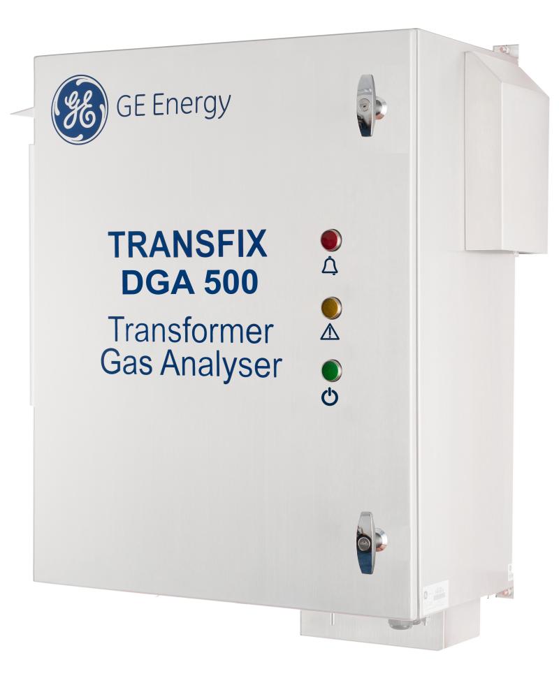
Transfix DGA 500 Transformer Gas Analyser
Online Monitoring
Transfix DGA 500 Transformer Gas Analyser
Guest Article | Fundamentals Ltd
Fundamentals exists to solve problems.
Their products and solutions have been improving the health and performance of the medium voltage and high voltage electrical grid for 25-years.
The Transfix DGA 500 transformer gas analyser is no exception.
Fundamentals Ltd is the only UK approved GE Monitoring & Diagnostics Channel Partner able to offer maintenance, repair, upgrade, installation and commissioning works for the Transfix DGA 500.
The Transfix DGA 500 is an online monitoring unit that measures five individual dissolved gases and moisture whilst providing both online monitoring and key exploratory diagnostics.
It provides dashboard and risk information for the transformer monitored and compares that transformer’s health with other similar assets to showcase its priority as part of the fleet management tool.
IEC Standard 60599
The Transfix DGA 500 enables the well-known Duval’s triangle DGA diagnostic described in Appendix B of IEC Standard 60599 and integrates seamlessly with Perception to provide not only dashboard and risk information for the transformer monitored but also to compare that transformer’s health with that of other similar assets and showcase its priority as part of the fleet management tool.
Online Monitoring Unit Key Benefits
- Five gases plus moisture (Hydrogen, Carbon Monoxide, Acetylene, Ethylene, Methane, and Moisture)
- Automated multi-gas plus moisture on-line monitoring
- Can specifically identify early arcing issues
- Ability to perform Duval’s triangle DGA diagnostic
- Easily replaceable with a full nine gas unit
- Communicates data to allow remote diagnostic
- No carrier or calibration consumable gases required
- Available with AC or AC/DC power supply
Transformer Gas Analyser Applications
Power Utilities
- Middle of the road solution for medium-criticality transformers
- Monitoring together with remote exploratory diagnostic
Industrial Plants
- Reduces the risk of process interruption due to power failure
- Minimizes costly production downtime
Should you require any further information, technical support and place an order for Transfix DGA 500 please do not hesitate to contact the Thorne & Derrick Sales Team.

THORNE & DERRICK are national distributors of LV, MV & HV Cable Installation, Jointing, Duct Sealing, Substation & Electrical Equipment – we service UK and global businesses involved in cable installations, cable jointing, substation earthing, overhead line and electrical construction at LV, 11kV, 33kV and EHV.
Since 1985, T&D have established an international reputation based on SERVICE | INTEGRITY | TRUST.
Contact us for 3M Electrical, ABB, Alroc, AN Wallis, CATU Electrical, Cembre, Centriforce, CMP, CSD, Elastimold, Ellis Patents, Emtelle, Euromold, Filoform , Furse, Lucy Electric & Zodion, Nexans, Pfisterer, Polypipe, Prysmian, Roxtec, Sicame, WT Henley.

Repairing Cables In Industrial & Hazardous Area Onshore & Offshore Locations
September 7th, 2020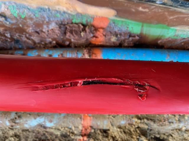
Repairing Damaged Cable Sheath
Repairing Cables
Guest Article | Carl Pike from Filoform UK
Industrial & Hazardous Area Onshore & Offshore Locations
Thorne & Derrick International are UK distributors for Filoform, a leading manufacturer of cable joints, duct seals and special resins for installation in the utilities, telecom, traffic, rail, fibre optic, street lighting and construction industries.
Have a damaged cable sheath or jacket?
Look no further – Filoform have innovated and made repairing a cable sheath simpler, stronger and hassle free.
Introducing
FiloSlim Cable Sheath Repair System
Whilst repairing damage to the outer sheath of a cable may seem like a formality, it is often subject to unforeseen conditions. Particularly if the cable is to be buried or subject to severe environmental elements.
Recognising these situations – FiloSlim Cable Sheath Repair Kit can repair them quick & easily with NO heat or special tools.
Repair Damaged Cable Sheaths
The FiloSlim Cable Repair kit has been designed to accommodate all types of cable sheath, and to withstand the rigors of many applications.
EPR, XLPE, PVC, PILC LV, MV & HV cable sheaths
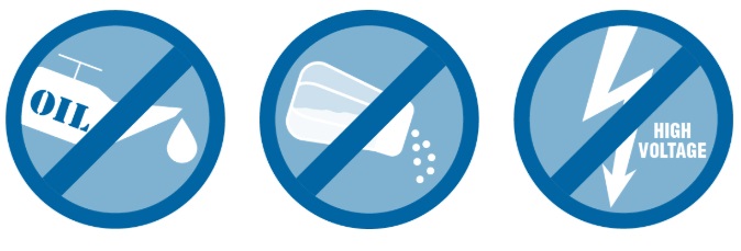
The unique Polyurethane Resin has been manufactured to offer protection in the harshest of conditions. Subsea, exposed to UV, wound onto cable drums and subject to attack by hydrocarbons within the petrochemical industry.
The FiloSlim Repair Kit is designed to offer a multi-functional, single solution, suitable to all markets. Onshore, Offshore, Hazardous Area, Direct Buried, Subsea: all remedied by a single product.
No heat source > total mechanical protection, suitable for low, medium and high voltage cables.
FiloSlim is a simple and effective method of repairing a damaged cable sheath and cable jacket. The flexibility of a quick and easy installation, coupled with the security of a long term seal against moisture, and the insurance of full mechanical protection.
Filoslim offers a welcome alternative to the historical heat shrink repair sleeves from TE Connectivity/Raychem CRSM, Hellermann RMS and DSG-Canusa CRDW.
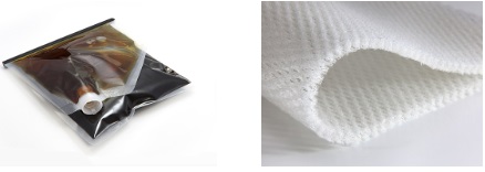
The totally enclosed mixing and pouring of the resin via the nozzle and non return valve.
Both the valve and outer tape wrap is removed easily at the end of the installation – offers a secure and safe method of work; even in the harshest of environments. From a pitching deck to a frozen landscape, Filoslim is quick, safe and easy to apply.
No specialist tools. NO HEAT source or naked flame.
One kit to suit all cable diameters up to 170mm, and the ability to offer bespoke solutions beyond that. Sheath repair made simple.
Questions & Answers
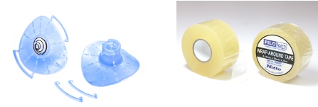
1, Can the blue injection valve be removed?
Yes, the tape and valve can be de-laminted after 1 hour of dispensing the resin.
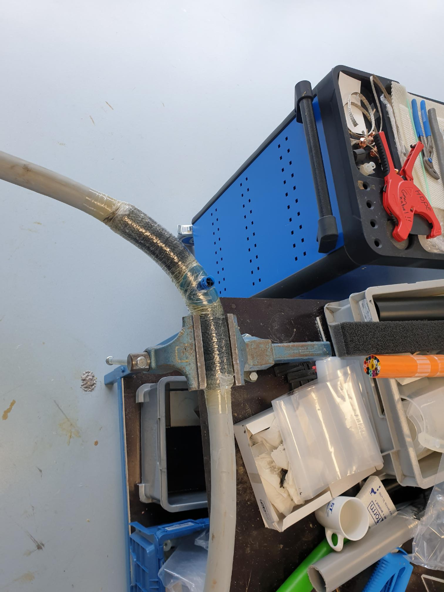
2, Is the resin flexible?
Yes, the resin will flex but does require a little force.(Example below shows a 95sqmm 4 core un-armoured cable)
3, Will the FiloSlim cable sheath system repair work if the damage is through to the conductor?
If we are talking about an LV cable, unarmoured, and with no damage to the conductor; we would say its fine. The conductor insulation being intact has retained the original integrity of the primary insulation within the cable;
However, if the insulation around the conductor has been damaged, we would propose stripping back a section of the cable and exposing the damaged area but not cutting the cable.
Over-taping this with self-amalgamating tape will restore the original integrity, and then the kit can be used from there.
filoslim Features:
- No heat source required
- No specialist tools
- Enclosed mixing and pouring
- Suitable for cables up to 170mm diameter as standard
- Suitable for use as a moisture seal
- Suitable for direct buried and vertical application cable repairs
- Suitable as an outer seal on EPR, XLPE, PVC and PILC LV and MV cable sheaths
- Void filling properties of the resin, negate the requirement for additional mastic tapes or gap fillers
- Seawater resistant repairs to cables
- Hydrocarbon resistant repairs to cables
- Kit contains all components required; including the resin, tape, nozzles and gloves
- Can be de-laminated (tape and blue injection valve can be removed, when cured)

LV Cable Joints (Low Voltage Cables)
Thorne & Derrick stock and distribute LV Joints in Cold Shrink, Heat Shrink or Resin Cast technologies – multicore and multi-pair cable joints are available for immediate backfill and energisation of Low Voltage power, control and instrumentation cables 600V/1000V 3.3kV.
Complete range of LV Cable Accessories ➡
Cable Breakouts | Cable Caps | Cable Lugs | Cable Cleats | Cable Trough | Cable Duct | Feeder Pillars | for 11kV/33kV/66kV networks see MV HV Joints & Terminations
Verifying MV Cable Sheath Integrity
August 18th, 2020Republished with the Kind Permission of Sam Soady |
Eccentricity Pty Ltd Director /HV Operator / Cable Jointer
Verifying MV Cable Sheath Integrity
As a cable jointer, most of the time I am called in to jobs at specific times during construction to complete high voltage cable terminations.
I usually only see the end stages of most projects, and the HV cables have already been installed by other contractors.
As the cable jointer and electrician certifying the cable installation, it is important to verify the cable has been installed appropriately. As the cables are generally buried direct underground or in conduit systems, it can be difficult to inspect the cable for physical damage that may have occurred during installation.
This is when a sheath integrity test should be performed. Eccentricity recommends testing the sheath integrity prior to installation (on the cable drum) and post installation (in the ground). This gives you a good baseline to compare to after the cable has been installed and whether damage has occurred during installation.
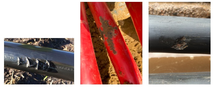
Potential hazards that can damage the MV cable sheath include:
- Binding machinery that wraps single core cables to tightly into trefoil
- Rocks / debris present in the underground trench
- Sharp edges along the route of installation
- Not using suitable aggregate material or sand when backfilling around cables
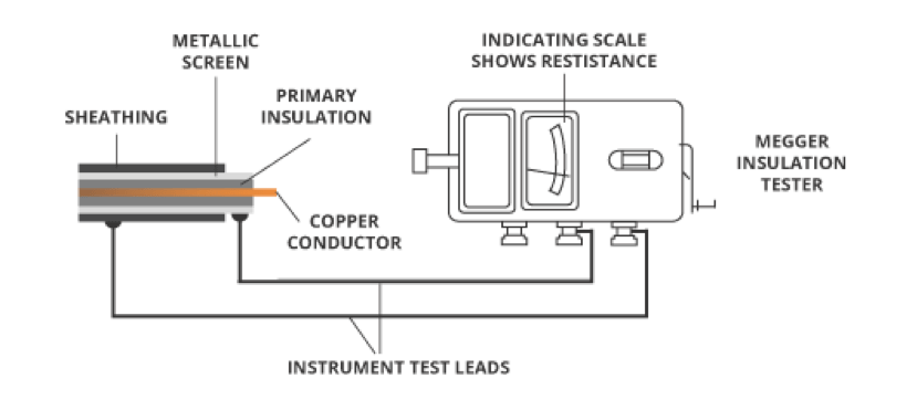
Image courtesy of Eland Cables
The sheath integrity test consists of a DC voltage injection on the screen wires of generally 1000V on MV cables to the general mass of earth. By proving the insulation resistance of the outer sheath is acceptable, it can be expected no damage to the outer sheath has occurred during installation.
Before Eccentricity completes any terminations for our clients, we complete this sheath integrity test to further ensure the baseline of the cable installed is adequate and the termination has not compromised the sheath in any way.
About Eccentricity
![]()
Eccentricity is a specialised Brisbane based company with a team of dual trade electricians and cable jointers. Our technicians are fully qualified to work on cables up to 66kV, including XLPE, PILC and EPR cables, backed by over a decade of industry experience.
With a modern and fully compliant fleet of industry vehicles, we are capable of accessing any high risk environment to perform works with a wide range of major MV HV cable jointing projects including, mining, oil, gas, renewable energy, and high voltage transmission networks.
Eccentricity has the capacity for small or large scale projects, providing reliability of power networks wherein client satisfaction is a top priority. We provide a high level of quality with all aspects of both installation and commissioning, ensuring we comply with all relevant regulations and legislative provisions.
Specialist Suppliers of High Voltage Electrical Equipment & Cable Accessories
Jointing, Earthing, Substation Electrical & Safety Equipment Distributors
Thorne & Derrick International are specialist distributors of LV, MV & HV Cable Installation, Jointing, Duct Sealing, Substation & Electrical Equipment – servicing UK and global businesses involved in cable installations, cable jointing, substation, overhead line and electrical construction at LV, 11kV, 33kV and EHV.
THORNE & DERRICK Product Categories: Duct Seals | Cable Cleats | Cable Glands | Electrical Safety | Arc Flash Protection | Cable Jointing Tools | Cable Pulling | Earthing | Feeder Pillars | Cable Joints LV | Joints & Terminations MV HV

Distributors for 3M Cold Shrink & Scotchcast | Nexans Euromold | Pfisterer Connex
