

Cable Joints & Terminations HV
BS7609 | Crimping Cables With Cembre Cable Lugs & Tools
August 9th, 2018
Cembre Cable Lugs & Tools
-
uploaded by Chris Dodds - Thorne & Derrick Sales & Marketing Manager
BS7609 Code Of Practice For Installing Uninsulated Connectors With Copper Or Aluminium Conductors
BS7609
The BS7609 code is a British Standard which sets out what is best practice for the installation and inspection of uninsulated compression and mechanical connectors for power cables with copper or aluminium conductors – this effectively ensures the compliance with recommended workmanship when crimping cables using cable lugs to avoid built-in points of future failure in cable joints, terminations and electrical connectors at LV MV HV.
Incorrectly installed or crimped cable lugs can lead to “hot-spots” and the dangerous burning out of electrical cables causing devastating power failures and in worst cases fire.
Under-crimped cable lugs installed with uncalibrated crimping tools will lead to loose electrical connections triggering a disastrous domino effect: resistance restricts the ability of the current to flow effectively and consistently through the electric cable.
Thermal build-up in cable systems due to poor workmanship or poor quality cable lugs will inevitably cause cable joint or termination failure.
This problem is prevalent and amplified where cable systems and lug terminations are subject to high levels of in-rush current for standby power generation systems.
Remember – LOOSE WIRES CAUSES FIRES
Observance of BS7609 by electrical engineers, cable jointers and substation workers safeguards the reputation of the installer, their company and the manufacturer of the cable lugs or connectors – in this post we are working with Cembre the leading Italian based and one of the largest European manufacturers of electrical compression connectors, cable lugs and related crimping tools.
What Is Cable Crimping?
Crimping is the method of attaching the metal terminal or cable lug (typically copper or aluminium) around an electrical conductor to provide an excellent electrical connection.
Using the correct tool such as a Cembre cable crimping tool the cable lug is effectively bonded or compressed to the electrical conductor of the cable using high compression forces generated by the crimping tool.
Cable lugs are often over-looked in the specification and performance of LV HV electrical distribution systems, however under-specified or incorrectly installed cable lugs are major contributors to switchgear failures and power outages. Although arguably the lowest cost component of a cable installation, whether LV, 11kV or 33kV, the actual cost of cable lug failure in terms of loss of power and reputation is immeasurable.
Hydraulic Tools v Battery Crimping Tools
| Crimping Tool Type | Tool Reference | Crimping Range | Crimping Force | Tools |
| Hydraulic | Cembre HT131-C | up to 400sqmm LV HV Cable Lugs | 230kN | 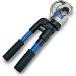 |
| Battery Operated | Cembre B500E | up to 630sqmm LV HV Cable Lugs | 63kN |  |
| Crimp Head + Foot Pump | Cembre ECW-H3D + PO7000 | up to 630sqmm LV HV Cable Lugs | 230kN | 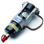 |
Crimping Cables – 6 Steps
Failure to observe these precautions can result in a compression connector, cable lug, cable joint or termination that fails in service.
- Choose a manufacturer providing crimp tooling, die set and crimp lugs matched to work together to give assured crimping performance. Avoid “cross-crimping” where a “dolly mixture” approach to the choice of lugs, tools and dies introduces a cocktail of often incompatible different manufacturers into the crimping process. Achieve a systemised approach i.e. crimp lugs + crimp tools + crimp dies = 1 brand.
- Each crimp lug should be marked with a reference on the barrel or palm – this shows that the cable lug selected is the correct size and type for the conductor. Refer to the die selector to select correct Cembre dies.
- Prepare the conductor by stripping the insulation back. The strip length should be equal to that of the cable lug barrel. Take care to avoid damaging the conductor strands – exposed cable strands should be cleaned to remove any remaining insulation from the LV MV HV cables.
- Fully insert the conductor into the barrel of the cable lug – check the cable conductor is fully inserted using the inspection hole provided.
- Using the manufacturers instructions, crimp the cable lug – paying careful attention to the positioning of the crimp die on the barrel of the lug. If multiple compressions are required pay attention to the sequence in which they are made.
- Use the following 6 points to check the completed crimp:
- Marking on the cable lug shows it is correct for the conductor type and size.
- The marking on the cable lug shows the correct crimping die set was used.
- No insulation is trapped in the cable lug barrel.
- Excess grease is removed from insulation and cable lug.
- If an inspection hole is provided, the conductor has been fully inserted.
- It is not over-compressed or under-compressed. Both of these can have a detrimental effect on the performance of the joint.Incorrect compression can cause excessive flash or burrs. If in any doubt, samples should be produced for test purposes.

In addition to the requirements of BS7609, Cembre advises the following when crimping cables – it is important that the crimped cable installation is not compromised by a poor choice of copper tube lug, or by the use of a ‘mismatched’ crimping system:
- Cembre supports the Approved Cables Initiative (ACI) Code of Practice to ensure that the conductor used is both third-party approved and appropriately marked.
- The cable lug should have an equal current carrying capacity to that of the conductor. Copper tube lugs designed and manufactured by Cembre achieve maximum electrical conductivity with minimum resistance by the use of high purity, electrolytic copper having a cross sectional area equivalent to that of the conductor.
- Beware cable lugs are manufactured from thin wall copper tube as they have the potential to cause elevated temperatures when the conductor is carrying high levels of current.
- Recommended procedures for conductor preparation and crimping Cembre copper tube lugs, including number, position and sequence where multiple compressions are required.
- Cembre copper tube lugs are also fully annealed after pressing to alleviate residual stresses within the palm area and ensure optimum mechanical and electrical performance at the connection interface.
- Ensure Cembre crimp tooling is certified as calibrated regularly and serviced correctly and all equipment, particularly die sets, is inspected for damage or wear and maintained in good condition.

Cembre Crimp Lug Correct Installation
Cable Crimping
Some best practise requirements:
- Approved cable conductor correctly prepared
- Conductor strip length = cable lug barrel length
- Manufacturer and size shown on crimp lug
- Cable lug and conductor have equal copper content
- Crimp tool optimises performance of dies
- Crimp dies matched to tool, lug type and size
- Correct number, position and quality of crimps
- Cable lug marked to check correct dies used
Choosing the correct Cembre die set:
- ALWAYS refer to the Cembre die selection chart. A die selection guide booklet is also included with every new Cembre crimp tool, whether hydraulic crimping tools or battery crimping tools.
The number and sequences of compressions per cable lug:
- The number and sequence of compressions shown in the die selection guides are specifically determined for Cembre lugs from the lug type and design, the force applied by Cembre crimp tooling and the bite width of the matched die set.
- ALWAYS apply the correct number of compressions as per the die selection guide in order to assure the performance of the joint after cable crimping.
- Apply each compression in the correct sequence to avoid distorting the cable lug.
Which Cable lug & die combination to use when crimping extra flexible conductors?
- Cembre copper tube lugs for extra flexible conductors 35sqmm to 185sqmm have the same cross sectional area of copper as standard Cembre A-M lugs for LV applications, but with a slightly wider inner diameter to more easily accommodate the fine strands.
- Above 185sqmm it may not be possible to use the correct size standard lug with an extra flexible conductor. For example, say a 240sqmm lug does not fit on a 240sqmm extra flexible conductor, it is acceptable and common practice to use the next larger size of lug, here 300sqmm.
- The lug MUST however be crimped with the die set appropriate to its size, 300sqmm, since using a 240sqmm die set will distort the cable lug and be detrimental to performance.
Which Cable lug & die combination to use when crimping compacted conductors?
- For low voltage applications use Cembre A-M Copper tube lugs. Matched crimp tooling and hexagonal die sets MUST be used.
- Always apply the rule that the cross sectional area of the lug should at least equal that of the conductor so, when using compacted conductor it is essential that the correct size lug be used, even if the fit appears ‘loose’ prior to crimping.
- The apparent ‘loose’ fit is due to the air between conductor strands having been ‘compacted out’ during manufacture, causing a slight reduction in the diameter of the conductor. The resulting gap between conductor and cable lug barrel wall is fully taken up during the crimping process.
- Do not be tempted to move down a lug size to obtain a tighter fit, as there will then be insufficient copper in the shoulder or palm of the cable lug. As an example, for 185sqmm compacted conductor use A37 lug, ME37-C die set and appropriate Cembre crimping tool.

Cembre
T&D are Main UK Stockists for the Cembre range of compression connectors (cable crimp lugs and splices) for all low and high voltage crimping applications of power, control and instrumentation cables with either copper or aluminium conductors.
Cembre copper, aluminium and bimetallic cable lugs and splices are designed for high voltage cable crimping applications including 3.3kV, 6.6kV, 11kV and up to 33kV. Cembre 2A HV cable lugs and splices are made from high purity copper, annealed and tin plated with extended barrels for reliable high voltage electrical connections.
Cembre electrical connectors are the market leading crimping system for reliability, consistency and peace of mind performance – specify Cembre to crimp, splice and terminate your vital high voltage electrical circuits.
A Quality Comparison – Cembre v Unbranded Cable Lugs
Both of the below copper cable lugs in picture 1 are specified by their respective manufacturers to crimp and terminate 400sqmm stranded copper cables – pictured right is the Cembre cable lug, note the CE Marking. CE marked cable lugs guarantee product compliance with EU safety, health and environmental requirements. Clearly the Cembre lug has increased barrel length and a thicker cable lug wall for an advanced standard of electrical connection with excellent conductivity due to high copper content – the thinner wall cable lug pictured alongside which is a imported and unbranded product is lighter weight and dimensionally smaller than Cembre brand lugs.
When terminating either armoured, unarmoured or braided cable types we recommend only to use branded type cable terminations such as Prysmian cable glands.
Quality – Cembre crimp lugs and splices are manufactured from electrolytic copper tube – the copper tube dimensions are designed to obtain the most efficient conductivity and mechanical strength to resist vibration and pull out. This includes electrical connectors for LV 600/1000V and MV HV cables operating at 11kV/33kV.
Strength – Cembre cable lugs are annealed to guarantee optimum ductility which is an absolute necessity for crimp connectors which must withstand the severe deformation arising when compressed by hydraulic crimp tools. In electrical installations subject to vibration, crimp terminals must perform a reliable connection – annealing avoids cracking or breaks between the cable lug palm and barrel. This applies especially to Marine & Shipboard cables in offshore installations subject to high levels of movement and mechanical stress.
Reliability – Cembre cable lugs feature an extended barrel design facilitating full insertion of the the copper conductor into the crimp lug – the cable lug barrel length has been designed to allow easy and accurate positioning of the dies during the crimping operation.
Note the distinctive quality differentials between the Cembre brand transformer lugs and unknown, unbranded type.

1. Cable Lugs – Low Voltage Single Hole 400sqmm.

2. Transformer Cable Lugs – Cembre Brand

3. Transformer Cable Lugs – Unbranded
Further Reading
- Crimping Aluminium Cables Using Cembre RHU131-C Presshead
- Selecting & Positioning Dies In Cembre ECW-H3D Presshead Tool
- Replacing Cembre Cable Cutting Tool Blades – Model TC055
- Ensuring Optimum Performance Of Cembre Crimping Tool – Model HT131-C
- Cembre B1350-CE v. B135-C Crimping Tools Performance Comparison

Thorne & Derrick – Stickists & Suppliers of MV HV Joints, Terminations & Connectors
Thorne & Derrick
T&D are Specialist Distributors of an extensive range of LV, MV & HV Jointing, Earthing, Substation & Electrical Eqpt – this includes 11kV/33kV/66kV cable joints, terminations and connectors for both UK DNO, private network applications and international cable specification and standards.
Contact our UK Power Team for competitive quotations, fast delivery from stock and technical support or training on all LV-HV products.
Key Product Categories: Duct Seals | Cable Cleats | Cable Glands | Electrical Safety | Arc Flash Protection | Cable Jointing Tools | Cable Pulling | Earthing | Feeder Pillars | Cable Joints LV | Joints & Terminations MV HV
Medium & High Voltage Power Cable Systems – Diagnostic Services
July 6th, 2018
Visit IMCORP, The Cable Experts | Medium & High Voltage Power Cable Systems
-
uploaded by Chris Dodds - Thorne & Derrick Sales & Marketing Manager
IMCORP is the technology leader in Medium & High Voltage Power Cable Systems life cycle condition assessment and performance – IMCORP have been helping their clients achieve maximum cable reliability for more than 20 years and have assessed over 130,000 5kV to 500kV cable systems spanning in excess of 160 million feet.
IMCORP Precision ReliabilityTM approach integrates asset condition intelligence into optimized work management processes to maximize cable system reliability at the lowest possible life cycle cost.
Thorne & Derrick have curated this Twitter Moment to recognise the Global Cable Expert status of IMCORP – we are both honoured and humbled to be able to share our expertise and networks effectively to communicate our message to the broadest audience achievable.
Click the Tweet links for deeper reading.
Top 10 Tweets
- Misplaced Stress Relief Exposing Semicon Screen Cutback On Cold Shrink Terminations
- Identifying Substandard Performance Of Premolded Dead Front MV Tee-Connectors
- Power System – Feeder Cable Joint Failures Leads To Jointing Instruction Improvement
- Identifying Workmanship Installation & Cable Joint Issues At A Solar Site
- Failing Cable Joints Caused By Poor MV HV Cable Preparation Of Semicon Screen
- How Do HV Cables Fail – 10 Defects Causing High Voltage Power Cable Outages
- Failing Cable Joints – Partial Discharge (PD), High Voltage Stress & Cable Joints
- Improper Stress Control Installation On Medium & High Voltage Power Cables & Systems
- Power Cable Damage From Backfill – Medium Voltage Cable Case Study
- Medium Voltage Cable Termination Suffers Partial Discharge (PD) – Cause & Remedy
MV HV Power Cable System Reliability Solutions by IMCORP
💡 Read our Guest Blog with IMCORP ➡
The Semicon Screen – A Most Critical Point In Any MV Joint, Termination Or Connector

Thorne & Derrick
T&D are Specialist Distributors to UK Distribution Network Operators (DNO’s), NERS Registered Service Providers, ICP’s and HV Jointing Contractors of an extensive range of LV, MV & HV Jointing, Earthing, Substation & Electrical Eqpt – this includes 11kV/33kV/66kV cable joints, terminations and connectors for both DNO and private network applications.
Contact our UK Power Team for competitive quotations, fast delivery from stock and technical support or training on all LV-HV products.
All international sales enquiries can be serviced and supplied by our Export Power Team.
Key Product Categories: Duct Seals | Cable Cleats | Cable Glands | Electrical Safety | Arc Flash Protection | Cable Jointing Tools | Cable Pulling | Earthing | Feeder Pillars | Cable Joints LV | Joints & Terminations MV HV

132kV Link Boxes & Bonding Leads For High Voltage HV Cable Systems
June 20th, 2018
Link Boxes For High Voltage Cable Systems | HV EHV 132kV | Transmission & Distribution
-
uploaded by Chris Dodds - Thorne & Derrick Sales & Marketing Manager
HV Link Boxes & Bonding Leads
What Are Link Boxes?
Link boxes are installed on medium/high voltage power systems in conjunction with MV HV Cable Joints & Terminations incorporating a sheath break to prevent sheath circulating currents and limit induced voltage in the cable screen using bonded systems up to 132kV.
Underground cable bonding systems utilising 132kV XLPE insulated HV power cables are designed to provide cable sheath bonding to eliminate or reduce the circulating sheath currents and limit standing induced cable sheath voltages for safety reasons.
In an internal fault condition or short circuit of the high voltage power system the electricity current flows directly and safely to earth via the link box.
High voltage link boxes manufactured from corrosion resistant stainless steel (AISI 304L) are installed in association with cable joints to provide bonding of the HV cable circuit and at both circuit ends of the cable connected to the cable terminations – this product range complements our line of 132kV surge arresters with UK DNO and National Grid Approval.
Thorne & Derrick are Approved Suppliers for EMELEC, who offer an extensive range of electrical MV HV Link Boxes, expertly designed for bonding/grounding connections, made through removable links. We can provide excellent customer support, product selection and competitive prices with next-day delivery from extensive stocks of electrical Link Boxes.

Link Box Types
The standard ranges of single or 3 phase high voltage link boxes:
- Wall / Gantry / Structure Type IP66 – 3 Phase & Single Phase, Single Bonding Link Box (Cable Termination & Joint Location)
- Partial Discharge (PD) Type IP68 – 3 Phase Cross Bonding Link Box With SVL (Cable Joint Location)
- Pedestal Type IP66 – 3 Phase Earthing or Cross Bonding Link Box With SVL (Cable Termination & Joint Location)
- Underground Type IP68 – 3 Phase Cross Bonding & Single Bonding Link Box With SVL (Cable Termination & Joint Location)
- Underground Wall Type IP68 – 3 Phase & Single Phase Earthing Link Box With SVL (Cable Termination Location)
The link box is installed with cable joints and terminations to provide shield break accessibility for HV test purposes and to limit voltage build-up on the cable sheath – overvoltages on the sheath can be caused by fault currents, switching operations and lightning effects.

Multiple configurations are available – call to discuss your link box requirements up to 132kV
132kV
Single Phase & Three Phase Earthing Link Boxes
Thorne & Derrick can supply a complete range of 132kV Link Boxes in accordance with the Energy Networks Association (ENA) Engineering Recommendation C55/4 – ENA is responsible for maintaining the industry developed and published Technical Specifications (TS), Engineering Recommendations (ER) and Engineering Technical Reports (ETR).
ENA is the voice of the networks, representing the ‘wires and pipes’ transmission and distribution network operators for gas and electricity in the UK and Ireland.
The range of single phase and 3 phase High Voltage Link Boxes manufactured by EMELEC are ingress protected to IP66 or IP68 and suitable for indoor/outdoor wall mounting or underground direct burial – the internal connections/links are easily accessed and removed permitting disconnection of the individual sheaths for cable sheath fault testing.
Sheath testing is mandatory to ensure cable sheath integrity has not been compromised by cracks, cuts or snags during the cable pulling and laying installation.
A full set of Type Tests have been completed by the IPH Laboratory in Berlin including:
- Internal Power Arc 40kA/0.1 second
- Short Circuit 50kA/1.0 second
- Lightning Impulse 40(60)kVp
- DC Withstand 25kV/5 minute
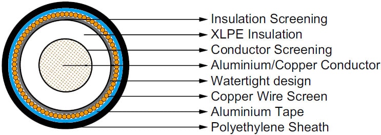
Typical 132kV Cable Construction – IEC 60840
Link Box Routine Testing
All high voltage link boxes are factory tested before shipment to customer – applied tests include visual and dimensional inspection followed by electrical tests such as AC/DC Withstand Test, Insulation Resistance Measurement Test and Contact Resistance Measurement Test.
Link boxes are available with screen bonding options including:
- Cross Bonding With SVL (Sheath Voltage Limiters)
- Direct Earthing Without SVL
- Earthing With SVL
- Single Point Bonding With SVL
Surge Arresters & Sheath Voltage Limiters
Thorne & Derrick can also supply Sheath Voltage Limiters to suit the HV cable system bonding arrangement as well as Normal Bonding Leads, Concentric Bonding Leads and High Voltage Earthing Kits for connection between the link box and the cable accessory.
SVL’s are protective devices to limit induced voltages on the bonded cable system installation due to short circuits – SVL’s are installed between the metallic screen and ground inside the link box.
The screen separation of the power cable joints would be protected against potential damage inflicted by short circuit/break down. SVL rated voltages can be produced in accordance with client specification and the bonding system design requirements.

Bonding Cable Leads – Single v Concentric Leads
Bonding Leads
Single Core Bonding Leads | Concentric Bonding Leads
An integral component of a Specially Bonded System is the use of bonding leads with the correct physical and electrical properties for high voltage power cable system earthing – 120sqmm, 240sqmm, 300sqmm and 500sqmm single core and concentric type leads are available for use with 132kV link box installations in buried or gantry mounted applications.
The bonding system is critical for improving and stabilising current carrying capacity of the power system – Engineering Recommendation C55/4 describes in detail the cable specification, system design and installation for HV bonding leads.
Thorne & Derrick supply both normal and concentric bonding leads with conductor sizes from 120sqmm-500sqmm compliant with the physical and electrical specification established in Engineering Recommendation C55/4.
Fire retardant sheaths can be manufactured for tunnel or substation basement applications.
Common size bonding leads are generally available from stock.
Single Bonding of High Voltage Cables – the simplest form of special earth bonding consists in arranging for the cable sheaths of the three HV cables to be connected and bonded at one single point along the circuit length without cable joints and typically comprising shorter cable circuits. At all other points, a voltage will appear from sheath to ground that will be a maximum at the most distant point from earth bond. The high voltage cable sheaths must be adequately insulated from the ground – since there is opened sheath circuit (except through the SVL) current does not normally flow longitudinally along the cable sheaths and no sheath circulating current loss in incurred.

Single Bonding – Bonding Leads
Cross Bonding of High Voltage Cables – consists essentially in sectionalising the cable sheaths into minor sections and cross connecting them so as to approximately neutralise the total induced voltage in 3 consecutive sections as show below. Typically, the HV cables are sectionalised into 3 equal length sections and cross bonding is achieved within the link box.
Pictured: Typical layout of 132kV Joint Day design with location of link box pit and bonding cables positioned.


Cross Bonding – Bonding Leads


National Grid Type Registration
The full range of EMELEC Link Boxes have completed the National Grid Type Registration process. The Registration covers wall-mounted and buried link box types, across the voltage range 132kV – 400kV and is supported by authoritative test data from the IPH GmbH high voltage laboratories.
Globally, cable manufacturers and utilities specify and install EMELEC link boxes – recognising the proven consistent quality, durability and suitability of the HV EHV link boxes.
Link boxes are a critical component in any high voltage underground cable system, either for direct earthing or through Sheath Voltage Limiters and their reliability is essential for fully efficient operation including human safety. In the event of a system fault the short circuit current goes directly to earth through the link box in a controlled manner.
Contact Thorne & Derrick with link box and bonding lead sales enquiries for National Grid, UK DNO and IDNO project requirements.

Cable Joints, Terminations & Connections | 3M | Pfisterer | Nexans Euromold
Care & Maintenance Of Separable Cable Connectors For High Voltage Power Systems
June 7th, 2018
-
Uploaded by Chris Dodds - Thorne & Derrick Sales & Marketing Manager
Thorne & Derrick International, were recently asked by an installer of MV HV Power Cables & Systems to comment on the condition and service performance of some screened separable connectors into medium/high voltage switchgear. The contractor had suffered a succession of switchgear cable termination failures and there was uncertainty about trouble-shooting the root cause – whether poor workmanship from the cable jointers or improper routine maintenance were the main cause. The contractor understood that the MV-HV terminal of the separable connector, pictured below Interface C bushing, should be treated once or maximum twice a year with silicone grease.
As Main Stockists & Distributors for the Nexans Euromold range of cable joints, terminations and connectors for high voltage power systems we decided to ask their Technical Manager for a response.

Reply from Mick Dawn – Nexans Technical Manager (Nexans Power Accessories NPA)
These are not Nexans connectors, they are Tyco separable connectors. However, I will comment on the silicone grease suggestion as it would also be relevant to Nexans and other manufacturers of MV HV screened separable connectors. There is no reason to “treat” the contact within the separable connector with grease. In fact, Nexans expressly state in our installation instructions that lubricant is not present on threaded parts as this may interfere with achieving the correct torque. The purpose of the contact is the safe transfer of electrical power between the MV-HV cable and the electrical equipment and applying grease will not facilitate any improvement in that operation and may well contribute to failure as grease between current carrying components may well lead to a high resistance contact and considerable heat generation. If the separable connector has failed then this could be down to any number of factors and if necessary a fault investigation can be carried out and generally a rational explanation can be deduced as most of the connector will still be available for examination. Even if there has been significant heat damage due to poor connection then it is usually still possible to determine a cause of failure.
➡ The following image taken from Nexans Connectors – Installation Instruction Separable Tee Connectors (Type C Interface) Document
The image shows the insertion of the clamping screw into the threaded hole of the bushing. A torque wrench is used by the jointer with a socket wrench 22 and tighten exerting 50 Nm (5 kgm or 36,9 foot-pounds) of torque. In order to achieve the correct applied torque ensure that there is no lubricant on the threaded parts.
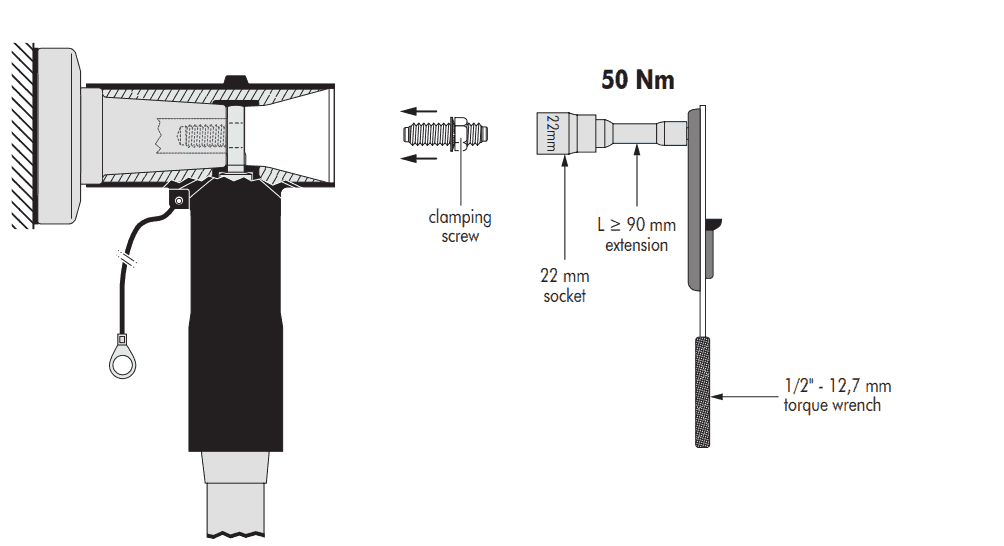
Nexans Connectors – Type C Bushings

Thorne & Derrick MV HV Joints | Terminations | Connectors
Thorne & Derrick
Key Product Categories: Duct Seals | Cable Cleats | Cable Glands | Electrical Safety | Arc Flash Protection | Cable Jointing Tools | Cable Pulling | Earthing | Feeder Pillars | Cable Joints LV | Joints & Terminations MV HV
Some Thoughts On MV HV Heat Shrink Cable Joints & Cable Terminations
May 30th, 2018
Heat Shrink Cable Joints & Cable Terminations | Manufacturers & Assemblers
uploaded by Chris Dodds - Thorne & Derrick Sales & Marketing Manager
Although modern cable manufacturing technologies evolve and develop the essential factors to consider when installing heat shrink type joints or terminations on medium/high voltage power cable systems remain essentially unchanged. Materials quality allied with installation by competent trained Jointers is the fundamental basis to ensure reliability, safety and operational service of MV HV cables, joints and terminations.
Here, from the archive we reproduce an important Technical Article by Norman Poulter – Norman was the Managing Director of Shrink Polymer Systems, the UK’s leading specialist manufacturer and assembler of MV HV cable joints and terminations for standard and non-standard cable applications up to 33kV.
Today, SPS’s Managing Director Richard Poulter continues to support the UK and overseas market with the competitive supply of MV HV heat shrink cable accessories for all cable voltages including 11kV/33kV and types such as XLPE, EPR, PILC and Triplex cables.
Medium & High Voltage Cable Accessories
author Norman Poulter
Power cable installation throughout Europe and the UK until the early 1960s exclusively used impregnated paper for the primary insulation of the conductors for both single- and three-core MV-HV cables.
The UK adopted both aluminium and lead-sheathed cables with and without steel wire armouring (SWA); these are still in use today. In the very early days of paper-insulated cable terminations, dry-type systems were employed along with compound-filled end box designs and cast-iron boxes with hot pour bitumen for cable joints.
PILC SWA Paper-insulated Lead Covered & Steel Wire Armoured Cable
- Circular stranded copper phase conductors
- Conductive paper screen
- MIND paper insulation
- Metallised paper insulation screen
- Circularising fillers
- Lead sheath
- Bitumenised hessian bedding
- Galvanised steel wire armour
- Bitumenised hessian serving with whitewash coating
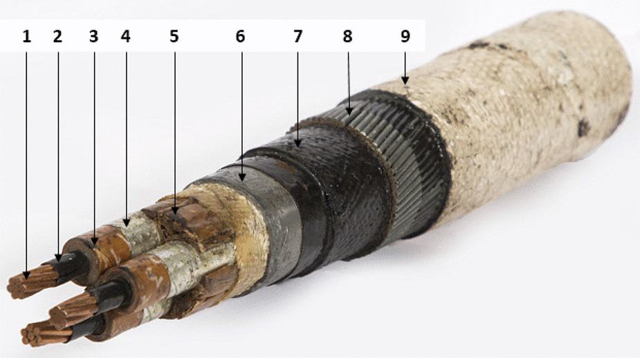
11kV PILC Cable
Cold shrink products such as push-on, pre-stretched tube and grease applied slip-on types also became popular in the 1960s and are still specified by specific electric authorities and utilities for terminating and jointing MV-HV cables.
In the early 1970s polymeric (XLPE) cable types began to emerge in Europe and the UK, mainly on three-core cables, while the USA employed the single-core cable concept at 10kV, 20kV and 35kV medium voltages.
The heat shrink concept began to be employed at this period by the utility companies and has now spread internationally as the preferred method of cable terminating and jointing.
There are many advantages of using heat shrink cable accessories and techniques, such as:
- Wide shrink ratio – one joint/termination kit assembly to cover numerous cable ranges
- Heat concept dries out moisture from the MV HV cables
- Mastic seals are activated by heat so sealants are usually visible at sleeve ends
- They are not size sensitive and can be used on sector-shaped conductors
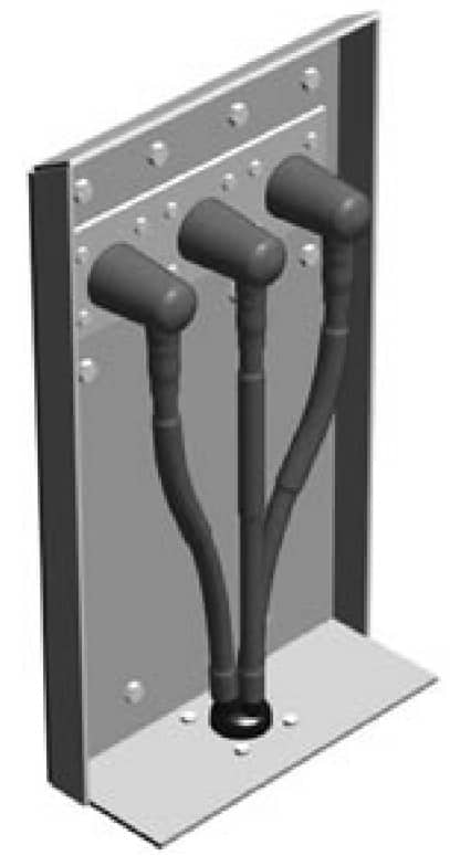
Figure 1 – Cable Box Air Insulated Termination
Cable Joint & Termination Kit Instructions
Shrink Polymer Systems also realised the importance of good cable jointing and terminating instructions. By using pictorial drawings with a minimum of text, non-English speaking countries can identify the important highlighted areas in an easily identified format.

Cable Terminations 11kV 33kV – Instruction Excerpt
Failures are nearly always attributed to poor cable preparation by the jointer and failure to observe the correct jointing procedures in the areas where the electric cable stresses are prudent, such as the semicon screen cut back.
Although the USA shares a language with the UK, there are many differences in the selection of words to describe various things. Below is a list of some UK terminology and the common equivalent used in the United States.
- Core – Conductor
- Screen – Shield
- Joints Jointing – Splice Splicing
- Cable Jointers – Cable Splicers
- Earth Earthing – Ground Grounding
- Armour Support – Reinforcing
- Metal Sheaths – Armour
- Self-Amalgamating – Self-Fusing
Heat Shrink Cable Joints
& Cable Terminations
Terminations
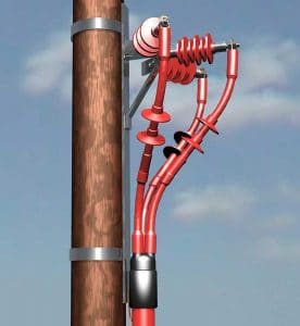
Terminations | Indoor or Outdoor
The major MV HV switchgear and transformer manufacturers have, for many years, designed dry-air filled cable boxes, resulting in a much greater demand for heat shrink-on terminations.
All heat shrink cable terminations and joints have to be tested to various international standards, and while cables prepared by experts in perfect laboratory conditions will undoubtedly meet these requirements under test, field experience shows that failures still occur at working voltage due to a variety of reasons.
Typical List Of Weakness Resulting In Failures
Of Heat Shrink Terminations
- Compression lugs, or crimp lugs, fitted to outdoor terminations of the compression tube type with inspection holes allowing moisture to penetrate the conductor cores.
- Failure to eliminate air pockets on paper-insulated, lead covered (PILC) three-core “belted” cables in the crotch area.
- Core crossing resulting in discharge if cores are too close to each other in an unscreened area at the core cross point. This results in the air “breaking down” electrically at approximately 4kV on an 11kV cable, 6kV on a 24kV cable and 9kV on 36kV cable. The anti-track heat shrink material then begins to erode due to the ionisation of the air, which over time will inevitably cause failure of the cable termination.
- Poor cable preparation, in particular on extruded dielectric types where insufficient care is taken on semiconductive screen removal at the crucial area of the screen cut-off. Cable jointers are generally reluctant to purchase engineered screen removal tools and rely on knives, blades and homemade tools for removal. This can result in cutting through the screen and into the primary insulation, leaving voids which result in the discharge phenomena described in the third item above. Even well-prepared screen removal at the cut-off point can result in a possible void, as the stress control tube may not follow the semi-conductive edge profile. (See figure 2.)
- Moisture penetration due to poor heat shrink and mastic sealing techniques.
- Inadequate phase-to-phase and phase-to-earth clearance.
- Tracking.
- Poor cable jointing instructions.
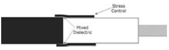
Figure 2
There are solutions and remedies to these weaknesses relating to MV HV cable accessories which will be described later in the article.
Joints
Many of the points discussed regarding cable terminations are also relevant to joints.
The object of the cable jointing exercise is to replace all the materials that were removed to joint the conductors and replace them in such a way as to replicate the cable as closely as possible to its original state.
There are many techniques used in conductor jointing from “sweating” the weak-back ferrule (normally associated with the original cast iron paper joints) to compression and the present popular “shear bolt” designs.
Connector jointing is a complex subject due to the variety of designs for copper and aluminium conductors in circular-solid, circular-stranded, and sector-shaped styles.
There is also the consideration of copper being jointed to aluminium, cables of unequal cross sectional area being jointed to themselves, and transition jointing where paper is being jointed to polymeric at medium or high voltages.

Figure 3 An 11kV 3 Core Heat Shrink Cable Joint
Let’s look at some of these designs.
Compression Connections – Crimps
There are a substantial number of manufacturers, such as Cembre, who specify suitability of their electrical connector design for voltages up to 33kV/36kV. Caution is needed if the body of the barrel is not smooth and does not have tapered ends.
Also, responsible MV HV connector manufacturers will be able to manufacture appropriate crimping tooling for their designs or confirm the compatibility of other cable tooling and die combination for their connectors. There are three types of crimping configurations currently in use: hexagonal, oval, and indent.
For instance, the Cembre HT131-C is the industry standard hydraulic crimping tool used by LV HV cable jointers to install copper type lugs and splices onto stranded cable conductors.
Oval and hexagonal crimping can leave sharp “ears” if incompatible tooling is used.
These “ears” must be filed smooth to avoid a highly stressed area which will be subjected to electrical discharge. Indent crimping will leave void holes which must be filled with high permittivity, stress relief tape.
Mechanical Connections – Shearbolts
Mechanical split type connectors are now very popular in the UK, as this design comes in two halves which are easy to apply to three-core cables at 11kV or 33kV where the cable conductors do not have to be bent. The heads shear-off at a given torque; therefore, no compression tooling or die combinations are necessary.
As this connector is “blocked,” it is also suitable for transition cable jointing for paper to plastic to stop the migration of the paper oils. There are several disadvantages of this type of connector, however. The ends of connector are non-tapered, resulting in high “step downs”, and the conductor insertion is non-centralised. (See figure 4.)

Figure 4 Mechanical Shearbolt Connector
These two conditions result in areas of high electrical stresses leading to probable discharge.
Shrink Polymer systems have now standardised on a shearbolt connector design where these critical areas of high stresses are removed by tapering the ends and centralising the conductor. (See figure 5.)
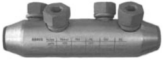
Figure 5 Mechanical Shearbolt Connector (Tapered)
Stress-Relieving Tapes
This type of stress relief tape generally has permittivity values between 7 and 13 (test method IEC 250). (See figure 6.) This does not necessarily mean that a value of 13 will perform better than a value of 7, as void filling characteristics are equally as important.
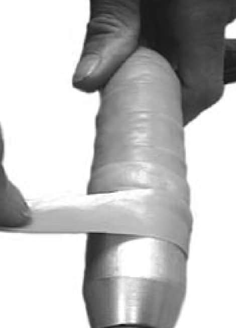
Figure 6 MV HV Connectors & Stree Relief Tape
Shrink Polymer Systems have a yellow stress control tape, reference number TS 31785Y, which possesses high tack, high stretch, and low viscosity void-filling qualities with a permittivity value of minimum 9. Whichever type of cable connector is selected, stress-relieving tape must be used in conjunction with heat shrinkable installations.
This is applied in a half width overlap with stretch by the cable jointer and must also be applied to any indents left by the tooling.
Gaps between end of primary insulation and connector must also be filled in.
Push-on molded components are also widely used, eliminating the need to fill voids and use stress tapes.
They rely on the Faraday Cage principle, in which conductive rubber-ribbed moldings are in contact with the connector. As the potential difference across the air is very low, discharge should not occur. Push- on molded components, joints and terminations have several disadvantages however.
On three-core cables the molded components prove to be very bulky and have no design features to eliminate moisture penetration unless used in conjunction with large diameter shells and resins. On large aluminium conductor sizes the ferrule could possibly be longer than the moulded component. The positioning over the ferrule is critical.
Stress Control Heat Shrink Tubing
Shrink Polymer Systems employ the heat shrinkable, high permittivity, and low resistivity stress control tubing which is shrunk onto the stress relief tape using heat applied by a jointers gas torch previously applied.
This has the effect of achieving a more uniform distribution of the field lines. This heat shrink tube extends over the ferrule or connector and onto the prepared screen cut-off points of the medium/high voltage power cable (See figure 2.)
Insulation Thickness
When designing cable jointing systems, the thickness of the insulation over the bare conductor (i.e. ferrule) should have a safety factor in excess of 15% of the original cable.
Shrink Polymer Systems employ a one-piece, combined dual wall (insulation / semiconductive) heat shrink tube of appropriate diameter to match this insulation at voltages to 11/12kV.
At 17.5kV, 24kV and 36kV additional heat shrink insulation tubes are added to meet these cable specifications.
The cable jointer must remember to shrink this material all around the heat shrink tube to avoid inconsistent wall thicknesses on full recovery.
Typical List of Weaknesses Resulting in Failures
- Incorrect crimping of connector.
- Air trapped in connector (if indent crimps not filled).
- Air trapped between end of insulation and end of connector.
- Discharge at screen ends caused by poor stress taping / cuts to primary insulation.
- Moisture ingress entering cable sheathing through poor sealing.
- Inadequate insulation levels over connector.
- Poor cable termination or cable joint kit instructions.
The solutions and remedies to these weaknesses are described below.
Earthing Cable Terminations
Earthing must be provided to carry any circulating currents to core screens, metal sheaths and armour wires. It must also have the ability to carry fault current. On indoor MV HV cable terminations the use of tin plated copper, solder-blocked braids, metal canisters, armour support, clamps and a complete corrosion protection system should be employed.
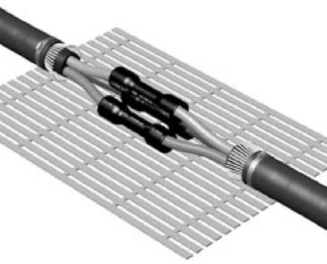
Figure 7 Low Voltage Heat Shrink Cable Joint For Multicore Cables
Earthing Cable Joints
Connecting the earthing components across a heat shrink cable joint requires correctly choosing and fitting the components to take care of both circulating currents and the short circuit requirements.
The outer semiconducting layer of the core/connector insulation should be wrapped in a tin copper mesh bandage and connected to the cable earth at each end.
There are a great many variations and earthing complexities and such a wide variety of cable types to consider.
Once a cable type, size, and voltage are specified it should be left to the manufacturer to supply the correct type of earthing system to meet both the national and local standards.
Remedies & Solutions To Overcome Cable Termination Failures
- Always use one-piece solid lugs for outdoor termination, not squashed tube type.
- Wrap butyl self-amalgamating tape around crotch and under lead cut on three-core belted cables to eliminate air. Check clearance dimensions on three-core cables.
- Care must be taken in semicon screen removal not to nick the primary insulation at the screen cut-off point.
- Ensure all mastic seals are in place on bushing boots, rain sheds and core tubes.
Remedies & Solutions To Overcome Cable Joint Failures
- Ensure cable connector is free from “burrs,” sharp points, not squashed tube type.
- Fill in all gaps with stress tapes before applying stress control tubing.
- Ensure correct application of stress tape at screen cut-off points. (See figure 2.)
- Fit all seals as supplied, in particular at crotch area, under armour beddings and end of connector insulations.
Cable Jointing & Terminating Instructions
It is the responsibility of cable accessory manufacturers to supply easy-to-read, simplified, pictorial jointing instructions and to avoid heavy reading of text manuals.
This point cannot be overstated, as, in the writer’s opinion, far too many jointing instructions are not read or understood, resulting in the installer compromising on the areas of importance previously mentioned. This all too often results in that first failure.
How Can We Help?
Since 1985 Thorne & Derrick have been servicing the UK and Export market with Joints, Terminations & Connectors for LV MV HV cables and power systems – call us to discuss your requirements including specialist LV cable joints for high performance applications including hazardous areas, marine and offshore cables, fire resistance cables and low smoke zero halogen cables.
Thorne & Derrick
Key Product Categories: Duct Seals | Cable Cleats | Cable Glands | Electrical Safety | Arc Flash Protection | Cable Jointing Tools | Cable Pulling | Earthing | Feeder Pillars | Cable Joints LV | Joints & Terminations MV HV

HV Cable Joints & Cable Terminations | Heat Shrink | 6.6kV 11kV 33kV Cables


