uploaded by Chris Dodds - Thorne & Derrick Sales & Marketing Manager
Cable Abandonment Kits
Onshore & Offshore Power Cables
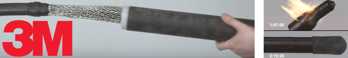
3M Cold Shrink Cable Abandonment Kits are suitable to abandon onshore and offshore polymeric (XLPE and EPR) insulated cables with lead sheath and steel wire armour or wire braid (galvanised steel, phosphur bronze or stainless steel) – this includes both single and multi-core unscreened power cables, 600/1000 volts up to 3.3kV.
Cable abandonment kits are generally employed to abandon cables in the offshore, marine, petrochem, nuclear and power industries on decommissioning projects. Decommissioning projects in the oil and gas sector include a requirement to safely abandon offshore power, control and instrumentation cables – 3M CSCAK kits effectively “ground” the abandoned (redundant) cable circuit thereby avoiding potential electrocution shock to engineers caused by inadvertent future energisation.
3M CSCAK kits are specified for routine offshore cable maintenance and final platform cable decommissioning where topside, subsea and drill site cables must be abandoned.
Between now and the mid-2050s, around 470 platforms, 5,000 wells, 10,000km of pipelines and 40,000 concrete blocks will have to be removed from the North Sea. Source: FT.com.
Using Cable Abandonment Kits
3M Cable Abandonment Kits require no heat source to install – “cold-applied” – and are therefore suitable for use in Zone 1 and Zone 2 hazardous areas with potential explosive atmospheres according to the ATEX Directive. No “hot-working” permits, no naked flames required.
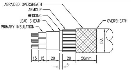
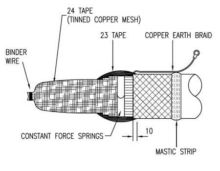
Fig 1 : Prepare the cable as indicated below exposing the primary insulation, lead sheath, bedding, armour and cable oversheath – abraid the cable sheath and clean using suitable cable cleaning wipesfor 50mm.
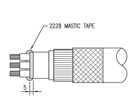
Fig 2 : Apply 3M 2228 Mastic Tape to seal the cable crutch over lead sheath and between the cable cores – 3M 2228 Scotch tape should overlap 5mm on to cable bedding or lead sheath (if applicable).
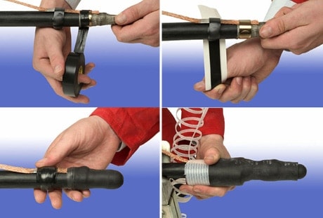
Fig 3: Wrap 2 half lapped layers of 3M Scotch 24 Tape over the cable to be abandoned starting at the conductors up on to the cable armour – use binder wire over the conductors and lead sheath (where applicable) to ensure contact. Fit 3M Constant Force Spring over the Scotch 24 Tape and cable armour – if an earth is required this should be fixed between the Scotch 24 Tape and cable armour. Over tape the 3M Constant Force Spring with 2 layers of highly stretched 3M Scotch 23 Self Amalgamating Tape applied in the same direction as the spring. Continue up over the cable oversheath for 10mm.
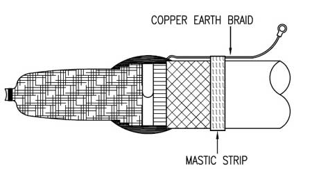
Fig 4 : Where an earth braid is being used apply 1 layer of mastic strip around the cable sheath at given dimension, push braid into mastic and apply a second layer over the braid.
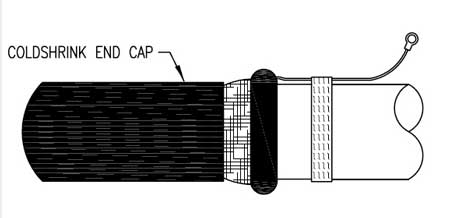
Fig 5: Position the 3M Cold Shrink End Cap over the end of the cable as shown – shrink onto the cable by unwinding the core.
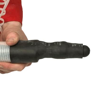
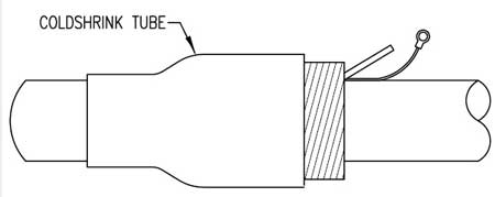
Fig 6 : Position the 3M Cold Shrink PST (Pre-Stretched Tube) over the cable to be abandoned – commencing 15mm on end of end cap shrink down the 3M Cold Shrink PST by unwinding core in an anti-clockwise direction.
Cable Abandonment Kit Selection Table
The following 3M CSCAK selection table is based upon low voltage power cable type according to BS5467 – XLPE insulated cables including aluminium wire armoured (AWA) single core cables and steel wire armoured (SWA) multicore cables, 600/1000 volts.
➡ Offshore Cables. Cable abandonment kits are available to suit halogen free (zero halogen), flame retardant, MUD resistant, heat resistant and fire resistant offshore and ship board power, control, instrumentation and lighting cables – including NEK606 (RFOU BFOU EPR TCWB) and BS6883/BS7917 (UKOOA) Cables.
➡ Watch the Video Demonstrationproduced by 3M Electrical:
LV Cable Joints (Low Voltage Cables)
Thorne & Derrick stock and distribute LV Joints in Cold Shrink, Heat Shrink or Resin Cast technologies – multicore and multi-pair cable joints are available for immediate backfill and energisation of Low Voltage power, control and instrumentation cables 600V/1000V 3.3kV.
Thorne & Derrick invited Giles Davidson (Area Sales Manager at Lucy Zodion Ltd) and Robert Ashworth (Export Sales Manager – Lucy Zodion Ltd) to guide us through the technical and terminological differences between using cut outs and isolators for roadway, tunnel, urban, industrial and street lighting applications.
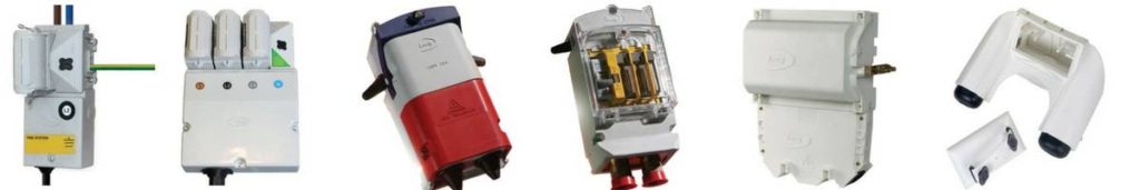
Lucy Zodion is a leader in the design and manufacture of Street Lighting Equipmentin the UK – this includes feeder pillars and appropriately cut outs and isolators for industrial power, street lighting and house service applications.
➡ Let’s let Lucy Zodion educate and inform us on the key differences.
“Confusingly, some people refer to cut outs as isolators and isolators as cut outs, that’s probably not what you want to hear, and to be honest as a manufacturer neither does Lucy Zodion. Although the descriptive terms are loosely treated as interchangeable there are clear distinctions between the two product types.
Let’s get back to basics, in essence both cut outs and isolator products set out to do the same thing, they are both primarily used in the street lighting market.
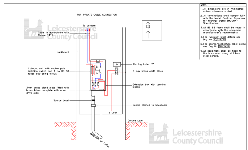
Cut outs and isolators are installed behind the column door at the base of a lamp post (or street lighting column to give it its correct title) – both comprise of an enclosure which is used to terminate a low voltage supply cable (typically with SWA armour and XLPE insulation according to BS5467) and provide electrical protection and a means of isolating the light on the street lighting column.
If it’s the installers choice on what to install, both products would be suitable, however the choice isn’t always down to the installer, so they should consult with their client to see if they have a specification they need to comply with.
So, if both products do the same thing, what is the difference between a cut out and an isolator?
Titans & Trojans…………
Cut Outs
OK, a cut out has its own British Standard – BS7654, there’s a nice easy number to remember!
BS7654 is the specification for single-phase street lighting cut-out assemblies for low voltage public electricity distribution systems.
This BS standard covers all aspects of the cut out from the materials it’s manufactured from to a series of tests relating to temperature, ingress protection, current, mechanical strength; it even states its physical size.
You should ask if the manufacturer has independent certification, good ones will and should be happy to send you a copy without hesitation.
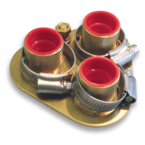
The cut out will come with a set of terminal blocks designed to accept cables up to 25sqmm and will have a suite of accessories that include extension pieces and brass and plastic cable entry plates to suit different types of cable and to make installation and cable glanding as easy as possible.
➡ Pictured Opposite:Brass or insulated gland plates are available in one, two or three entry formats – the cable gland plates are able to receive 20mm, 25mm or 32mm brass tubes for the termination of SWA cables or alternatively grommets and cable glands of the sizes indicated in the Selection charts.
The fuse in the cut out is contained within the cover of the unit, the action of removing this cover disconnects the fuse (so it can be replaced) which also isolates the load from the supply.
Better cut out designs (such as Lucy Zodion of course) have a lever cam action handle on the cover which saves greatly on grazed knuckles or falling backwards into the road when removing the cover.
It’s worth pointing out that although the terminals are isolated removing a lid from a cut-out to change the fuse should only be performed by a qualified electrician.
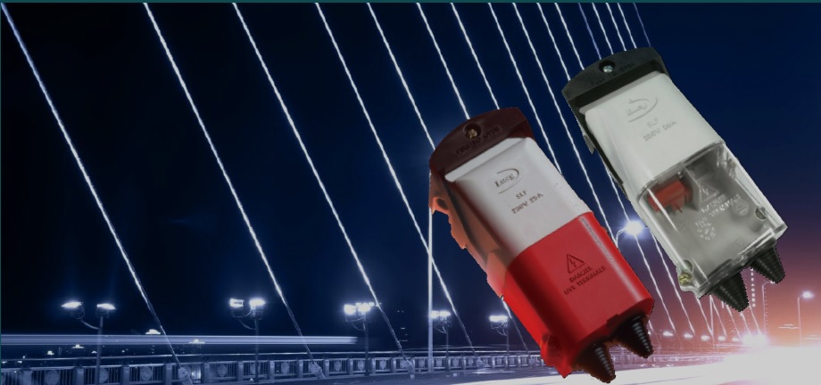
Cut outs only come in either a single or twin fuse version with the option of using digital timers or RCCD’s to control or give additional protection aren’t available – see the reliable and durable MC040SLF single phase cut outfrom the Lucy Zodion range of Titan cut outs available with Type 1 Separate Neutral & Earth ( SNE) and Type 2 Combined Neutral / Earth (CNE) for PME applications, 25A maximum fuse rating.
Cut outs only come in either a single or twin fuse version and it isn’t possible to use digital timers or RCCD’s to control or give additional protection.
♦ BS7654 : This British Standard specification is for single-phase street lighting cut-out assemblies for LV low voltage public electricity distribution systems. 25A rating for highway power supplies and street furniture applications and installations.
Firstly the main body or enclosure of the isolator is not covered by a BS, however reputable manufacturers will still produce the body in the same material as the cut out, and again independent certification should be available.
Factors like a high tracking index and self-extinguishing plastics are vitally important when it comes to safety.
The isolator is in essence an enclosure with a DIN rail that typically can accept products like MCB’s and fuse carriers which are in total no more than four modules in width (a module is a product 17.5mm in width). Think of an isolator as a mini distribution board if you will.
The isolator provides a “switch” which can be operated in order to isolate the load circuit, therefore compared with a cut out changing fuse(s) and isolating the load circuit is relatively simple.
Typically the isolator comes with a 32 amp isolator, hence the name, and a fuse carrier, however as the product has a DIN rail different arrangements and components can be use e.g. digital timers, MCB’s, RCBO’s, RCCB’s, contactors, push buttons etc.
An isolator can form the basis of a unit used for Festive Decorations for example.
One thing that doesn’t come as standard with a street lighting isolator is a set of terminal blocks for the incoming cable (unlike the cut out); so the engineer or installer needs to take this into serious consideration and add in terminal blocks to the final assembly to ensure safe and reliable installation is possible.
The isolator range will also have a suite of accessories that include extension pieces and brass and plastic cable entry plates to suit different types of cable and to make installation as easy as possible for all types of armoured (SWA) and unarmoured cables.
Note that the addition of extension troughs does of course add length to the assembly of the isolator so it is important to ensure that sufficient room is available in the lighting column to accommodate the isolator.
Power Management & Control Equipment For Street Lighting
Summary
So in summary, the cut out is a great work horse providing a method of terminating cables in straightforward situations where no more than two load circuits are needing protection.
The isolator can offer greater flexibility of protection and control but can be more complex in some scenarios.
Unless there is a local authority specification or similar, in most cases the choice of cut-out or isolator will be determined by the type of installation and the functions required.
If you know the size and type of incoming cable, whether it is looping in and out or not, if it is single or three-phase, plus the number of outgoing circuits required (often the number of lights on the column), then this is 95% of the information needed to work out what is needed. Beyond this the checks are mostly physical size etc.
The cable termination specification and engineering standards vary according to the street lighting engineer and the local authority system requirements – a comprehensive range of standard and customised cut outs and isolators are available from stock with short delivery lead times. Our design and build service enables the configuration of isolators with various DIN rail mounting modules.
The Lucy Zodion Range
Lucy Zodion and T&D are pleased to offer advice and assistance – Lucy Zodion fused Titan and Trojan cutouts and isolators provide DNO primary and secondary isolation with extension boxes suitable for SWA armoured cable tails and concentric cables.
uploaded by Chris Dodds - Thorne & Derrick Sales & Marketing Manager
Electrical Submersible Pump (ESP)
Cable Repairs
Electrical Submersible Pumps (ESP) are used to lift oil from a production well, so it is important that the supply cables are reliable and operate safely for an extended service life in the harshest offshore downhole environments.
The ESP cable used to transmit power and sensor outputs to and from the surface is a key component in an ESP installation. The cable must withstand mechanical abrasion, corrosion, high temperature and pressure and should be available in a variety of cross-sections and configurations so the space the cable takes in the well bore is optimized and it can be installed or retrieved easily.
Schlumberger RedaMAX 400 is a 5kV-8kV high voltage cable designed specifically for use with electrical submersible pumps, however the cable can also be used within onshore and offshore gassy wells and other high temperature applications in the oil and gas industry with ESP systems installed.
The benefits associated with the RedaMAX 400 ESP submersible pump cable include lower life cycle cost, long insulation life and longer ESP system life – with EPDM insulation-jacket compounds, galvanised steel armor and lead barrier the power cables temperature rating up to 232°C provides consistent delivery of electrical power to downhole equipment.
The ESP cable is available in three options including the common round profile option but also a flat cable version – in this post we provide information about cold shrink tubes for use with ESP cable repair applications.
RedaMAX 400 ESP Cable Specifications
The 3 versions of the Schlumberger RedaMAX 400 cables are available in different voltages :
Deep water, subsea, high temperature, high horsepower
ELBE, ELB, EHLTB, SESLTBE
3M EPDM Rubber Cold Shrink Tubes
When repairing Schlumberger RedaMAX ESP Power Cables it is advisable to use the 3M EPDM Connector Insulators 8420 Series Cold Shrink Tubes.
This insulating tube forms part of the wider range of cold shrink tubesavailable from 3M Electrical and distributed by Thorne & Derrick.
There are many benefits of using cold shrink technology :
Simple installation, requiring no tools or heat shrink torches – ideal for “explosive atmospheres” and hazardous area locations
Can accommodate a wide range of LV HV cables – Cold Shrink is a versatile cable repair solution
Good thermal stability and tight seal around the cable sheath jacket profile
Fungus, acid and alkali resistant for onshore and offshore aggressive applications
Excellent wet electrical properties for offshore installations
3M EPDM cold shrink tube forms a cable sheath repair when it is applied around the electrical connector and the cable itself.
3M Connector Insulators 8420 Series Cold Shrink Application
Insulation of inline conductor transition connectors
The insulating cold shrink tube is made from EDPM rubber containing no chlorides and six diameter sizes will cover a full range of 1000 volt cables.
In addition to ESP cables, the 3M 8420 Series EPDM tubes can be used in other applications including dig-in and cable sheath repairs, insulation of secondary cable splices and primary electrical insulation for all solid dielectric (rubber and plastic) insulated wire and cable splices rated to 1000 volts.
3M Cold Shrink EPDM Tubes
Connector Insulator 8420 Series
Selection Table
3M Cold Shrink Tubes Part No
Suit Conductor Sizes AWG & Kcmil
Min Diameter (mm)
Max Diameter (mm)
Length (mm)
8423-6
6 – 4
7.8
14.3
152
8425-7
2 – 1/0
9.9
17.8
178
8425-8
2 – 1/0
10.2
20.8
203
8426-11
2/0 – 250
13.0
25.4
279
8426-9
2/0 – 250
13.0
25.4
229
8427-12
250 – 400
17.5
33.0
305
8427-16
250 – 400
17.5
33.0
406
8427-6
+++
17.5
33.0
152
8428-12
450 – 800
24.0
49.3
305
8428-18
450 – 800
24.0
49.3
457
8428-24
450 – 800
24.0
49.3
609
8428-6
+++
24.0
49.3
152
8429-12
900 -1000
32.2
67.8
305
8429-18
900 – 1000
32.2
67.8
457
8429-6
+++
32.2
67.8
229
8429-9
+++
32.2
67.8
152
8430-18
1250-2000
42.6
93.7
457
8430-9
+++
42.6
93.7
229
8430-18
1250-2000
42.6
93.7
457
8430-24
1250-2000
42.6
93.7
610
+++ Primary Cold Shrink Use: Sealing cable lugs and terminal barrels, conduit couplings and conduit-to cable breakouts
LV Cable Joints (Low Voltage Cables)
Thorne & Derrick stock and distribute LV Joints in Cold Shrink, Heat Shrink or Resin Cast technologies – multicore and multi-pair cable joints are available for immediate backfill and energisation of Low Voltage power, control and instrumentation cables 600V/1000V 3.3kV.
Manufactured & Designed In UK | Short Lead Time | Transformers LV 11kV
♦ Guest Post from Richard Kerr & Lindsay Brownless from Powerstar
11kV Transformers
The Next Generation Of Distribution Transformers (LV HV Up To 11kV)
Powerstar SO-LO range of super low loss transformers are the only amorphous core transformers designed and manufactured in the UK and provide a cost-effective way of reducing energy consumption by upgrading high voltage (HV) infrastructure up to 11kV.
Distribution transformers have been at the heart of the energy network, and for many large businesses, their sites, for years. However, as technology has advanced it has been an area that has been left in the dark and somehow avoided the wider revolution known as Industry 4.0, referred to as the fourth industrial revolution. Industry 4.0 champions the connectivity of machines to transfer data and give insights into optimising operations.
To change this, there has been a concerted effort from major players in the LV HV power industry to modernise distribution transformers with the introduction of smart distribution transformers. These LV-HV transformers up to 11kV have inherent connective capabilities which allow for remote monitoring and enable the transformer to be compatible with the wider digitisation of industry.
One company dedicated to the production of smart distribution transformers is Powerstar, leading provider of smart energy solutions, which launched Powerstar SO-LO, an 11kV/415V super low loss amorphous core, smart distribution transformer with remote monitoring capabilities, in September 2018.
Super Low Loss Transformers Up To 11kV By Powerstar SO-LO
Powerstar SO-LO was developed in response to the requirement for greater efficiencies as well as greater insights into energy use.
Regarding efficiency, Powerstar realises that traditional cold rolled grain-oriented silicon steel (CRGO) transformers, suffer from higher load losses than transformers manufactured with the more efficient materials such as amorphous alloy. This is particularly true when you compare the current deployed ageing CRGO transformers which may have been in place for over 30 years to contemporary equivalents.
Excellence In LV-HV Transformer Efficiency
To produce a more efficient LV or 11kV transformer, Powerstar had to first identify a material to replace the traditionally used CRGO. The new material selected was an amorphous alloy core. The amorphous alloy core has a more flexible internal structure than CRGO, which enables easy magnetisation and demagnetisation to take place. This allows for lower losses to be achieved than in CRGO transformers, therefore enabling the achievement of higher efficiencies.
These increased efficiencies are perhaps best displayed by the fact that amorphous core transformers can provide up to 75% lower core losses than CRGO transformers. This results in a reduction to energy wasted through load and no-load losses, providing energy consumption savings of up to 3% when replacing ageing transformers.
Bespoke Transformer Offerings Up To 11kV
As a manufacturer, Powerstar understands that every customer has different requirements when it comes to 11kV high voltage (HV) infrastructure and can therefore provide a number of fittings and accessories to maximise the impact of an amorphous core transformer for each site. This is a necessity, with popular sectors for Powerstar SO-LO ranging from manufacturing and industrial, to retail and healthcare.
The most popular fittings that have been applied to Powerstar SO-LO are radiator valves, bi-directional rollers, dehydrating breathers, AVR relays and control panels, winding temperature indicators, close coupled MV switchgears, close coupled LV cabinets/feeder pillars, pressure relief devices, marshalling boxes, forced air cooling systems, and oil temperature indicators.
Additionally, whilst Powerstar SO-LO is an 11kV to 415V amorphous core smart distribution transformer by standard, as a specialist transformer manufacturer with over 20 years’ experience, Powerstar can provide a variety of bespoke solutions including dual voltages, single phase transformers, and three phase transformers.
The solution can also be integrated with Powerstar’s patented voltage management technology to address issues caused by an unnecessarily high voltage profile on the LV side, if applicable, providing additional savings to energy consumption and costs.
Transformers Designed To Connect Power
From LV To 11kV
Due to its remote monitoring capabilities, included as standard, the Powerstar SO-LO 11kV transformer offers 24/7 visibility and understanding of how the equipment is operating, enabling issues to be identified before an event occurs, reducing the risk of operational downtime caused by equipment breakdown or repair.
This is done via a secure platform, accessible by the user from anywhere with an internet connection, which provides comprehensive data in real time. This data can also be used to identify where efficiencies can be made to make further optimisations and enhance the solution’s return on investment.
It is clear that with solutions such as Powerstar SO-LO, the aim to modernise distribution transformers for an age of increased connectivity has been enabled. Through the ability to gain greater efficiencies, amorphous core smart distribution transformers provide a way of ensuring your site’s HV infrastructure is as efficient as possible whilst reducing the risk of downtime in a single, effective solution that is fit for the demands of modern sites.
➡ Case Study 11kV
➡ 11kV Case Study Download: Vassiliko Cement Works Public Company Ltd is the largest heavy industry company in Cyprus – learn how Powerstar MAX Transformers achieved significant LV/11kV power and energy consumption savings by reading the Case Study.
11kV & LV Transformers
Powerstar SO-LO is the The Super Low Loss, Smart Transformer – amorphous core distribution transformers with remote monitoring capabilities.
Thorne & Derrick distribute the most extensive range of 11kV Cable Jointing, Terminating, Pulling & Installation Equipment – we service UK and international clients working on underground cables, overhead lines, substations and electrical construction at 11kV and up to and EHV transmission and distribution voltages.
THORNE & DERRICK today welcomed Lindsay Brownless from @PowerstarVO today – look out for a series of online articles from us about their UK manufactured, online, smart #Transformers with amorphous core and remote monitoring capabilities, 415/11kV.#POWERpic.twitter.com/KfmIZoBuPJ
The CSD NOFIRNO is a Single & Multi Pipe Penetration Sealing System – one of the most adaptive systems for sealing straight and angled pipe penetrations and can even accommodate multiple pipe runs, significantly saving in space and weight.
The offshore sealing system for pipework maintains the integrity of vessels providing fire protection and ensuring bulkheads and decks remain gas and watertight when pipes need to pass through them – the CSD NOFIRNO pipe penetration sealing system provides fire protection seals to A60 H120 for offshore and marine ships bulkheads and decks.
An uncontrolled discharge of combustible gas under pressure poses a serious fire hazard in areas such as petrochemical plants, offshore petroleum rigs and other hazardous area locations and environments that are sensitive to extreme fires.
NOFIRNOis manufactured by Beele Engineering.
What Are Jet Fires?
A jet or spray fire is a turbulent diffusion flame resulting from the combustion of a fuel continuously released with some significant momentum in a particular direction or directions. Jet fires can arise from releases of gaseous, flashing liquid (two phase) and pure liquid inventories.
Jet fires represent a significant element of the risk associated with major accidents on offshore installations. The high heat fluxes to impinged or engulfed objects can lead to structural failure or vessel/pipework failure and possible further escalation. The rapid development of a jet fire has important consequences for control and isolation strategies.
The properties of jet fires depend on the fuel composition, release conditions, release rate, release geometry, direction and ambient wind conditions. Low velocity two-phase releases of condensate material can produce lazy, wind affected buoyant, sooty and highly radiative flames similar to pool fires. Sonic releases of natural gas can produce relatively high velocity fires that are much less buoyant, less sooty and hence less radiative.
If high pressure flammable gas, pressure liquefied gas or flashing liquid fuels are emitted at high velocity and ignited, the result will be a jet fire. Withstanding these jet fires is most demanding for a pipe sealing system.
BEELE Engineering’s NOFIRNOsealing system for multi-cable and pipe transits has successfully completed a jet fire test, in accordance with ISO 22899-1:2007 and ISO/CD 22899-2 for two hours at the Health & Safety Laboratory at Buxton in England. The jet fire test was recorded on DVD; copies of the DVD can be ordered via BEELE Engineering.
From a time/temperature perspective, jet fire tests are similar to hydrocarbon (H-Class) fire tests.
During the hydrocarbon test, an instantaneous temperature rise up to 800°C (1472°F) takes place, with the overall exposure temperature rising to 1150°C (2102°F).
However, during the hydrocarbon test, there are no extreme conditions imparted to the penetration seal, such as thermal and mechanical loads or severe erosive forces, as is the cases with the Jet Fire Test.
Jet fire tests simulate the most onerous conditions of a hydrocarbon fuelled fire on an offshore oil rig, or a missile strike on a military warship.
Jet fires give rise to high convective and radioactive heat fluxes as well as high erosive forces.
To generate both types of heat flux in sufficient quantity, a 0.3 kg/second sonic release of gas is aimed into a hollow chamber, producing a fire ball with an extended tail.
The flame thickness is thereby increased and hence so is the heat radiated to the test specimen. Propane is used as the fuel since it has a greater propensity to form soot than natural gas and can therefore produce a flame of higher luminosity. Strong erosive forces are generated by the release of sonic velocity gas jet, 1 meter from specimen (bulkhead) surface. The jet velocity is ca. 100 meter/second at 0.25 meter from the back of the recirculation chamber (e.g. the front of the web of a structural steel specimen) and ca. 60 meter/second at the back of the chamber.
For the Jet Fire test, a cable penetration with dimensions 600x300mm with armoured and non-armoured cables up to 3x400mm² (102mm OD) and bundled LAN cables, representing a shipboard cable installation, was tested. The conduit sleeve for the NOFIRNOpipe transit was 406.4 mm ID and a steel pipe with an OD of 273mm was passed through. Both penetrations maintained their integrity for the full two hours.
Despite the jet speed of about 360 km/hour, causing high erosive forces, and the flame temperatures of about 1200°C, the temperature rise measured on the surface of the NOFIRNO sealant at the unexposed side was only max; 160°C. This proves the high thermal insulation values under fire load of the NOFIRNO sealing system. After dismantling it was noticed that the NOFIRNO filler sleeves were not consumed by the fire and were even hardly affected by the fire. Based on the positive outcome of this harsh fire tests, BEELE Engineering will apply for Jet Fire Certificates.
➡NOFIRNO – Jet Fire Testing For Cable Duct & Pipe Penetration Sealing Systems
Sealing Pipes, Cables & Ducts Using NOFIRNO
NOFIRNO is one of BEELE Engineering’s ‘rapid cable and pipe sealing systems’ for use on board ships, on offshore pipework installations, in building and construction and other environments where the safety of people and installations has to be guaranteed.
NOFIRNOoffers the ultimate fire safe sealing solution for metallic and plastic pipes. Even combined penetrations for metal and plastic pipes and cables can be sealed effectively. That means that one sealing system can be used for all types of pipe penetrations.
NOFIRNO is also tested on full scale bulkheads and decks in accordance with IMO Res. A.754 (18). An EC (MED) certificate according to the European Union Council Directive 96/98 EC on Marine Equipment has been issued by Det Norske Veritas.
The system has also been tested for H-class partitions and has obtained a Type Approval Certificate of Det Norske Veritas as well. Important is that both for A-0 and H-0 class the system has been tested without any insulation. For building and construction applications RISE/NOFIRNO has been tested according to EN1366-3:2004 and classified according to EN 13501-2:2003 for a fire rating of two hours (fire class E120 (flame resistance) and EI120 (flame resistance and thermal insulation) and lately in-house for a four hours fire rating.
Contact us for duct sealing systems for onshore and offshore sealing of medium/high voltage (MV-HV) substation cables.
NOFIRNO – A Brand of CSD Sealing Systems | Distributed by Thorne & Derrick
NOFIRNO has been developed for a service life of over 20 years and offers the best Total Cost of Ownership on the market of pipe and cable sealing systems in both onshore and offshore locations. The sealing system is resistant to weathering, UV and ozone resistant and is capable of absorbing temperature changes. The system is shock and vibration resistant and can be used in wide range of temperatures (-50°C up to +180°C).
Fire-safe NOFIRNOis also watertight. The system has no metal parts thus avoiding corrosion on the pipe work. The perfect sealing of the NOFIRNO sealant also avoids (invisible) corrosion within the penetration.
BEELE Engineering
BEELE Engineering is market leader in the field of passive fire safety. This position is based on the company’s ongoing R&D and innovation, advanced manufacturing technology and first class service. All the cable and pipe sealing products are developed and manufactured on the basis of an integrated approach to fire safety. All components are made in the company’s own factory under stringent ISO quality system.
Thorne & Derrick distribute the most extensive range of LV, MV & HV Cable Jointing, Terminating, Pulling & Installation Equipment – we service UK and international clients working on underground cables, overhead lines, substations and electrical construction at LV, 11kV, 33kV and EHV transmission and distribution voltages.
Thorne & Derrick invite you to join LinkedIn’s largest LV-HV Electrical Discussion Group : Low & High Voltage Power, Cabling, Jointing & Electricals. Discussion subjects include cable installations, cable jointing, substation, overhead line and electrical construction at LV, 11kV, 33kV and EHV. Network, engage and promote your profile, company or products with over 10,000 influencers.
klauke ekm60unv – universal cutting, crimping & punching tool The Klauke EKM 60 UNV is a versatile battery powered hydraulic universal tool engineered that can be used as a battery powered cable crimping tool and battery operated cable cutting tools that comes...
INDUSTRIAL LABEL PRINTING SOLUTIONS When clear, durable and professional identification is required across control panels, cable systems, production facilities and industrial installations, print quality, reliability and ease of use are critical. Cembre industrial label printers are designed to support...


")


")
")