

Blog
Some Thoughts On MV HV Heat Shrink Cable Joints & Cable Terminations
May 30th, 2018
Heat Shrink Cable Joints & Cable Terminations | Manufacturers & Assemblers
uploaded by Chris Dodds - Thorne & Derrick Sales & Marketing Manager
Although modern cable manufacturing technologies evolve and develop the essential factors to consider when installing heat shrink type joints or terminations on medium/high voltage power cable systems remain essentially unchanged. Materials quality allied with installation by competent trained Jointers is the fundamental basis to ensure reliability, safety and operational service of MV HV cables, joints and terminations.
Here, from the archive we reproduce an important Technical Article by Norman Poulter – Norman was the Managing Director of Shrink Polymer Systems, the UK’s leading specialist manufacturer and assembler of MV HV cable joints and terminations for standard and non-standard cable applications up to 33kV.
Today, SPS’s Managing Director Richard Poulter continues to support the UK and overseas market with the competitive supply of MV HV heat shrink cable accessories for all cable voltages including 11kV/33kV and types such as XLPE, EPR, PILC and Triplex cables.
Medium & High Voltage Cable Accessories
author Norman Poulter
Power cable installation throughout Europe and the UK until the early 1960s exclusively used impregnated paper for the primary insulation of the conductors for both single- and three-core MV-HV cables.
The UK adopted both aluminium and lead-sheathed cables with and without steel wire armouring (SWA); these are still in use today. In the very early days of paper-insulated cable terminations, dry-type systems were employed along with compound-filled end box designs and cast-iron boxes with hot pour bitumen for cable joints.
PILC SWA Paper-insulated Lead Covered & Steel Wire Armoured Cable
- Circular stranded copper phase conductors
- Conductive paper screen
- MIND paper insulation
- Metallised paper insulation screen
- Circularising fillers
- Lead sheath
- Bitumenised hessian bedding
- Galvanised steel wire armour
- Bitumenised hessian serving with whitewash coating
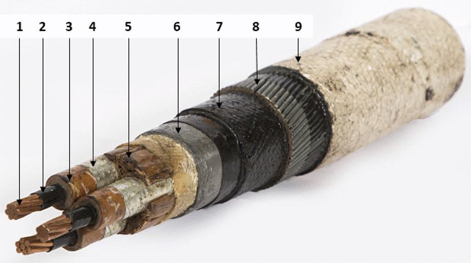
11kV PILC Cable
Cold shrink products such as push-on, pre-stretched tube and grease applied slip-on types also became popular in the 1960s and are still specified by specific electric authorities and utilities for terminating and jointing MV-HV cables.
In the early 1970s polymeric (XLPE) cable types began to emerge in Europe and the UK, mainly on three-core cables, while the USA employed the single-core cable concept at 10kV, 20kV and 35kV medium voltages.
The heat shrink concept began to be employed at this period by the utility companies and has now spread internationally as the preferred method of cable terminating and jointing.
There are many advantages of using heat shrink cable accessories and techniques, such as:
- Wide shrink ratio – one joint/termination kit assembly to cover numerous cable ranges
- Heat concept dries out moisture from the MV HV cables
- Mastic seals are activated by heat so sealants are usually visible at sleeve ends
- They are not size sensitive and can be used on sector-shaped conductors
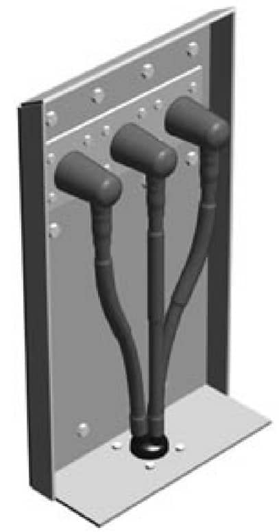
Figure 1 – Cable Box Air Insulated Termination
Cable Joint & Termination Kit Instructions
Shrink Polymer Systems also realised the importance of good cable jointing and terminating instructions. By using pictorial drawings with a minimum of text, non-English speaking countries can identify the important highlighted areas in an easily identified format.

Cable Terminations 11kV 33kV – Instruction Excerpt
Failures are nearly always attributed to poor cable preparation by the jointer and failure to observe the correct jointing procedures in the areas where the electric cable stresses are prudent, such as the semicon screen cut back.
Although the USA shares a language with the UK, there are many differences in the selection of words to describe various things. Below is a list of some UK terminology and the common equivalent used in the United States.
- Core – Conductor
- Screen – Shield
- Joints Jointing – Splice Splicing
- Cable Jointers – Cable Splicers
- Earth Earthing – Ground Grounding
- Armour Support – Reinforcing
- Metal Sheaths – Armour
- Self-Amalgamating – Self-Fusing
Heat Shrink Cable Joints
& Cable Terminations
Terminations
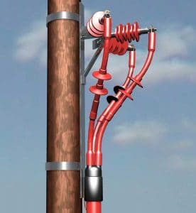
Terminations | Indoor or Outdoor
The major MV HV switchgear and transformer manufacturers have, for many years, designed dry-air filled cable boxes, resulting in a much greater demand for heat shrink-on terminations.
All heat shrink cable terminations and joints have to be tested to various international standards, and while cables prepared by experts in perfect laboratory conditions will undoubtedly meet these requirements under test, field experience shows that failures still occur at working voltage due to a variety of reasons.
Typical List Of Weakness Resulting In Failures
Of Heat Shrink Terminations
- Compression lugs, or crimp lugs, fitted to outdoor terminations of the compression tube type with inspection holes allowing moisture to penetrate the conductor cores.
- Failure to eliminate air pockets on paper-insulated, lead covered (PILC) three-core “belted” cables in the crotch area.
- Core crossing resulting in discharge if cores are too close to each other in an unscreened area at the core cross point. This results in the air “breaking down” electrically at approximately 4kV on an 11kV cable, 6kV on a 24kV cable and 9kV on 36kV cable. The anti-track heat shrink material then begins to erode due to the ionisation of the air, which over time will inevitably cause failure of the cable termination.
- Poor cable preparation, in particular on extruded dielectric types where insufficient care is taken on semiconductive screen removal at the crucial area of the screen cut-off. Cable jointers are generally reluctant to purchase engineered screen removal tools and rely on knives, blades and homemade tools for removal. This can result in cutting through the screen and into the primary insulation, leaving voids which result in the discharge phenomena described in the third item above. Even well-prepared screen removal at the cut-off point can result in a possible void, as the stress control tube may not follow the semi-conductive edge profile. (See figure 2.)
- Moisture penetration due to poor heat shrink and mastic sealing techniques.
- Inadequate phase-to-phase and phase-to-earth clearance.
- Tracking.
- Poor cable jointing instructions.
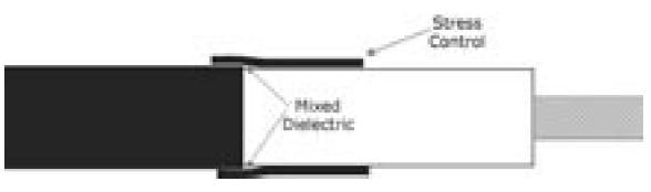
Figure 2
There are solutions and remedies to these weaknesses relating to MV HV cable accessories which will be described later in the article.
Joints
Many of the points discussed regarding cable terminations are also relevant to joints.
The object of the cable jointing exercise is to replace all the materials that were removed to joint the conductors and replace them in such a way as to replicate the cable as closely as possible to its original state.
There are many techniques used in conductor jointing from “sweating” the weak-back ferrule (normally associated with the original cast iron paper joints) to compression and the present popular “shear bolt” designs.
Connector jointing is a complex subject due to the variety of designs for copper and aluminium conductors in circular-solid, circular-stranded, and sector-shaped styles.
There is also the consideration of copper being jointed to aluminium, cables of unequal cross sectional area being jointed to themselves, and transition jointing where paper is being jointed to polymeric at medium or high voltages.

Figure 3 An 11kV 3 Core Heat Shrink Cable Joint
Let’s look at some of these designs.
Compression Connections – Crimps
There are a substantial number of manufacturers, such as Cembre, who specify suitability of their electrical connector design for voltages up to 33kV/36kV. Caution is needed if the body of the barrel is not smooth and does not have tapered ends.
Also, responsible MV HV connector manufacturers will be able to manufacture appropriate crimping tooling for their designs or confirm the compatibility of other cable tooling and die combination for their connectors. There are three types of crimping configurations currently in use: hexagonal, oval, and indent.
For instance, the Cembre HT131-C is the industry standard hydraulic crimping tool used by LV HV cable jointers to install copper type lugs and splices onto stranded cable conductors.
Oval and hexagonal crimping can leave sharp “ears” if incompatible tooling is used.
These “ears” must be filed smooth to avoid a highly stressed area which will be subjected to electrical discharge. Indent crimping will leave void holes which must be filled with high permittivity, stress relief tape.
Mechanical Connections – Shearbolts
Mechanical split type connectors are now very popular in the UK, as this design comes in two halves which are easy to apply to three-core cables at 11kV or 33kV where the cable conductors do not have to be bent. The heads shear-off at a given torque; therefore, no compression tooling or die combinations are necessary.
As this connector is “blocked,” it is also suitable for transition cable jointing for paper to plastic to stop the migration of the paper oils. There are several disadvantages of this type of connector, however. The ends of connector are non-tapered, resulting in high “step downs”, and the conductor insertion is non-centralised. (See figure 4.)

Figure 4 Mechanical Shearbolt Connector
These two conditions result in areas of high electrical stresses leading to probable discharge.
Shrink Polymer systems have now standardised on a shearbolt connector design where these critical areas of high stresses are removed by tapering the ends and centralising the conductor. (See figure 5.)
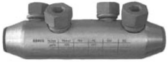
Figure 5 Mechanical Shearbolt Connector (Tapered)
Stress-Relieving Tapes
This type of stress relief tape generally has permittivity values between 7 and 13 (test method IEC 250). (See figure 6.) This does not necessarily mean that a value of 13 will perform better than a value of 7, as void filling characteristics are equally as important.
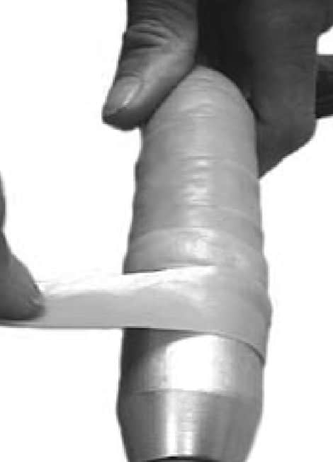
Figure 6 MV HV Connectors & Stree Relief Tape
Shrink Polymer Systems have a yellow stress control tape, reference number TS 31785Y, which possesses high tack, high stretch, and low viscosity void-filling qualities with a permittivity value of minimum 9. Whichever type of cable connector is selected, stress-relieving tape must be used in conjunction with heat shrinkable installations.
This is applied in a half width overlap with stretch by the cable jointer and must also be applied to any indents left by the tooling.
Gaps between end of primary insulation and connector must also be filled in.
Push-on molded components are also widely used, eliminating the need to fill voids and use stress tapes.
They rely on the Faraday Cage principle, in which conductive rubber-ribbed moldings are in contact with the connector. As the potential difference across the air is very low, discharge should not occur. Push- on molded components, joints and terminations have several disadvantages however.
On three-core cables the molded components prove to be very bulky and have no design features to eliminate moisture penetration unless used in conjunction with large diameter shells and resins. On large aluminium conductor sizes the ferrule could possibly be longer than the moulded component. The positioning over the ferrule is critical.
Stress Control Heat Shrink Tubing
Shrink Polymer Systems employ the heat shrinkable, high permittivity, and low resistivity stress control tubing which is shrunk onto the stress relief tape using heat applied by a jointers gas torch previously applied.
This has the effect of achieving a more uniform distribution of the field lines. This heat shrink tube extends over the ferrule or connector and onto the prepared screen cut-off points of the medium/high voltage power cable (See figure 2.)
Insulation Thickness
When designing cable jointing systems, the thickness of the insulation over the bare conductor (i.e. ferrule) should have a safety factor in excess of 15% of the original cable.
Shrink Polymer Systems employ a one-piece, combined dual wall (insulation / semiconductive) heat shrink tube of appropriate diameter to match this insulation at voltages to 11/12kV.
At 17.5kV, 24kV and 36kV additional heat shrink insulation tubes are added to meet these cable specifications.
The cable jointer must remember to shrink this material all around the heat shrink tube to avoid inconsistent wall thicknesses on full recovery.
Typical List of Weaknesses Resulting in Failures
- Incorrect crimping of connector.
- Air trapped in connector (if indent crimps not filled).
- Air trapped between end of insulation and end of connector.
- Discharge at screen ends caused by poor stress taping / cuts to primary insulation.
- Moisture ingress entering cable sheathing through poor sealing.
- Inadequate insulation levels over connector.
- Poor cable termination or cable joint kit instructions.
The solutions and remedies to these weaknesses are described below.
Earthing Cable Terminations
Earthing must be provided to carry any circulating currents to core screens, metal sheaths and armour wires. It must also have the ability to carry fault current. On indoor MV HV cable terminations the use of tin plated copper, solder-blocked braids, metal canisters, armour support, clamps and a complete corrosion protection system should be employed.
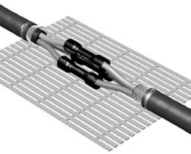
Figure 7 Low Voltage Heat Shrink Cable Joint For Multicore Cables
Earthing Cable Joints
Connecting the earthing components across a heat shrink cable joint requires correctly choosing and fitting the components to take care of both circulating currents and the short circuit requirements.
The outer semiconducting layer of the core/connector insulation should be wrapped in a tin copper mesh bandage and connected to the cable earth at each end.
There are a great many variations and earthing complexities and such a wide variety of cable types to consider.
Once a cable type, size, and voltage are specified it should be left to the manufacturer to supply the correct type of earthing system to meet both the national and local standards.
Remedies & Solutions To Overcome Cable Termination Failures
- Always use one-piece solid lugs for outdoor termination, not squashed tube type.
- Wrap butyl self-amalgamating tape around crotch and under lead cut on three-core belted cables to eliminate air. Check clearance dimensions on three-core cables.
- Care must be taken in semicon screen removal not to nick the primary insulation at the screen cut-off point.
- Ensure all mastic seals are in place on bushing boots, rain sheds and core tubes.
Remedies & Solutions To Overcome Cable Joint Failures
- Ensure cable connector is free from “burrs,” sharp points, not squashed tube type.
- Fill in all gaps with stress tapes before applying stress control tubing.
- Ensure correct application of stress tape at screen cut-off points. (See figure 2.)
- Fit all seals as supplied, in particular at crotch area, under armour beddings and end of connector insulations.
Cable Jointing & Terminating Instructions
It is the responsibility of cable accessory manufacturers to supply easy-to-read, simplified, pictorial jointing instructions and to avoid heavy reading of text manuals.
This point cannot be overstated, as, in the writer’s opinion, far too many jointing instructions are not read or understood, resulting in the installer compromising on the areas of importance previously mentioned. This all too often results in that first failure.

How Can We Help?
Since 1985 Thorne & Derrick have been servicing the UK and Export market with Joints, Terminations & Connectors for LV MV HV cables and power systems – call us to discuss your requirements including specialist LV cable joints for high performance applications including hazardous areas, marine and offshore cables, fire resistance cables and low smoke zero halogen cables.
Thorne & Derrick
Key Product Categories: Duct Seals | Cable Cleats | Cable Glands | Electrical Safety | Arc Flash Protection | Cable Jointing Tools | Cable Pulling | Earthing | Feeder Pillars | Cable Joints LV | Joints & Terminations MV HV

HV Cable Joints & Cable Terminations | Heat Shrink | 6.6kV 11kV 33kV Cables
3M Scotchcast Cable Joints – Your Cable Circuit Is Only As Strong As Its Weakest Link
May 25th, 2018
3M Scotchcast Resins – Powerful Cable Joints
uploaded by Chris Dodds - Thorne & Derrick Sales & Marketing Manager
Selection Factors, Specification Considerations & Application Notes
Why Gamble With Your Power Supply By Installing Underspecified Cable Joints?

A Failed Cable Joint
Since 1985, Thorne & Derrick International, have stocked and distributed 3M Scotchcast cable joints renowned for their field service record and dependability for the connection and repair of existing damaged cables or the extension or diversion of new cable installations.
Whether XLPE, EPR, PILC or other cable type, Scotchcast joints are the preferred option for LV power, instrumentation or control cables.
The primary purpose of any LV cable joint is to remove a damaged or faulted section of cable and re-instate the electrical performance of the jointed cable as closely as possible to the original manufactured condition.
The specification, selection and installation of Low Voltage Resin Cable Joints varies according to industry. So, without a universal methodology the selection factors are usually specific to the cable and industry. Several key factors include : cable function, cable reliability, installation application and consequential loss due to outage or downtime.
Standard resin cable joints are often inadvertently installed forming weak links in many industrial cable networks.
Scotchcast Joints
Whether by Land, Air or Sea
3M Scotchcast resin cable joints provide reliable and safe performance in the construction, rail, renewable, airfield lighting, port authority, offshore, marine, mining, utilities and hazardous area (oil, gas and petrochem) industries.
“Scotchcast” has now become a byword for cable joints.
Scotchcast resins are synonymous with reliability, quality and dependability when jointing cables, whether above or below ground – a comprehensive range of jointing resins have been developed by 3M with fire resistance, flame retardant, low smoke zero halogen and hydrocarbon resistant performance.
Deep Underground
3M Scotchcast 82-F cable joints are specified for the straight and branch jointing of flexible mining and trailing cables. Utilising flame retardant and flexible 3M Scotchcast 2131 resin with Mine Safety and Health Administration (MSHA) Acceptance 07-KA060002-MSHA.
3M 82-F flexible cable joints do not impair the bend radius of frequently coiled cables – the submersible cable joints are also seawater resistant for connecting cables by divers to ROV (Remotely Operated Underwater Vehicles).
♦ Further Reading : Top 10 Deepest Mines In The World

Seeing Beyond The Surface – Worker & Site Safety With 3M Cable Joints

The World’s Biggest Coalmine : Peabody Energy’s operations in the Powder River Basin of Wyoming USA. 40% of America’s coal comes out of the North Antelope Rochelle Mine. Photograph: Mae Ryan for the Guardian
Offshore Cable Joints
3M Scotchcast resin cable joints are specified by the global oil and gas exploration companies for the low voltage jointing of power, instrumentation and control cables.
3M LVI3 resin cable joints suit offshore and marine power, instrumentation and control cable (BS6883, IEEE, UL, UK00A, NEK606 BFOU RFOU types) and instrumentation cable (pair, triple, quad types) – typically used to joint and connect cables in Zone 1 and Zone 2 hazardous areas to provide low voltage electricity distribution to power and lighting in potentially explosive atmospheres.
3M LVI3 joints are hydro-carbon resistant based on the specification performance of 3M Scotchcast 1402FR and resist degradation by drilling fluids (mud) – the ability of offshore topside and shipboard cable joints to withstand degradation by hydro-carbons and drilling MUD is vital avoid potential cable faults.

3M : Specified By Global Oil & Gas Industry
Repairing Damaged Cables
Cable damage is common offshore due to the extreme mechanical conditions caused by vibration, shock and movement on oil and gas platforms.
Overtime, EPR type rubber cable sheaths are degraded and complete cable change-out can be cost prohibitive or actually impossible.
3M LVI cable joints provide an excellent cable repair or full cable joint to damaged offshore cables preventing possible downtime caused by cable failure due to salt sea atmospheres reacting with cable braiding and conductors and causing a short circuit.
The wrap-around or snap-on 2 part type cable joint moulds permit mid-span cable repairing or jointing without requiring cable disconnection from the remote end – refer to our recent post about repairing damaged cables for further information and solutions including use of cold shrink tubes.

3M Cable Joints are installed on offshore oil and gas platforms, FPSO’s, FPS’s, oil tankers and carriers
With You In The Cable Trenches

Image : Lovink.
Bent double in a muddy hole in the ground wrestling with a post-war imperial PILC cable.
And if you’re cable jointing in the UK then it’s probably raining.
We know the score. Hence, 3M cable joints are designed by jointers for jointers.
Large shell 3M cable joints enable crimping tool access or mechanical shearbolt connector compatibility for simplified cable jointing in tight access cable trenches and cable containment.
Cross core and transition cable jointing of multi-core XLPE to PILC is enabled.
Strong impact resistant cable joints shells withstand trench backfill. Often sand backfill can be mixed with sharp stones, clay and organic detritus.
3M can cope.
Size Matters
The internal working space permitted by the cable joint shell design impacts upon the ability of the LV cable jointer to work comfortably and safely often in tough site conditions.
Ample work-room enables efficient and reliable armour bonding, cross-core jointing, transition jointing and conductor connecting.
Large cable jointing shells enable the use of mechanical shearbolt connectors, such as Pfisterer Sicon, ideal for imperial-metric-AWG connections and hydraulic crimp tool heads where close quarter working is needed.
Is The Cable Joint Shell Large Enough For The Crossing Of Phased Cores?
Whatever the Weather
Cable damage is common offshore due to the extreme mechanical conditions caused by vibration, shock and movement on oil and gas platforms. Challenging offshore weather conditions vary from brutal hurricanes in the Gulf of Mexico to violent Atlantic nor’easters.
Closer to home, the North Sea UK continental shelf regularly experiences violent Force 10 storms inflicting extreme wind and wave effects on offshore assets.
3M Scotchcast Standing Out From The Crowd
3M Scotchcast low voltage cable joints are designed to ensure the installation process is simpler, quicker and safer.
Some selection and specification considerations :
- Safety – 3M’s unique Advanced Delivery system provides integrated resin pour for the cable jointer eliminating vapour inhalation or direct skin contact
- Simplicity – one part, wraparound cable joint shell enables rapid installation. Reduced man-hours cuts installed cost and drives labour productivity gains often during tight time schedule shutdowns
- Reliability – eliminate or minimise cable faults
Specify and buy 3M Scotchcast cable joints for first class safety and service record without any hidden dangers.

3M Scotchcast Resin Advanced Delivery
Just How Do 3M Do It?
- Single Piece Cable Joint Mould Shell – simpler installation process for the cable jointer. No cutting or sawing cable mould to size. Range taking foam seals at the ends of the cable joint shells provide an excellent tight and reliable seal – this adaptable 3M cable sealing system eliminates the need for the cable jointer to cut and tape the joint shell to size. Folding cable mould meets at the top of cable joint, not along both sides reducing potential resin leakage paths. 3M cable joint moulds resist cracks or breaks even at low temperatures. Suitable for direct burial.
Why Don’t I Need To Cut 3M Cable Joint Shell To Fit The Cable?
- Earthing – 3M’s robust armour continuity earthing system suits both wire armoured (AWA single core and SWA multi-core), wire braided (copper and phosphur bronze) and lead sheathed cables. To avoid awkward manipulation of armour wires while trying to fit worm drive clips over the cable support rings, 3M have chosen to use constant force springs for earthing. Constant force springs offer significant advantages over “single wire type” earth continuity systems, which can fail if poorly positioned within wire armour cores that have “spread”. The flat soft copper earth braid ensures good electrical contact.

Safe & Sound With Constant Force Springs : Cable joints move and expand due to earth shift and heat from electrical current. Constant force springs react to this movement and maintain a sound electrical connection between the steel wire armouring and the earth continuity braid
- Mechanical Connectors – fast, simple and range-taking conductor jointing of copper and aluminium conductors, whether stranded, sectoral or solid. Suits jointing of metric, imperial and AWG conductors.
- Resins – high quality cable jointing resin with good moisture resistance and always enough in the joint kit for the application. No need for “topping-up”.
- Scotchcast 1402FR Resin, Halogen Free – for public areas where fire, smoke and toxic fumes potentially threated lives and equipment
- Scotchcast 1402FR Resin, Hydrocarbon Resistant – suit air exposed and contaminated ground installations
- Scotchcast 2131 Resin, Seawater Resistant – salt water solution resistant to ISO 175
Did You Know?
3M Scotchcast resin cable joints, typically used for 600/100 volts cables, can be up-rated for 3.3kV cable jointing.
3M Scothcast Premium Low Voltage Inline Resin Cable Joint
THORNE & DERRICK SPECIALIST ELECTRICAL DISTRIBUTOR
LV ♦ MV ♦ HV
T&D distribute the most extensive range of LV, MV & HV Cable Jointing, Terminating, Pulling & Installation Equipment – we service UK and international clients working on underground cables, overhead lines, substations, switchgear and electrical construction at LV, 11kV, 33kV and EHV transmission and distribution voltages.
- Key Products: MV-HV Cable Joints & Terminations, Cable Cleats, Duct Seals, Cable Transits, Underground Cable Protection, Cable Jointing Tools, Feeder Pillars, Cable Ducting, Earthing & Lightning Protection, Electrical Safety, Cable Glands, Arc Flash Protection & Fusegear.
- Distributors for: 3M, ABB, Alroc, Band-It, Catu, Cembre, Centriforce, CMP, Elastimold, Ellis Patents, Emtelle, Furse, Lucy Zodion, Nexans Euromold, Pfisterer, Polypipe, Prysmian, Roxtec.

LV – Low Voltage Cable Joints, Glands, Cleats, Lugs & Accessories (1000 Volts)

MV HV – Medium & High Voltage Cable Joints, Terminations & Connectors (11kV 33kV EHV)

Cable Laying – Underground Cable Covers, Ducting, Seals & Cable Pulling Equipment
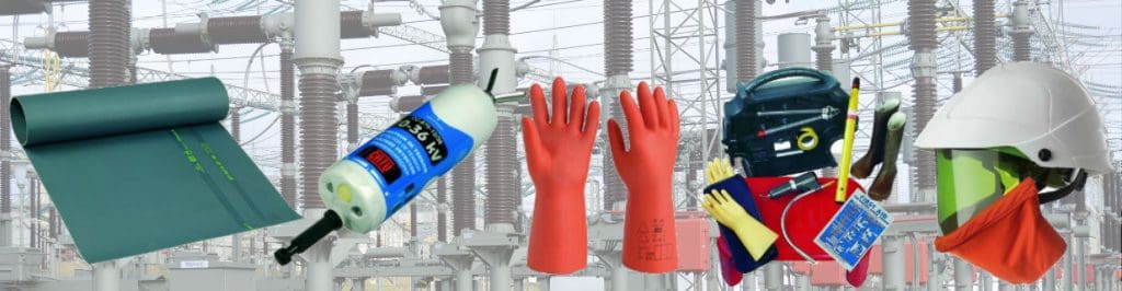
T&D, CATU Electrical Safety & Arc Flash Protection Specialists for SAP’s, Linesmen, Jointers & Electrical Engineers – Largest UK Stockist
INVITATION
Thorne & Derrick invite you to join LinkedIn’s largest LV-HV Electrical Discussion Group : Low & High Voltage Power, Cabling, Jointing & Electricals. Discussion subjects include cable installations, cable jointing, substation, overhead line and electrical construction at LV, 11kV, 33kV and EHV. Network, engage and promote your profile, company or products with over 10,000 influencers.


How To Install 3M Cold Shrink Cable Joints (LV)
May 18th, 2018
A series of How-To videos for repairing, jointing and terminating cables using 3M Cold Shrink & Scotchcast products.
Cold Shrink Cable Joints
This video by 3M Electrical shows how to apply 3M Cold Shrink Cable Joints safely to splice, repair and connect low voltage power cables, 600V/1000V.
3M Cold Shrink cable joints utilise tool free cold shrink technology where no heat or gas torch is required for jointing cable in onshore and offshore locations with polymeric type cable insulation construction including both XLPE and EPR.
Cold shrink is an effective alternative to resin cable joints and can be used indoors, outdoors, overhead or used in cable trays.
Jointing Cables
Ensure all cables and conductors are free from dirt, residue and contaminants using cable cleaning wipes prior to preparing the cable to install the joint.
Cold shrink tubes and copper wire sleeves are first positioned over the cable.
The cable cores are then cut in such a way to stagger the position of the connectors – either mechanical shearbolt or crimp splice connectors are compatible. Check the proposed conductor connector is of suitable physical dimensions to be used with the cold shrink joint – on larger conductors due to volume displacement of multiple mechanical type connectors it maybe preferable for the jointer to use crimp/compression splices due to smooth profile design overcoming any potential bulging or distortion of the cold shrink tubes.
Accepted brands include Cembre, Arcus and Pfisterer Sicon type connectors.
The cable insulation is then removed and connectors are installed.
Most connector technology can be used providing they suit the requirements of the cable voltage, conductor construction and fit dimensionally within the 3M cable joint.
Scotch Electrical Tapes
Scotch 23 self-amalgamating tape is used to over tape the connectors. Layers of Scotch 23 are applied tightly around each connector overlapping into the primary insulation on each side of the connector position.
A piece of cable jacketing that has been saved from the cable preparation is then wrapped around the connectors for added mechanical protection.
Scotch 2228 mastic tape is then used to seal the crotch of the cable.
Scotch 33+ premium insulation tape is applied across the lengths of the cold shrink joint to improve electrical insulation and water sealing protection.
The copper wire sleeve is then repositioned over the joint and secured onto the cable armours (either wire or braid armour) with constant force springs providing a 360º earth screen around the cold shrink cable joint for added protection.
Scotch 23 self-amalgamating tape is used to tape over the constant force springs ensuring the application is in the same direction as the constant force springs.
Scotch 2228 mastic tape is wrapped over the constant force springs to ensure a smooth profile and to achieve the required cable seal.
The 3M cold shrink protection tube is then positioned over the cable joint. The coil is then removed by hand to install. The live memory action of the specially formulated material shrinks the cold tube into position and ensures a constant radial pressure and seal.
Cold Shrink Joints Selection Table For Power Cables
Selecting the correct 3M LC type cable joint for use with single and multi-core type power cables, typically BS5467 (SWA) or BS6883 (GSWB).
| Cold Shrink Joint Part Number | Cross Sectional Area (mm²) | Cable Diameter Range (mm) | Cable Armour Range (mm) | ||||
| Single Core 1kV | Two Core 1kV | Three Core 1kV | Four Core 1kV | Three Core 3.3kV | |||
| 3M LC1 | N/A | 1.5 – 4 | 1.5 – 4 | 1.5 – 2.5 | N/A | 16.1 – 33.1 | 9 – 15 |
| 3M LC2 | 50 – 95 | 6 – 10 | 6 – 10 | 4 – 6 | N/A | 16.1 – 33.1 | 14 – 22 |
| 3M LC3 | 120 – 150 | 16 – 50 | 16 – 25 | 10 – 16 | N/A | 16.1 – 33.1 | 18.5 – 29 |
| 3M LC4 | 185 – 400 | 70 – 120 | 35 – 70 | 25 – 50 | 16 – 50 | 24.9 – 56.4 | 23.5 – 37 |
| 3M LC5 | 500 – 630 | 150 -185 | 95 – 150 | 70 – 120 | 70 – 150 | 37.8 – 84.3 | 31 – 50 |
| 3M LC6 | 800 – 1000 | 240 – 300 | 185 – 240 | 150 -185 | 185 – 240 | 37.8 – 84.3 | 44 – 70 |
| 3M LC7 | N/A | N/A | 300 | 240 – 300 | 300 | 62.5 – 128.5 | 44 – 70 |
Cold Shrink FAQs
Can 3M Cold Shrink Joints Be Resin Encapsulated?
Standard 3M Cold Shrink cable joints in the LC range can be over-protected by using cable joint moulds and then filled by pouring resin into the mould to encapsulate the joint – for example the cold shrink joint can be modified to provide resistance to hydrocarbon damage in hazardous area locations by using 3M Scotchcast 1402FR resin.
Can 3M Cold Shrink Joints Be Used To Joint Halogen Free & Flame Retardant Cables?
3M cold shrink joints can be used in conjunction with 3M STFF outer-protection sleeve – the joint sleeve is designed to protect the joint from fire. STFF sleeve is halogen free/zero halogen, flame retardant and does not emit toxic fumes in fire situations. Specified for onshore, offshore and rail tunnel applications where fire resistant protection of the cable joint is critical to overall performance, safety integrity and operational fire performance of the electrical cable and power system.
Can 3M Cold Shrink Be Used For Cable Repair?
Where cables have been subject to sheath degradation overtime due to electrical and mechanical stresses whilst in service a cold shrink tube can be used to re-instate the levels of cable insulation – note this requires access to an open-end of the cable or disconnection of the cable due to the tubular design of the cold shrink. If disconnection or isolation of the power cable system is not possible a heat shrink wrap-around type cable repair can be carried out. Read more about this subject in our detailed Blog covering solutions for repairing damaged cables.

Cold Shrink – invented by 3M over 40 years ago and now the preferred technology for heat-free jointing, terminating, sealing and abandonment of LV HV cables
We hope you find this video informative and educational, contact T&D for technical support, quotations and stock availability for 3M Low Voltage Cold Shrink Cable Joints.
➡ Visit 3M Electrical for further information about joints, terminations, tapes and insulation to seal, repair, splice and connect LV MV HV cables.
Learn more about the benefits and applications of Cold Shrink:

Cold Shrink | Joint | Terminate | Seal | Repair | Splice | LV MV HV Cables | 3M
- 3M Electrical Products Stocked By Thorne & Derrick International
UKPN Cable Jointers Required | Immediate Start | Long Term Contract | Apply Now
May 17th, 2018
Contract: UKPN Network | Immediate Start
Work Type: Installing Service Termination Heads (Cut-outs ) 80- 100A
Posted By
Jordan Hamer (Recruitment Consultant at Cordant Group PLC / Utilities G.W.E.T)
My client is a successful infrastructure business offering services to the power, water, gas, rail, telecommunications and infrastructure sectors.
They have depots in Leicestershire, North London, Kent and Magherafelt.
Due to the acquisition of large contracts with DNO’s they have a large recruitment drive in progress and are recruiting teams of cable jointers for the duration of the UKPN project.
Role Outline
The Cable Jointers will be required to work in teams of 2 (Cable Jointer + Jointers Mate).
They will perform cut-outs across the M25 corridor and will be targeted to do 25 per week.
Any cut-outs completed after the 25, will be paid at £65 per cut off per jointing team.
Applicant Requirements
Jointers must have UKPN Authorisation (any area) – the successful applicants will be prepared to travel, hold EUSR Card and carry own tools.
Benefits
£500 per day per Jointing team
£65 bonus per Jointing team per cut off
Ongoing long term work up to 4 years
Immediate starts
What Next?
To apply for this role or if you would like to discuss in more detail please contact me directly or apply with an up to date CV:
Jordan Hamer | Contracts Consultant
Cordant Recruitment
No 1 St James Square, Manchester M2 6DN
t 0161 8311608
m 07757 674 066

Who Are Cordant Engineering?
At Cordant Engineering we research all aspects of low, medium and high voltage power generation, transmission and distribution, as the demands of power networks continue to grow across the UK.
A wide variety of problems can affect power anywhere and at anytime but it is by providing specialist engineering skills that consequently minimise problems encountered.
Therefore, we aim to support our clients to guarantee safe and reliable operation of LV MV HV electrical power systems today and in the future.
We have the expertise and capability to work with a range of businesses concerned with T&D, power generation, substation service and maintenance.
Staff and contractors are provided for everything from 11kV-33kV private network services to 132kV-400kV turnkey projects for all medium/high voltage cabling projects.
Our expertise covers a range of specialised sub-sectors including:
- 11kV 400kV Substation Services
- LV 400kV OHL Maintenance, Construction & Surveys
- LV 33kV Asset Replacement
- Underground Network Services
- Vegetation Management
Typical Roles
- Linesmen
- Cable Jointers LV MV HV
- Project Managers
- Site Engineers / Managers
- Planners
- Design Engineer
- Operations Manager
- Senior Authorised Person
- Quantity Surveyor
- Patroller

Watch, Listen & Learn About The Cordant Group
Thorne & Derrick
Product Categories: Duct Seals | Cable Cleats | Cable Glands | Electrical Safety | Arc Flash Protection | Cable Jointing Tools | Cable Pulling | Earthing | Feeder Pillars | Cable Joints LV | Joints & Terminations MV HV
We distribute and supply from stock LV, MV & HV Cable Joints, Terminations, Substation & Electrical Equipment from our Key Suppliers including:
| 3M | CMP | Ellis Patents |
| Nexans Euromold | Elastimold | Pfisterer |
| Prysmian | Alroc | CSD |
| Roxtec | CATU Electrical | Cembre |
| Lucy Zodion | ABB | Emtelle |
Thorne & Derrick – Stockists & Suppliers of MV HV Joints, Terminations & Connectors
Underground Cable Photo Album 1890-1940 – Western Power Distribution (WPD)
May 15th, 2018

-
uploaded by: Chris Dodds - Thorne & Derrick Sales & Marketing Manager
Electricity history courtesy of the Western Power Electricity Historical Society UK – photographs of pulling, laying and jointing LV up to 33kV cables from yesteryear.
Peer into the past to a time when dapper, bowler-hatted and waistcoated Cable Gang Managers attired in three piece suits oversaw the hand pulling of cables into trenches worked by Jointers in cloth caps, trouser braces and brogues.
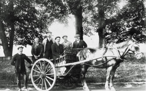
The first picture is poignant, The Cable Gang.
Workmates Tom, Arthur and Albert carted up and ready for a day in the cable trench.
It’s 1915 and the First World War is raging across Europe. No doubt the Gang would have friends and family in an altogether different type of trench somewhere along the muddy and bloody Western Front.
The Cable Gang – a cable jointing gang in Shirehampton Road. Bristol. Tom Webb was in charge of driving cart, tall man is Arthur Attwood and on the extreme right is cable jointer Albert Keepin (1915).
Cable Laying – power cables being manually pulled from cable drums and laid underground at High Street/Back of Bridge Street, Bristol (1898).

Cable Protection – Baldwin Street cable works with cable protection covers and markers made from brick, Bristol (1893).

Cable Pulling – electric power cables being laid into cable trench from The Strand to Beacon Quay electricity works Devon, Torquay (1897).

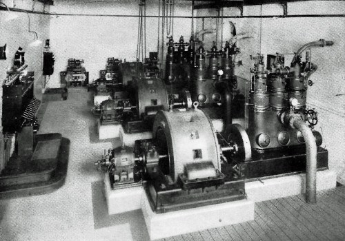
Power Rectifiers – three Willans steam engine/Easton Anderson alternators with three Ferranti rectifiers in background. Devon, Torquay (1898).
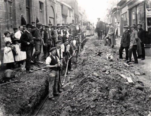
Cable Jointing – Baldwin Street, near Bristol Bridge. Mr J Duggan behind cloth capped gentleman on left. Note bricks with circuit description (1900).

Trimming Team – arc lamp maintenance and trimmer team. Bristol (1904).
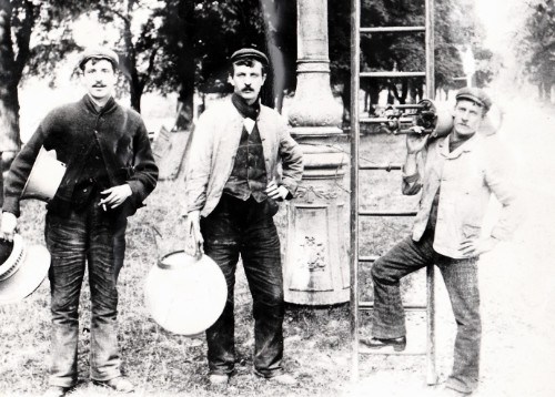
High Voltage Jointing – 10kV 0.4 PILC high voltage cable in Mannesman tubes and low voltage cables in a bunch. Cornwall, Causewayhead, Penzance (1912).
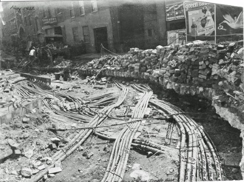
Cable Diversions – Temple Back from Half Penny Bridge direction. On the photograph, the cables have been identified in ink. Bristol, Temple Back (1914).
Cable Works – extensive cable works in Temple Back facing Phillip Street. On the photograph, the cables have been identified in ink. Bristol, Temple Back (1914).
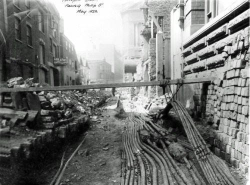
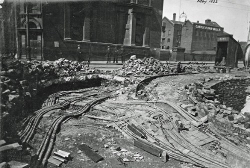
Cable Diversion – cable diversions from Temple Back adjacent to Half Penny Bridge. On the photograph, the cables have been identified in ink. Bristol Tramways and Carriage Power Station opposite and Castle Flour Mills across bridge in background (1914).
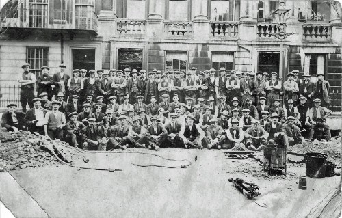
Cable Jointers – some cable jointers and workmen involved in the single to 3 phase changeover photographed in Vyvian Terrace. Bristol, Clifton (1921).
Power Cables – delivery of Henley cables. Small van of Cornwall Electric Power Company (1927).

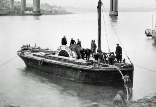
33kV Cables – submarine cable from Saltash to Devonport being installed. Devon, Torpoint (1931).
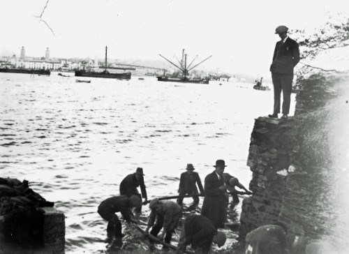
33kV Cables – Devonport to Saltash 33kV power cable crossing. Barge with high voltage cable on Devonport shore (1931).
33kV Cables – cable laying and jointing 33kV cables from Portishead Generating Station across River Avon (to Avonmouth). North Somerset, Portbury (1934).
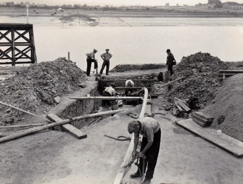
33kV Cables – laying 33kV cables from Portishead Generating Station between Avonmouth Dock and Avonmouth. Bristol, Avonmouth Dock (1934).

Laying 33kV Cables – from Portishead Generating Station between Avonmouth Dock and Avonmouth at River Avon crossing. Avonmouth Dock high voltage cables being greased before being pulled through pipes across River Avon (1934).
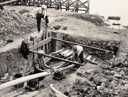
33kV Cables – 33kV Callenders submarine cable passing through Barnstaple. Devon, Barnstaple (1934).

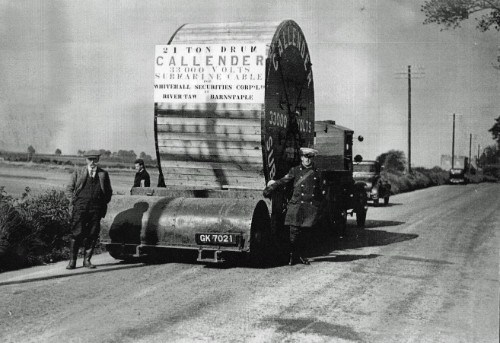
33kV Cables – River Taw crossing. 21 ton drum of Callender 33,000kV submarine cable for Whitehall Securities Corp. Ltd. View of cable drum on special low loading wagon. Devon, Barnstaple (1935).
Thorne & Derrick Working With Western Power Distribution
Today Western Power Distribution (WPD), is the electricity distribution network operator for the Midlands, South Wales and the South West.
Electricity is conveyed countrywide via the National Grid at 275kV or 400kV – the EHV (Extra High Voltage) power is reduced to 132kV for regional distribution at high voltage substations known as Grid Supply Points. From there the power is distributed to further electricity substations via overhead lines or underground cables at 132kV. The voltage is reduced again to 33kV and then to 11kV by medium voltage transformers.
This power distribution network then carries electricity to individual towns and villages throughout the Midlands, South West and Wales where distribution substations transform the voltage to low voltages (230 volts).
WPD network is comprised of over 220,000 kilometres of overhead lines and power cables and 185,000 transformers which are used to step down voltages. These medium/high voltage transformers vary in size from large units capable of supplying an entire town, to tiny ones serving isolated remote cottages.
Since 1985, Thorne & Derrick have been proud to supply and support WPD with an extensive range of LV, MV & HV Jointing, Earthing, Substation & Electrical Eqpt.
Headquartered in Bristol, Thorne & Derrick’s home DNO is WPD.

Specialist Distributors: LV, MV & HV Cable Jointing, Substation & Electrical Eqpt
THORNE & DERRICK are national distributors of LV, MV & HV Cable Installation, Jointing, Duct Sealing, Earthing & Electrical Equipment – we service UK and global businesses involved in cable installations, cable jointing, substation, overhead line and electrical construction at LV, 11kV, 33kV and EHV.
Contact us for 3M Electrical, ABB, Alroc, AN Wallis, CATU Electrical, Cembre, Centriforce, CMP, CSD, Elastimold, Ellis Patents, Emtelle, Euromold, Filoform , Furse, Lucy Electric & Zodion, Nexans, Pfisterer, Polypipe, Prysmian, Roxtec, Sicame, WT Henley.

Specialist Distributors Of LV MV HV Jointing, Cabling & Electrical Equipment


