Schneider Gas Insulated (SF6) Switchgear, RMU’s & MV Medium Voltage Electrical Equipment
Uploaded by Chris Dodds – reading time 8 minutes
Switchgear Bushings & Cable Connectors
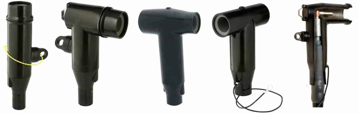
The following information has been provided to enable to correct selection and specification of MV Bushings and Separable Connectors used to connect and terminate medium/high voltage power cables into Schneider RM6 gas insulated switchgear and Ring Main Units (RMU) up to 24kV.
General
The profiles, contacts and dimensions of the Schneider RM6 connection interfaces are defined by the IEC 60137 standard
100% of the epoxy resin interfaces undergo dielectric testing at power frequency and partial discharge tests
Insulated connectors must be used in order to guarantee the dielectric performance
Appropriateness For Use
Types of Connection Interface
The bushings carry the electrical current from the outside to the inside of the MV switchgear enclosure, which is filled with SF6 gas, ensuring insulation between the live conductors and the frame for MV power distribution.
There are 3 types of MV bushing, which are defined by their short-time withstand current:
Type A Interface Bushing: 200 A: 12.5 kA 1 s and 31.5 kA peak (plug-in)
Type B Interface Bushing: 400 A: 16 kA 1 s and 40 kA peak (plug-in)
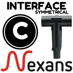
Type C Interface Bushing: 630 A: 25 kA 1 s, 21 kA 3 s + 62.5 kA peak (disconnectable M16)
➡ For further information on Euromold Connectors for all other Interface Bushings up to 66kV please see the following information:
The Euromold brand of MV Cable Connectors manufactured by Nexans for 11kV 33kV 66kV connection of medium/high voltage power cables into gas insulated electrical equipment.
How To Define The Cable Connectors Interface
The connection interfaces depend on specific criteria, such as:
Installation
Current rating of the connected equipment: 200, 400, 630 A
Short-time withstand current for 12.5 kA, 16 kA, 25 kA switch and circuit breaker functions
For the fuse-switch combination function, as the short-circuit current is limited by the fuse, the connection interface will be of type A (200 A)
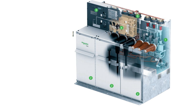
Stainless steel tank filled with SF6 gas, sealed for life and containing the medium voltage (MV) busbar and all live switching components such as the switch-disconnector, earthing switch, the fuse switch combination or the MV circuit breaker
One of the five cable compartments with interfaces to connect to the network or medium voltage transformer
User interface with single line diagram, actuators and LV components
Manual or motorised operating mechanism compartments
Single-core cable, paper impregnated, non-draining type
Performance
Cable Termination
Manufacturer
Cable Termination Reference
Cross Section sqmm
Comments
7.2 to 17.5 kV630 A-95 kV impulse
Insulating Bushing Boots
ABB Kabeldon
SOC
25 to 300
Simplified Disconnectable
Tyco Electronics
RICS – EPKT
25 to 300
Heat Shrink Cable Termination
Tyco Electronics
EPKT+EAKT+RSRB
95 to 300
24 kV630 A-125 kV impulse
Simplified Disconnectable
Tyco Electronics
RICS – EPKT
25 to 300
Non-directed field disconnectable connector
Three-core cable, paper impregnated, non-draining type
Performance
Cable Termination
Manufacturer
Cable Termination Reference
Cross Section sqmm
Comments
7.2 to 17.5 kV630 A-95 kV impulse
Insulating Boots
ABB Kabeldon
SOC 630
25 to 300
Simplified Disconnectable
Tyco Electronics
RICS – EPKT
25 to 300
Heat Shrinkable Termination
Tyco Electronics
EPKT+EAKT+RSRB
16 to 300
24 kV630 A-125 kV impulse
Simplified Disconnectable
Tyco Electronics
RICS – EPKT
25 to 300
Disconnectable Connector Single-core Dry Cable &
MV Medium Voltage Lightning Arrestor
Performance
Cable Connection
Manufacturer
Cable Termination Reference
Cross Section sqmm
Comments
7.2 to 17.5 kV630 A-95 kV impulse
Disconnectable
nkt cables GmbH
AB 12-630 + ASA12(5 or 10 kA)
25 to 300
Non-directed field
CB 24-630 + CSA 24(5 or 10 kA)
25 to 300
Directed field
24 kV630 A-125 kV impulse
Disconnectable
nkt cables GmbH
AB 12-630 + ASA12(5 or 10 kA)
25 to 300
Non-directed field
CB 24-630 + CSA 24(5 or 10 kA)
25 to 300
Directed field
7.2 to 17.5 kV630 A-95 kV impulse
Disconnectable
Tyco Electronics
RICS+EPKTRDA 12 or 18
25 to 300
Elastimold | Euromold
K400TB + K400RTPA+ K156SA
35 to 300
Cable box enlarged
24 kV630 A-125 kV impulse
Disconnectable
Tyco Electronics
RICS + EPKTRDA 24
25 to 300
Elastimold | Euromold
K440TB + K400RTPA+ K156SA
35 to 300
Cable box enlarged
Tyco Electronics
RSTI-58 + RSTI-CC-58SAxx05
25 to 300
Directed field 5 kA arrestor
Tyco Electronics
RSTI-58 + RSTI-CC-66SAxx10M16
25 to 300
Directed field 10 kA arrestor
See How Thorne & Derrick & Nexans Euromold can support your MV Bushings & Connectors requirements
Thorne & Derrick International
Since 1985 Thorne & Derrick based in the UK have been specialist distributors of LV, MV & HV Cable Installation, Jointing, Substation, Arc Flash Clothing & Electrical Safety Equipment – customers include UK and worldwide contractors, specifiers, traders and end-users involved in medium and high voltage cable installations, cable jointing, substation, overhead line and electrical construction.
by Chris Dodds T&D - estimated reading time 5 minutes
MV Joints & Cable Preparation
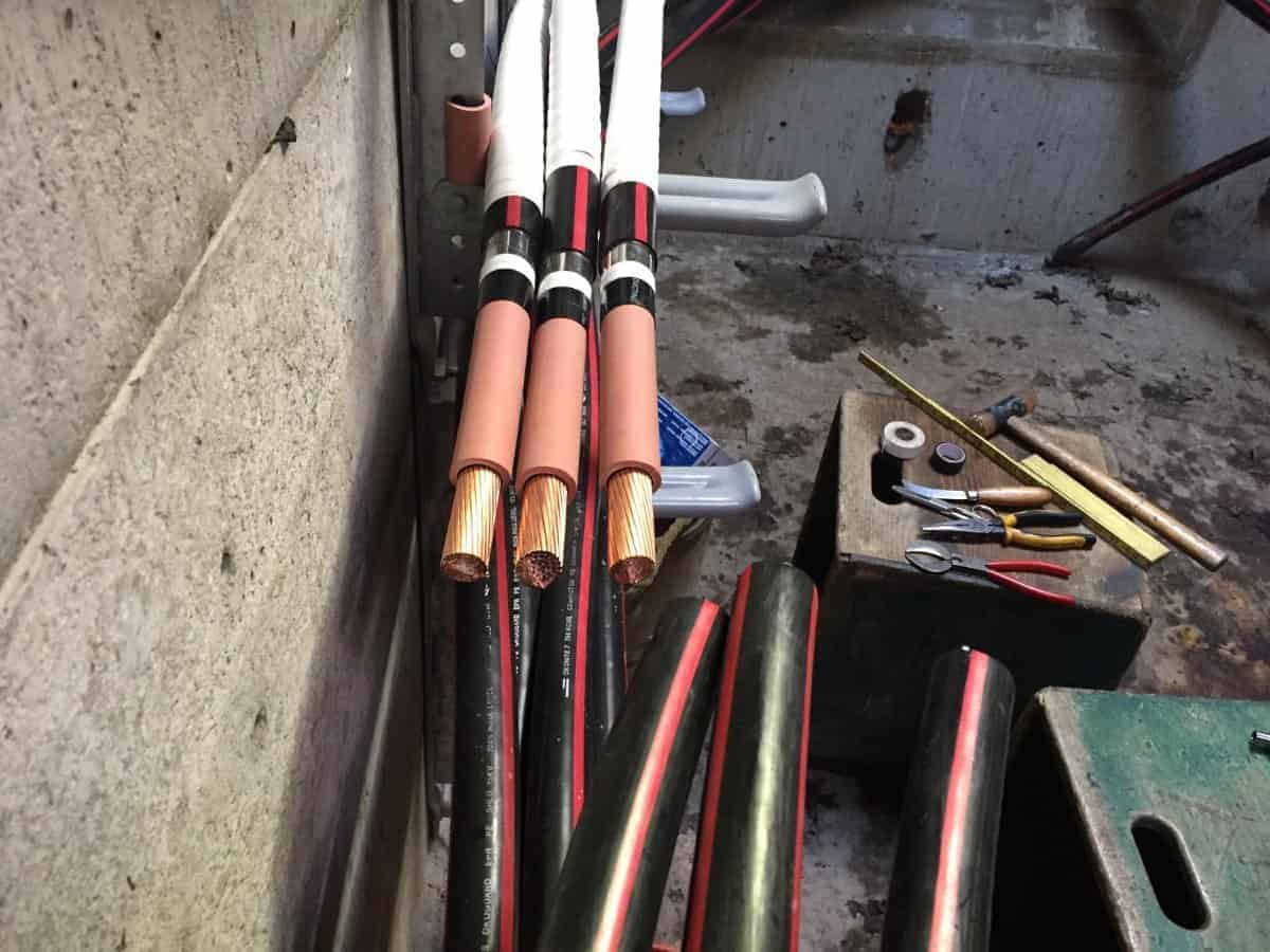
1. MV Cable Preparation. The medium voltage cables are expertly prepared by the cable jointer/splicer using basic tools such as cable jointing knife, needle nose pliers and a scale ruler – no specialist cable jointing tools were used to complete this MV cable preparation or joint. To achieve this level of precision and accuracy without damaging the cable and jeopardising the medium voltage cable joint requires an exceptional skill level. The 15kV cable manufactured by Okonite is 750 KCMIL with EPR insulation and ready to be connected using Prysmian cable joints. The white tape overlap section between the copper tape screen and semicon screen is used to secure the medium voltage cable shielding in place.
2. Medium Voltage Cable Joints – Fire Proof. The medium voltage cable joint is over-wrapped to provide fire protection and arc proofing. This MV cable joint was for a new medium voltage circuit with several cable chambers so the 15kV cable is actually open on both ends and not grounded – “the phasing is not completed until every medium voltage cable joint or splice is completed except the first and last, and that’s when we phase it,” comments Christopher.
3. Medium Voltage Straight Joints – no tee (or branch) cable joints were installed, “this particular MV circuit isn’t very long and goes from substation to a dozen or so manholes, then the medium voltage cable terminates at a riser. If our circuit has wyes or tees, we still typically phase at the end,” added Christopher. Branch joints can be used to split main feeder cables into two cables that can be directed to other loads.
Cable Pulling– the cable gang pulling 15kV 500MCM medium voltage EPR cable. Here the contractor is preparing to piece out a circuit that runs through the middle of the manhole (cable splicing or jointing chamber).
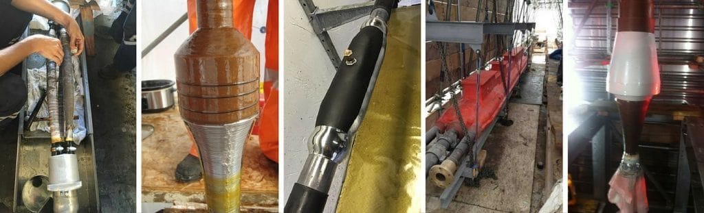
Prysmian Elaspeed Cable Joints
Prysmian Elaspeed cold shrink cable joints and splices are medium voltage cable accessories extensively specified in North American markets – Elaspeed are not molded cable joints. Elaspeed cable joints feature a core constructed from ethylene propylene rubber (EPR) on a vertical triple extruder which maintains concentricity on medium voltage cables. Cable joints are installed cold-applied without the requirement for heat or open flames associated with heat shrink cable joints.
Watertight Cable Joints
The circumferential pressure of the Prysmian Elaspeed cable jacket in conjunction with the cold flow properties of the mastic supplied with the cable joint kit will prevent water ingress. The Elaspeed MV cable joint has successfully passed external water pressure tests of 45 psi. In addition, the tight interface between the cable and cable joint body can withstand pressures up to 30 psi.
Compact Joints
Prysmian Elaspeed joints mimic the behaviour and performance of MV EPR cables in terms of bending radius in tight manhole situations – cable joints or splices can be bent to the same radius as the cable without impacting upon the performance of the joint. The small and smooth profile of the completed joint occupies less installation space where confined space working does not permit oversized joints.
Medium Voltages
Prysmian Elaspeed joints are available in the following voltage categories: 15kV, 25kV, 28kV, 35kV – the cable joints are available to also connect 3 core conductor armoured cables and aluminium inter-locked armoured MV-105 cables, including TECK Cable. Transition joints are also available to splice 3 or single core conductor paper lead (PILC) cables to 3 or single core conductor EPR / polymeric cables.
Should you require any assistance with the selection or specification of Prysmian cable joints please do not hesitate to contact us.
T&D distribute the most extensive range of MV & HV Cable Joints & Terminations, Cable Installation Accessories & Cable Pulling Equipment – we service UK and international clients working on underground cables, overhead lines, substation earthing and electrical construction at LV, 11kV, 33kV and EHV transmission and distribution voltages.
Centriforce Tapetile and Stokbord underground cable protection tiles and covers are the market leading, heavy duty utility protection system for protecting underground cable and pipes – this includes low voltage, medium voltage and high voltage power networks working at 11kV/33kV up to and including 132kV/275kV extra high voltage cables.
➡ The following Selection Table outlines the current approved Cable Protection Systems for UK DNO’s for underground medium and high voltage cables.
Northern Powergrid
Centriforce
Tapetile
150×2.5mmx40m
Northern Powergrid
Centriforce
Tapetile
200×2.5mmx40m
Northern Powergrid
Centriforce
Stokbord
1000x244x12mm
Scottish Power
Centriforce
Tapetile
200×2.5mmx40m
Scottish Power
Centriforce
Stokbord
1000x244x12mm
UK Power Networks
Centriforce
Tapetile
200×2.5mmx40m
UK Power Networks
Centriforce
Stokbord
1000x244x9mm
Western Power Distribution (WPD)
Centriforce
Stokbord
1000x450x12mm
Western Power Distribution (WPD)
Centriforce
Stokbord
1000x244x12mm
Scottish & Southern Energy (SSE)
Centriforce
Stokbord
1000x244x12mm
GTC
Centriforce
Tapetile
150×2.5mmx40m
GTC
Centriforce
Tapetile
200×2.5mmx40m
National Grid
Centriforce
Tapetile
200×2.5mmx40m
National Grid
Centriforce
Stokbord
1000x300x14mm
National Grid
Centriforce
Stokbord
1000x450x14mm
Centriforce Benefits
Centriforce Stokbord and Tapetile heavy duty plastic underground cable covers have virtually replaced concrete cable covers, tiles and plates for several reasons:
Clearest warning of underground buried cables to third parties
Can be custom made with sizes to suit specific utility cable protection for 11kV, 33kV, 66kV and 132kV
Contains bold warning text and UK DNO logo for clear cable identification
Damage to medium and high voltage cables less likely therefore reducing the cost of repairs, jointing and outages
Lightweight and easy to install cable covers irrespective of weather and soil conditions
Durable with good impact resistance
Rotproof and resistant cable covers to wide range of soil conditions
Electrical Explosion – An 11kV Cable Strike
Two construction companies have been fined £90,000 after workers were seriously burned, and one scarred for life, after they cut into a live 11kV electrical cable. Unprotected underground cables distributing medium and high voltage electricity pose serious health and safety dangers.
UK DNO’s
T&D are Specialist Distributors to the UK Distribution Network Operators (DNO’s), NERS Registered Service Providers, ICP’s and High Voltage Jointing Contractors of an extensive range of Cable Joints, Substation, Distribution, Tooling & Installation Equipment approved by the utilities:
T&D distribute the most extensive range of LV, MV & HV Cable Jointing, Terminating, Cable Pulling & Installation Equipment – we service UK and international clients working on underground cables, overhead lines, substations and electrical construction at LV, 11kV, 33kV and EHV transmission and distribution voltages.
Thorne & Derrick invite you to join LinkedIn’s largest LV-HV Electrical Discussion Group : Low & High Voltage Power, Cabling, Jointing & Electricals. Discussion subjects include cable installations, cable jointing, substation, overhead line and electrical construction at LV, 11kV, 33kV and EHV. Network, engage and promote your profile, company or products with over 10,000 influencers.
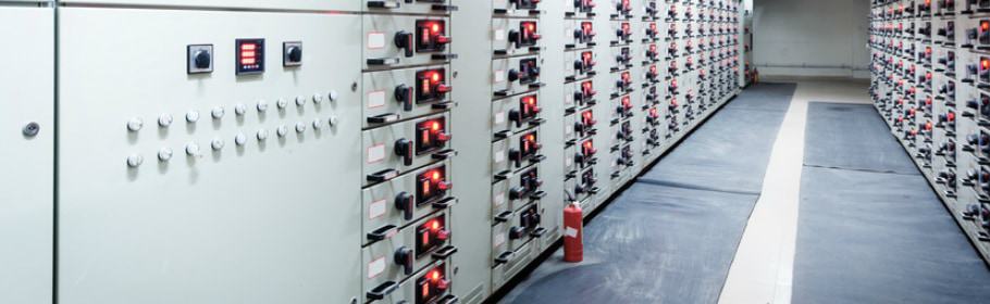
Insulating matting is a essential component of electrical safety and is specified and installed to provide protection against electrical shock and hazards around electrical equipment, such as switchboards and switchgear – this can include Low Voltage, Medium Voltage & High Voltage.
As part of a facilities standard risk assessment, where a potential for electrocution is present, then electrical insulating safety matting (commonly referred to as switchboard or switchgear matting) is recommended in the HSE’s Safe Working Practices for Electricity At Work document (HSG85) where it references BS EN 61111: 2009 (Live Working: Electrical Insulating Matting British Standards Institution).
“providing and using correct personal protective equipment (PPE) to reduce the risk of contact with live parts or earth, eg insulating gloves, insulating matting (see BS EN 61111:200917). If there is a risk of burns from arcing or flashover that cannot be avoided, consider the use of adequately rated, thermally insulating, flame-resistant, arc flash clothing or PPE (including face/eye protection).” HSG85
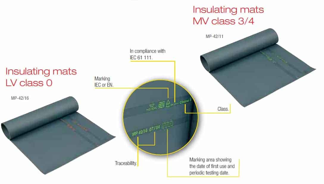
The range of CATU insulating matting conforms to the standards set out in IEC 61111 and provides MV-HV electrical protection for personnel working on medium and high voltage switchgear, switchboards, control panels and transformers.
The IEC 61111 standard sets out the requirements that must be met and supersedes the standard CLC/TS 61111:2006 and includes the following significant technical points:
General review of the requirements and test provisions
Modification of the test procedure for slip resistance matting
Specification of standard and alternative types of electrodes for the proof test
The conditioning time for low temperature folding test of insulating matting
IEC 61111:2009 is applicable to electrical insulating matting made of elastomer for use as a floor covering for the electrical protection of workers on electrical installations, including 11kV and 33kV substations.
LV MV HV Insulting Matting Explained
Selection of insulating mats for specific applications depends on the worker exposure to operating voltage and matting is tested to withstand certain specified voltages – referred to as the safe working voltage detailed below. Electrical safety matting is tested to a higher voltage than the certified use voltage – the voltage at which the matting is certified to is the Safe Working Voltage.
CATU Electrical insulating matting is specified and tested to IEC 61111 Category C with working temperatures to – 40°C for the following voltages:
Products that are covered by the IEC 61111 standard include live working, electrical insulating materials, insulating matting, elastomers, floor coverings, electrical safety, electric shocks, safety devices, occupational safety, classification systems, grades (quality), marking and testing.
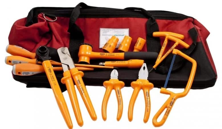
See live working tools for further information about insulated tools in accordance with IEC Standards for working on energised low voltage cables.
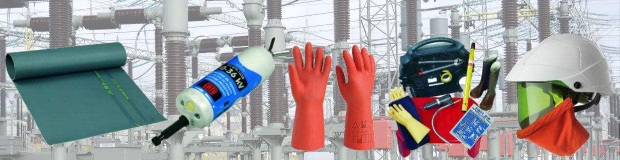
Protecting Jointers & Electrical Engineers When Working Live On Cables & Switchgear – comprehensive ranges of insulating matting and insulated tools.
Catu Electrical insulating matting
Electrical insulating matting is available in roll form for placement and rolling-out in front of medium/high voltage switchgear rooms, motor control centres (MCC), traction power substations and UPS rooms.
Portable pre-cut insulating mats are available to provide protection to site engineers and cable jointers working on electrical installations in plant and lift control gear rooms – often used to provide electrical protection when 11kV/33kV jointing, terminating and glanding cables into electrical distribution equipment.
Complete range of LV-HV Insulating Matting for all medium and high voltage switchgear, switchboard and substation electrical safety protection up to 33kV.
Recommendations For Use & Storage of Matting
It is vital to store and use electrical insulating mats in the correct manner in order to prolong their lifespan and ensure they continue to function and provide the insulation levels required. When storing or transporting the matting it should be properly stored and should not be bent or deformed.
The insulated mats should also not be stored or used close to any excessive heat sources or exposed to direct sunlight for long periods. The ideal storage temperature for the mats is between 10°C and 21°C.
When using and installing any insulating matting, a visual inspection should be carried out first. If the mats are dirty they should be cleaned with soap and water and then dried, respecting the operation temperatures mentioned previously.
Ideal operating temperatures are between -40°C and 55°C and the mats should not come into contact with any chemical products as this can also damage the rubber. When installing the mats, place them on a clean smooth floor devoid of any aggressive elements.
Once installed, periodic inspection of the insulating matting should be carried out and mats should not be used if they have not been electrically tested for 12 months.
Typically, Class 1, 2, 3 and 4 matting should be tested every 12 months in accordance with IEC61111 – often a visual inspection for low voltage Class 0 insulating matting is adequate depending on matting condition. Aged matting showing clear deterioration should be subject to routine dielectric test to check and ensure insulating levels are maintained.
Insulating Matting FAQ’s
How Do Insulating Mats Work?
Rubber is a natural dielectric material and therefore inhibits the flow of electric charge as a result of its molecular structure preventing the free flow of electrons.
Where Should I Use Insulating Matting?
Insulating matting should be installed in front of low, medium and high voltage switchboards, in front of machine control gear, in plant and lift gear control rooms and as portable protection for site engineers working on live electrical equipment.
The working voltage and size of matting is dependent upon the class of the mat. CATU insulating matting is supplied in 5m or 10m long rolls and as either 0.6m wide, 1m wide or 1.2m wide dependent on class. The thickness of the matting is also dependent on voltage class.
What Is The Double Triangle?
Matting with the “double-triangle” symbol confirms the insulating matting is suitable for live working according to IEC 60417-5216.
♦ Further Reading
For more reading about Electrical Safety, read the T&D blog:
T&D distribute the most extensive range of LV, MV & HV Cable Jointing, Terminating, Cable Pulling & Installation Equipment – we service UK and international clients working on underground cables, overhead lines, substations and electrical construction at LV, 11kV, 33kV and EHV transmission and distribution voltages.
Thorne & Derrick invite you to join LinkedIn’s largest LV-HV Electrical Discussion Group : Low & High Voltage Power, Cabling, Jointing & Electricals. Discussion subjects include cable installations, cable jointing, substation, overhead line and electrical construction at LV, 11kV, 33kV and EHV. Network, engage and promote your profile, company or products with over 10,000 influencers.
Sealing Cable Ducts
Guest Blog: Steve Groocock (Duct Seal Products – Account Manager at Filoform UK)
Product Category: Cable Duct Sealing
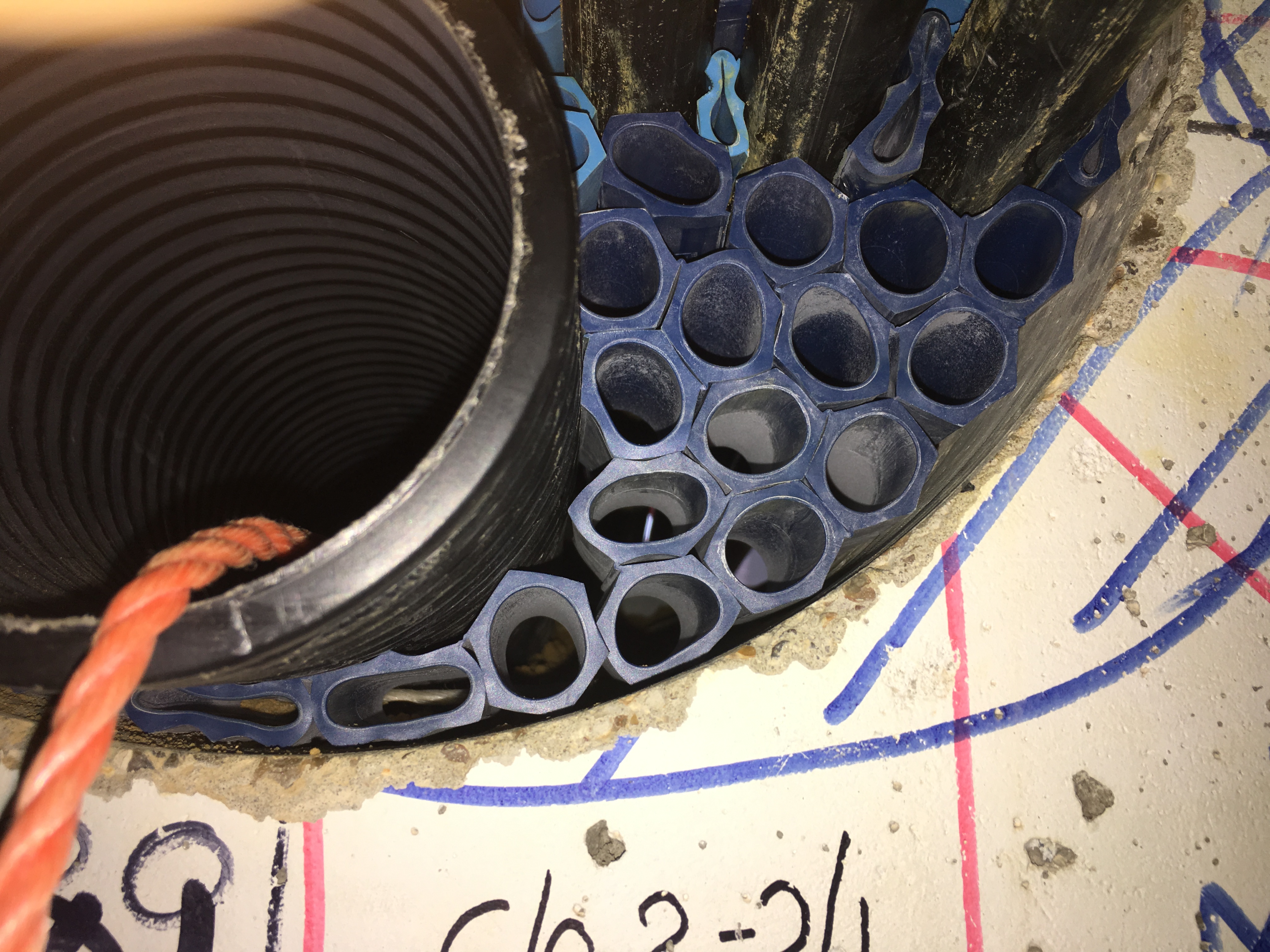
Filoform FiloSeal +HD is a duct sealing system specified to protect and seal larger heavy armoured power and high voltage cables in LV, MV & HV substation ducts, bore holes or transit frames – the duct seal provides a strong support and cable sealing system using hexagonal tubes building a re-enterable honeycomb structure to resist water, gas and fire.
Re-enterable cable duct seals are easy to apply regardless of the type of cable scenario in the cable ducts as it uses a strong but flexible hexagonal tube structure to support the cable and provide a strong backing for the cable seal.
The duct seal system provides waterproof and gastight sealing of LV-HV and 11kV-33kV power cables into ducts. The FiloSeal+HD is suitable for any cable configuration (single, trefoil cables or multiple cables) contained within one duct and also allows for easy re-entry of the duct seal to add or remove cables or pipes as required.
Filoform Filoseal+HD is covered by a Test Report documenting successful pass status at Nedlab Laboratory for the following – this is based upon using Filoform’s hexagonal support system and sealing cable using their MD+ sealant.
Pressure Test, Bending Test & Pull Strength
Resistance Test Against Chlorine, Methane Gas & Chemicals In Hazardous Areas
Steve Groocock is the Duct Seal Product Manager at Filoform. Below he explains about attending a data centre site where he provided installer training prior to the installation of Filoseal +HD Re-enterable Duct Seal System.
“A skill is something that is learned over a period of time but sometimes it is best to pass along experience to a new user of any equipment, this includes cable duct seals. Recently, I attended site for a company who were working on the LV cabling associated with a new build data centre into an existing building structure.
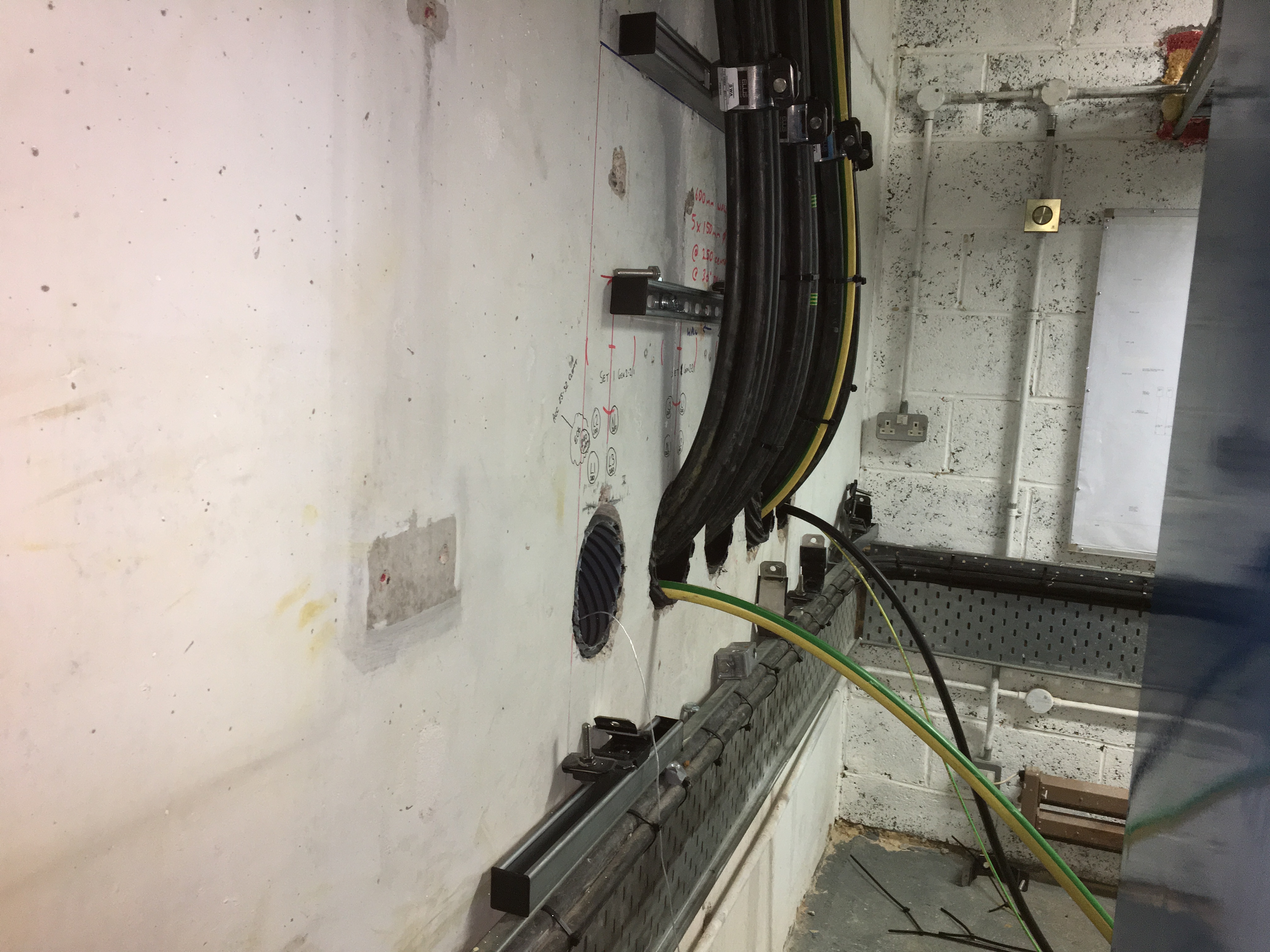
The LV cable, ducting and electrical distribution system utilised existing switch rooms where possible but in order to add capacity to these areas, new penetration holes for the cabling needed to be added. These holes were core drilled directly through the existing structure. Once the cables had been pulled, there remained clear passages for the ingress of moisture, gas, dust and rodents into cable ducts.
Taking the strips of adjoined hex tubes, insert them around and between the cables to be sealed ensuring the spacing required is maintained – the strips can be inserted as a flat line or rolled to form a tight group of 5. If space is not available, the strip of hex tubes may be torn down to individual hex tubes.
Start at the bottom of the cable duct with the large blue tubes and build up to completion. Should there be heavy cables in the ducts, such as 11kV/33kV high voltage power cables, the hex tubes can be nested i.e. one small tube placed inside the other larger tube. The small light blue hex tubes are used to fill and seal the remaining small gaps in the cable duct. The installer should ensure the tubes are packed tightly to prevent cable movement.
Filoseal+HD duct sealing kits have been tested to provide watertight, gastight and/or fire resistant cable seals and were thus specified to fill in the voids in the concrete core drilled holes at the data centre.
Training took two hours and in this time it was up to me to pass on as much experience as possible at a steady pace so the new installer could take it understand and adopt the knowledge. The installer had previously not seen a duct sealing system like this so I took time to familiarise them with the component parts and how a finished cable duct seal installation should look like by way of a sample in a clear duct replica. I also showed the excellent Filoform HD installation video which can be viewed below.
Once we had seen the video and experienced the component parts of the duct seal we started to seal one side of one cable duct. The customer will be sealing both sides of the cable duct wall – we can see this in the pictures upon insistence from their end client.
The hands on training starts with myself and the trainee cleaning and abrading the cables and cable duct for the first 20-25mm inside the hole in the wall – cleaning cloth is provided with the duct seal kit. Preparation is key to the whole system – the most important point I stressed to achieve a hexagonal backing piece between each and every cable to create a reliable water and gastight cable duct seal.
The hexagonal tubes are placed around the cables to be sealed filling up all the gaps using the large and small hexagonal backers to ensure the cable support system is compact and tight resembling a honeycomb structure.
This is explained in the Video and instructions supplied with the duct seal kit but until seen it is not necessarily clear as to why. The space is there to ensure the duct sealant component, called Filoseal MD+, can reach all the areas of the void or cable duct needed to be sealed. This site was particularly challenging as the low voltage cables were held down close and clamped to the work face by cable cleats. However, I moved to the other side of the wall and moved the cables in a pit until my trainee could get the hexagonal pieces between each and every cable and between the cables and the core drilled hole edge.
Here the cables are pictured clamped to the cable channel using trefoil cable cleats as the cables depart the duct which was sealed using Fioloseal type duct sealing mastics.
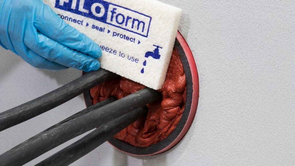
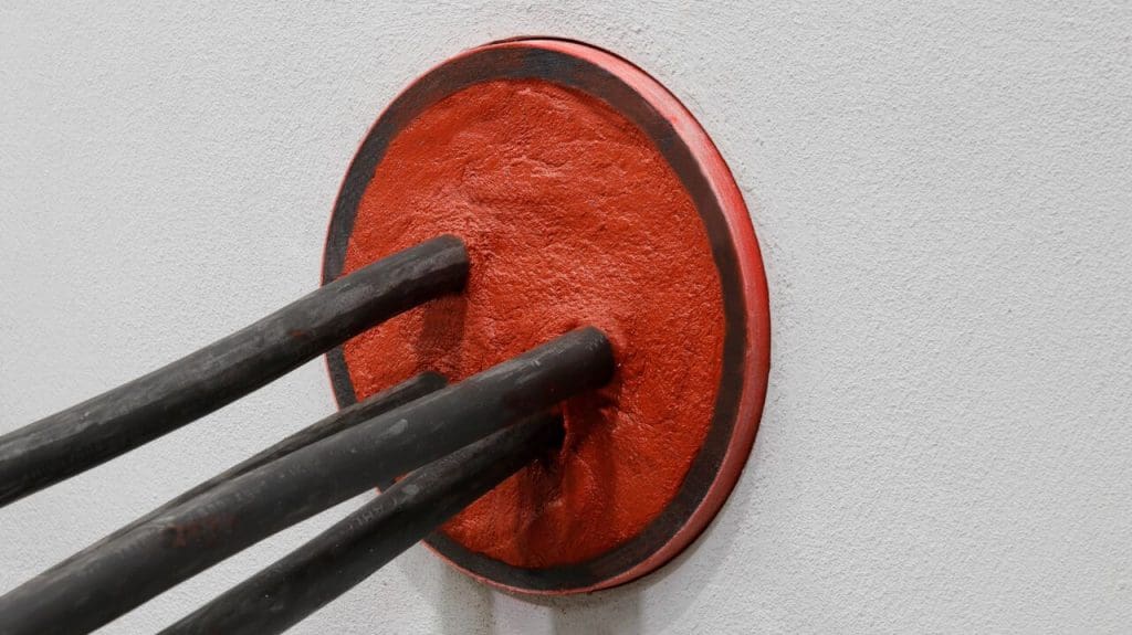
This is the end of stage one. Once we both looked and examined the backing ensuring there were gaps around the cables to be sealed as specified, we moved on to the addition of the sealing mastic. The cable sealing mastic can be applied using a standard mastic gun, however we recommend investment in a quality installation gun. Once the sealant mastic is loaded in the gun I demonstrated on the lower half of this cable install how to ensure a cable seal by running a good bead around the hole edge on every cable. Once we had gone through several tubes of mastic we brought out the finishing sponge to wipe down and tidy the mastic finish – the duct sealant can take from 4 to 20 days to fully cure depending on local ambient temperatures and air humidity levels. Typically in the UK curing takes 8-20 days and backfilling of the installation should be avoided until at least 10 days after installation.
When backfilling ensure adequate packing is below the sealed cables in the duct before adding materials above the cables. In a vertical cable duct, group together strips or rolled groups of tubes and squeeze them into the a duct as one single unit.
Then proceed to maintain the required cable spacing by adding either large or small tubes (groups of or singly).
Duct Sealing – Preparation Is Key
The mastic should be patted in and around every cable ensuring each and every part of the cable duct seal was treated the same way – this patting motion encourages the cable sealant mastic to adhere to the hexagonal backing. Final checks led me to further pat parts between cables using the sponge edge.”
Duct seals suitable for LV-HV power cables in single, trefoil or multiple configurations, including 11kV Triplex and 33kV high voltages
Provides advanced and assured sealing against water and gas for cable ducts, bore holes and openings
Re-enterable sealing system future-proofed for retrofit of new cables or re-routing of existing through cable ducting
Cable duct seals provide protection of substations and basements against flood, fire and gas ingress dangers
Conclusion
Filoseal+HD duct seal system using MD+ has been heavily tested against pressure, pulling forces, chemicals, gases and hydrocarbons for use with low, medium and high voltage cables. Below we can summarise the results from Nedlab Laboratory Test Reports.
Duct Seal Test Description
Measurement
Result
Pass or Fail
Pressure
2.0 Bar
1.0 Bar long term, 2 Bar short term
PASSED
Pulling Force
100Kg
100Kg – 1000 Newtons
PASSED
Bend Test
10xd at 45 Degrees
10xd at 45 Degrees, with 1 Bar pressure
PASSED
Chlorine Gas
100% for 7 Days
Slight change on colour and texture
PASSED
Methane Gas
100% for 7 Days
Slight change on colour and texture
PASSED
Diesel
100% for 2 Years
Hardly any change
PASSED
Petrol / Benzene
100% for 2 Years
Hardly any change
PASSED
Ethanol
100% for 42 Days
Hardly any change
PASSED
AD Blue
100% for 21 Days
No change
PASSED
ASTM Oil
100% for 2 Years
Hardly any change
PASSED
Hydrogen Sulphide (H2S)
200ppm for 5 Days
Hardly any change
PASSED
Final Pressure Test – after completion of the bending and pull strength test the cable duct seals are tested at a pressure of 2.0 Bars.
Note the Test Results documented above have been done in accordance with Filoform installation instructions, however values achieved in field installations can vary if the instructions are not followed and results may vary depending on cable and duct tolerances such as cable duct size, material and cable density volume.
THORNE & DERRICK are national distributors LV, MV & HV Cable Installation, Jointing, Substation & Electrical Equipment – we service UK and global businesses involved in cable installations, duct sealing, cable jointing, substation, overhead line and electrical construction at LV, 11kV, 33kV and EHV.
Since 1985, T&D have established an international reputation based on SERVICE | INTEGRITY | TRUST.
Contact us for 3M Electrical, ABB, Alroc, AN Wallis, CATU Electrical, Cembre, Centriforce, CMP, CSD, Elastimold, Ellis Patents, Emtelle, Euromold, Filoform , Furse, Lucy Electric & Zodion, Nexans, Pfisterer, Polypipe, Prysmian, Roxtec, Sicame, WT Henley.Invitation: Thorne & Derrick invite you to join LinkedIn’s largest LV-HV Electrical Discussion Group : Low & High Voltage Power, Cabling, Jointing & Electricals. Discussion subjects include cable installations, cable jointing, substation, overhead line and electrical construction at LV, 11kV, 33kV and EHV. Network, engage and promote your profile, company or products with over 10,000 influencers.
Celebrating Charlie & Ella’s Level 4 Sales Executive Apprenticeships At Thorne & Derrick International, we are proud to champion talent development and recognise the dedication required to achieve professional growth. We are therefore delighted to congratulate Charlie Baines and...
Thorne & Derrick will be Exhibiting at Solar & Storage Live UK 2026 at the NEC Birmingham from 22nd–24th September, showcasing our support for HV Cable Accessories, Joints, Terminations, Separable Connectors, Cable Tooling and Grid Connection Products used across...
































 working on medium and high voltage switchgear, switchboards, control panels and transformers.