EV Charging Feeder Pillars
EV Feeder Pillars
EV Charging
Lucy Zodion manufacture a wide range of products suitable to provide Low Voltage Electrical Power Distribution for EV charge points – from distribution network operator (DNO) accredited cut-outs and isolators for on-street chargers, to feeder pillars for electrical vehicle charging.
Meet the increasing demand for accessible EV charging points with power distribution solutions that connect DNO supply with charging outlets. Lucy Zodion’s adaptive and reliable supply solutions consider the charge speeds and times each EV charge point is capable of, from fast to super, to ensure you receive the most suitable and compatible option.
As one of the UK’s leading suppliers of pre-wired power distribution enclosures, Lucy Zodion have developed a standard range of pillars that will support EV charge point requirements that fall into the four categories of main current rating: 100 Amp, 200 Amp, 400 Amp and 630 Amp, providing a link between the DNO and EV charge points. The configuration of all EV feeder pillars in this range can be upgraded once installed to meet future demand requirements.
3-Phase AC Supply | 100 Amp Feeder Pillars
| EV Feeder Pillar Type |
Fortress Pillar Size 14 |
| Part Number |
EV1008007 |
EV1003022 |
EV1002043 |
EV1001050 |
| Rating |
7kW (40A SPN) |
22kW (40A TPN) |
43kW (63A TPN) |
50kW (80A TPN) |
| No. of charge points per feeder pillar |
8 |
3 |
2 |
1 |
| Dimensions H, W, D (mm) |
1300,1250,450 |
1300,1250,450 |
1300,1250,450 |
1300,1250,450 |
| Weight |
250kg |
250kg |
250kg |
250kg |
| Main incomer (MCCB) |
✓ |
✓ |
✓ |
✓ |
| Mild steel: Hop dip galv 3mm |
Wedgelocks |
Wedgelocks |
Wedgelocks |
Wedgelocks |
| Lock type |
✓ |
✓ |
✓ |
✓ |
| Anti-condensation heater |
✓ |
✓ |
✓ |
✓ |
100 Amp supply pillar is the smallest feeder pillar within the range and is available in four different configurations. These pillars cover 7kW supplies through to 50kW, with a differing number of connections on each solution.

100 Amp Supply Feeder Pillar
3-Phase AC Supply | 200 Amp Feeder Pillars
| EV Feeder Pillar Type |
Fortress Pillar Size 24 |
| Part Number |
EV1008007 |
EV1003022 |
EV1002043 |
EV1001050 |
| Rating |
7kW (40A SPN) |
22kW (40A TPN) |
43kW (63A TPN) |
50kW (80A TPN) |
| No. of charge points per feeder pillar |
16 |
6 |
4* |
3* |
| Dimensions H, W, D (mm) |
1600,1250,450 |
1600,1250,450 |
1600,1250,450 |
1600,1250,450 |
| Weight |
275kg |
275kg |
275kg |
275kg |
| Main incomer (MCCB) |
✓ |
✓ |
✓ |
✓ |
| Mild steel: Hop dip galv 3mm |
Wedgelocks |
Wedgelocks |
Wedgelocks |
Wedgelocks |
| Lock type |
✓ |
✓ |
✓ |
✓ |
| Anti-condensation heater |
✓ |
✓ |
✓ |
✓ |
* Use of load management on chargers required

200 Amp Supply Feeder Pillar
200 Amp supply pillar within our range is available in four different configurations.
These pillars cover 7kW supplies through to 50kW, with a differing number of connections on each solution.
3-Phase AC Supply | 400 Amp Feeder Pillars
| EV Feeder Pillar Type |
Fortress Pillar Size 40 |
| Part Number |
EV4001222 |
EV4008043 |
EV4005050 |
EV4002120 |
| Rating |
22kW (40A TPN) |
43kW (63A TPN) |
50kW (80A TPN) |
120kW (250A TPN) |
| No. of charge points per feeder pillar |
12 |
8* |
5* |
2* |
| Dimensions H, W, D (mm) |
2200/2850/600 |
2200/2850/600 |
2200/2850/600 |
2200/2850/600 |
| Weight |
400kg |
400kg |
400kg |
400kg |
| Main incomer (MCCB) |
✓ |
✓ |
✓ |
✓ |
| Mild steel: Hop dip galv 3mm |
Barlock (3 point) |
Barlock (3 point) |
Barlock (3 point) |
Barlock (3 point) |
| Lock type |
✓ |
✓ |
✓ |
✓ |
| Anti-condensation heater |
✓ |
✓ |
✓ |
✓ |
400 Amp supply pillar within our range is available in four different configurations.
These pillars cover 22kW supplies through to 120kW, with a differing number of connections on each solution.
3-Phase AC Supply | 600 Amp Feeder Pillars
| EV Feeder Pillar Type |
Fortress Pillar Size 40 |
| Part Number |
EV6301822 |
EV6301043 |
EV6307050 |
EV6303120 |
| Rating |
22kW (40A TPN) |
43kW (63A TPN) |
50kW (80A TPN) |
120kW (250A TPN) |
| No. of charge points per feeder pillar |
18 |
10 |
7 |
3 |
| Dimensions H, W, D (mm) |
2200/2850/600 |
2200/2850/600 |
2200/2850/600 |
2200/2850/600 |
| Weight |
400kg |
400kg |
400kg |
400kg |
| Main incomer (MCCB) |
✓ |
✓ |
✓ |
✓ |
| Mild steel: Hop dip galv 3mm |
Barlock (3 point) |
Barlock (3 point) |
Barlock (3 point) |
Barlock (3 point) |
| Lock type |
✓ |
✓ |
✓ |
✓ |
| Anti-condensation heater |
✓ |
✓ |
✓ |
✓ |
Further Reading
➡ More Lucy Zodion Blogs:

Galvanised & Stainless Steel | GRP | Pre-Wired | Underground Retractable Feeder Pilars
THORNE & DERRICK SPECIALIST ELECTRICAL DISTRIBUTOR
LV ♦ MV ♦ HV
T&D distribute the most extensive range of LV, MV & HV Cable Jointing, Terminating, Pulling & Installation Equipment – we service UK and international clients working on underground cables, overhead lines, substations and electrical construction at LV, 11kV, 33kV and EHV transmission and distribution voltages.
- Key Products: MV-HV Cable Joints & Terminations, Cable Cleats, Duct Seals, Cable Transits, Underground Cable Protection, Cable Jointing Tools, Feeder Pillars, Cable Ducting, Earthing & Lightning Protection, Electrical Safety, Cable Glands, Arc Flash Clothing & Fusegear.
- Distributors for: 3M, ABB, Alroc, Band-It, Catu, Cembre, Centriforce, CMP, Elastimold, Ellis Patents, Emtelle, Furse, Lucy Zodion, Nexans Euromold, Pfisterer, Polypipe, Prysmian, Roxtec.
")
LV – Low Voltage Cable Joints, Glands, Cleats, Lugs & Accessories (1000 Volts)
")
MV HV – Medium & High Voltage Cable Joints, Terminations & Connectors (11kV 33kV EHV)

Cable Laying – Underground Cable Covers, Ducting, Seals & Cable Pulling Equipment
Prevent Moisture in Electrical Systems
3M Scotchlok 314
The electrical systems used in stadiums are often exposed to harsh weather conditions such as heavy rain and moisture, creating serious consequences if they fail, with events potentially cancelled or delayed. Problems can occur in hard to reach areas such as floodlights or roof lights, making repair and maintenance difficult and expensive.
Moisture can get into places such as the junction boxes that connect to lighting and other electrical systems, creating poor and unsafe connections. These problems can be solved using 3M Scotchlok 314 Insulation Displacement Connectors (IDC’s), which prevent moisture from getting into electrical installations and causing damage.
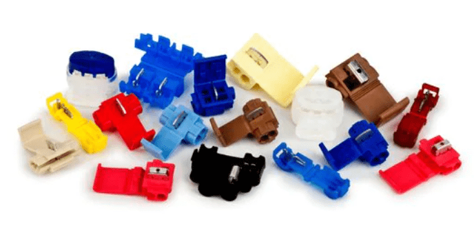
3M Scotchlok Insulation Displacement Connectors
Proven Cable Splicing Technology Designed for your Specific Applications
Scotchlok 314 is an insulation displacement connector used for assembling electrical installations. The wires are inserted into the Scotchlok connector, and when the installation is complete, the connection is secured. This makes it easy and simple to work with, especially in difficult situations.
Due to the connector’s moisture-repellent properties, it’s extremely good for outdoor electrical installations such as exterior lights, signs, sprinkler systems, landscape lighting and other moisture resistant applications at low voltage.
- A “live-spring” joint is made by driving the “U” contact down into the connector
- As the “U” contact is pressed into the connector, it grasps the conductors as it displaces insulation
- The contact grips the conductor(s) and holds with firm, resilient pressure
Scotchlok IDCs incorporate a full wire range capability, an increased port size that accommodates up to 4.82mm insulation sizes, double “U” elements and a solvent-resistant plastic construction.
There are 15 different 3M Scotchlok IDCs to choose from to meet a variety of uses, including fixture, appliance, automotive, marine and control circuit wiring.
3M Scotchlok IDCs have a range of approvals and ratings that meet with industrial standards. To learn more give us a call.

THORNE & DERRICK are national distributors of LV, MV & HV Cable Installation, Jointing, Duct Sealing, Substation & Electrical Equipment – we service UK and global businesses involved in cable installations, cable jointing, substation earthing, overhead line and electrical construction at LV, 11kV, 33kV and EHV.
Since 1985, T&D have established an international reputation based on SERVICE | INTEGRITY | TRUST.
Contact us for 3M Electrical, ABB, Alroc, AN Wallis, CATU Electrical, Cembre, CMP, CSD, Elastimold, Ellis Patents, Emtelle, Euromold, Filoform , Furse, Lucy Electric & Zodion, Nexans, Pfisterer, Polypipe, Prysmian, Roxtec, Sicame, WT Henley.

Cable Management & Cable Protection
Usage of safe electric cables and electrical safety outdoors is as significant as it is indoors. Cables are protected so that they are able to sustain in detrimental conditions and outdoor environment. Protection is primarily needed from external influences like mechanical damage, temperature, water and other such factors. Nonetheless, the electric cables should be protected in such a way that it allows continued passage of electricity.
Assurance of a safe working environment requires strong and durable protection against any electrical hazards, and to achieve it cables must be able to handle voltage safely and insulation must be tough enough for the environment. Furthermore, the connections must be reliable and cable covers can be used to provide protection against external environmental factors.

Cable Management | How To Protect Outdoor Electrical Cables
In working environments, the cables run across the path of vehicles and pedestrians increasing the risk factor. To prevent accidents, cable and hose protectors can be used which are suitable for all type of industries including construction sites and traffic signals.
In large work areas where heavy machinery and tools are used, loose cables can create a trip hazard and cause fatalities or injuries. Moreover, loose wires may lay across in the way of machines, making itself more prone to damage and accident. Highlighting the trailing cables with anti-slip marking tape and floor stands will minimize trip hazards on worksite, and loose wires can be protected using cable protectors which offer defence against damage from vehicles and pedestrians. Heavy duty cable protectors and cable ramps are ideal for high walking-traffic in high traffic areas like warehouses, construction sites, markets, etc. These durable cable covers allows traffic to pass over without imposing any considerable damage to cables.

Cable Management | How To Protect Outdoor Electrical Cables
Cable ramps are easy to use and possess a convenient button-down lid to insert and remove the cables easily. Hence, these industrial cable covers and cable ramps are used extensively in commercial and industrial settings, as they minimize trip hazards and protect electrical cables.
Cable management is an imperative component to ensure the protection of electrical cables because it helps to maintain basic functionality and promotes safe working conditions.
Cable management systems like cable trays and reels form a rigid structure to support and protect the electrical cables against insulation damage, cable damage, crosstalk and overheating.
Cable protection high quality systems like conduit system and trunking system can be used for complex configurations, making it capable to securely carry different types of cables at a time. In order to reduce the safety risk, the electrical cables can be protected using heavy duty cable ties and nylon cable ties (or cable cleats) which is an effective way to organize and manage the electrical cables. Conclusively, it is highly significant to protect the electrical cables effectively, otherwise these cables can cause harm and pose a serious safety risk.

Cable Management | Cable Cleats, Cable Clamps, Cable Hangers, Cable Ties

Stokbord Drum Cable Protection for Underground Utility Cables
CABLE SAFETY HOOKS & EQUIPMENT
OSHA maintains general industry regulations on walking and working surfaces that guard workers against hazards and the risk of injury including clutter, protruding objects and wet conditions. These Health & Safety hazards can harm everyone in a facility, regardless of title or job responsibilities.
Slips, trips, and falls cause nearly 700 fatalities per year and many more injurious accident in the workplace according to the Bureau of Labor Statistics. The CableSafe range of products ensure all cables, wires and hoses are suspended off the ground especially in high traffic work areas such as production floors, machinery spaces and deck level areas where maintenance is being carried out.
CableSafe Safety solutions are critical cable essentials and are well proved construction safety products.

Cable Safety Equipment | Cable Stand | Cable Bridge | Cable Rail | Cable Guard | Dropped Object Prevention Mats
FURTHER READING

THORNE & DERRICK are national distributors of LV, MV & HV Cable Installation, Jointing, Duct Sealing, Substation & Electrical Equipment – we service UK and global businesses involved in cable installations, cable jointing, substation earthing, overhead line and electrical construction at LV, 11kV, 33kV and EHV.
Since 1985, T&D have established an international reputation based on SERVICE | INTEGRITY | TRUST.
Contact us for 3M Electrical, ABB, Alroc, AN Wallis, CATU Electrical, Cembre, Centriforce, CMP, CSD, Cubis Elastimold, Ellis Patents, Emtelle, Euromold, Filoform , Furse, Lucy Electric & Zodion, Nexans, Pfisterer, Polypipe, Prysmian, Roxtec, Sicame, WT Henley.

Electrical Safety Products
Which personal protective equipment or electrical safety products are used for head protection? There are three different types of head protection that are commonly used:

- Industrial Safety Helmets (Hard Hats) – designed to provide protection against falling materials from a height or swinging objects.
- Industrial Scalp Protectors (Bump Caps) – designed to provide protection from hitting against static objects.
- Caps/Hair Nets – designed to protect against entanglement.
Tasks in which head protection might be needed include:
- Construction
- Building Repairs
- Working in Excavations or Tunnels
What are 3 types of personal protective equipment?
Personal protective equipment (PPE) is industrial safety products used by workers, contractors or visitors to protect their bodies from workplace hazards. PPE can be classified in the following categories, based on the type of protection offered by the equipment:
- Eye protection– for example, safety spectacles/goggles, eye shields, Face shields etc.
- Respiratory protection– for example, disposable, cartridge, half or full face masks.
- Working from heights– for example, harness and fall arrest systems.

Eye Protection
What are 5 types of PPE?
The 5 different types of PPE are:
- Face Shields
- Gloves
- Gowns
- Head Covers
- Masks
What are the safety equipments?
PPE is the safety equipment that provides protection to users against health or safety risks at work. This include industrial safety products such as safety helmets, gloves, eye protection, high-visibility clothing, safety footwear and safety harnesses.

Electrical Safety Footwear – Jointers & Linesmens Boots
➡ See also Electrical Safety Equipment and Arc Flash Clothing.
What are the types of safety?
OSHA listed five different types of hazards that affect most of the workplaces. These hazards can be found in every kind of industry and should be handled appropriately to keep workers from injury or health issues.
- Safety Hazards: Such hazards are dangerous conditions in a facility that can cause injuries, illness, or even fatality like spills, working from height, unguarded machinery, wiring issues, confined spaces, forklifts, and much more.
- Biological Hazards: These hazards are typical for those who work with animals, people, or infectious plant materials. People working in daycare centres, hospitals, and nursing homes can be exposed to blood-borne pathogens.
- Physical Hazards: Physical hazards include environmental factors that can cause harm to workers even without direct contact. Radiation, sunlight exposure, working in extreme temperatures, and noisy environment are few examples of physical hazards.
- Ergonomic Hazards: Such hazards can be the most difficult to identify, but can easily cause strain and injury to the body. Employees can face ergonomic hazards if their workstations or chairs are not adjusted properly, if they are making repetitive movements in awkward position and other situations where the body and muscles are overstressed.
- Chemical Hazards: Any chemicals in the workplace could put individuals at risk. Some chemicals are even more harmful than others, but even common chemicals can cause skin irritation, serious illness, or breathing problems.
Further Reading
Arc Flash Learning & Resources

Thorne and Derrick are proud to be distributors of ProGARM arc flash coveralls and protection.
We can help – should you require arc flash calculators or advice on the type of clothing and protection available please do not hesitate to contact us.


Cable Drum Handling
Transport, Storage & Installation Recommendations for Halogen-free Shipboard Cables from Helkama
The purpose of this guide about Cable Drum Handling is to illustrate how cable damages can be avoided by correct handling and storage practices.

Handling Cable Drums
Drum flanges are marked to provide vital information to assist with the handling of the drums and the installation of the cable. This information includes drum weight, a mark on the flange indicating the end of the cable, and an arrow indicating the rotating direction of the drum for rolling or transportation. If the handling is done correctly, the drum will protect the cable from damages. The forks of the forklift must be longer than the width of the drum, so that the lagging is not damaged. Raise the forks of the forklift sufficiently (15-20 cm) above the ground.
Insufficient cable drum lifting height may cause the drum to be dragged on the ground and eventually get damaged or dropped off the forks, especially if the ground surface is uneven. The drums may be placed and stacked on pallets to make it safer and easier to move them. Don’t push the drum with the forklift.
Storage of Cable Drums
Cable drums shall be stored properly. Improper storage conditions can easily cause damage to cable drums or the actual cables. Cable ends shall be sealed with caps to prevent ingress of water. The caps must be protected to avoid any mechanical risk and exterior shocks. Always check drums before moving. Drums shall be stored on a level and firm surface (e.g. timber baulks, flange edges) standing upright and strapped/wedged securely to place. Do not store the drum with the flange flat on the ground.
Drums shall not be standing in water or be stored in continually damp conditions.
Failure to provide these conditions is likely to result in timber rot and weakening of the flange with potential breaking or collapse of the drum to the point where the cable will end up resting on the ground. Any of these outcomes will make later installation of the cable more problematic or impossible.
Cables with coloured outer sheaths shall not be stored in direct sunlight to prevent fading.
Cables shall be protected against direct sunlight with suitable protective packaging, such as plastic sheeting. If the cable is used progressively (partial lengths are cut and used), the exposed cable end must be immediately sealed with a new end cap. Heat shrinkable end caps are recommended.
Packing of Cables
Before shipping the cable drums shall be packed correctly for transportation. The packing consists of the following items:
- Plastic foil is wrapped over the cable layers and affixed with adhesive tape.
- The cladding boards are attached with a plastic or steel strap (optional). Do not tighten the strap too much to avoid damage to the cable.
If the cladding boards need to be attached to the flanges of the drum with nails, the nailing shall be done making sure the nails hit the middle of the flanges, and don’t damage the outer cable layers.
Transport of Cable Drums
The bigger cable drums shall be loaded in the container or transportation vehicle in vertical position, i.e. standing up, so that they don’t move during transportation. For cable drums with diameter ≤ 1,2 m a horizontal position can also be used and the drums can be stacked.
Secure the drums firmly.
The round shaped cable drum rolls easily. Make sure that each drum is secured in place with stoppers/wedges to prevent rolling during transportation and storage.

During transportation, the drum shall be fastened with a combination of wedges and transportation straps to tie down the front and rear of the drum, to prevent movement of drums.
Lifting cable drums with a forklift is only allowed from the “flange side”. To avoid damage, never touch the cable or its protective cover with the fork.
Main dangers are the invisible damages that lead to unusable cables. Therefore some basic guidelines need to be followed. The cable itself must always be protected. Cable or drum, damaged by handling etc., must be checked before use.
The unloading and handling shall be done carefully using correct lifting equipment. When handling the drum with a forklift truck, place the drum vertically on the forks. Never let a drum fall during unloading.
Inspect the cables when they arrive on site. Check the condition of the end caps of the cables and the lagging (a break in the wooden lag could tear the outer sheath of the cable).
If the cable drums show signs of damage from handling and/or storage, any warranty obligation given for the cable drums and any subsequent problems resulting from it, are null and void.
INSPECTION
Drums, cables and delivery documents must be inspected when the products are first received at the storage area. The packing list and the product order have to match the received products. In case of document flaws it is necessary to contact the nearest Helkama representative to assess the situation and advise an appropriate solution.
The received drums should be carefully inspected to ensure that no damage occurred during transportation. If any damage is discovered on the drum, it is advisable to also check the cable for damages. It is essential to inform Helkama representative if any cable damage or severe drum damage is found. The damage shall be documented before moving the drum in order to demonstrate the situation properly.
LONG-TERM CABLE STORAGE
Always inspect the drum before moving it from long-term storage.
Transport vibrations and movement, weathering or environmental damage can cause changes in the drum and an assessment of the state of the drum is necessary. In changing dry and wet weather, or consistently dry and hot weather, the wooden sections of the drum can shrink and the whole drum could become unstable and cause damage to the cable when moving the drum. Therefore, the transverse bolts must be tightened with a torque wrench before the drums are moved, to prevent the drums from collapsing. To ensure the bolts stay tight they must also be re-tightened during cable installation.
Note that timbers of the drum flanges and barrels that have shrunk are also likely to have loose nails, but they are harder to fix than bolts. Apply caution and vigilance during the cable unwinding to identify loose nails and reduce possible damage to the cable.

If the cable ends are accessible, it is recommendable to inspect the condition of the end caps. The end cap is designed to prevent the ingress of water. If the cap or seal has been absent for a long time (more than one month); or the cable end faces up toward the sky; or the end cap has been absent during periods of rain; or any form of cable end deterioration / ageing / swelling / or soiling is observed; it is recommended that the cable end be cut back 300 mm and re-examined for presence of moisture. If moisture is found, cut back further, and apply a new end cap to the cable end, ensuring a tight seal to the cable outer layer.

Installation Recommendations
for Halogen-Free Shipboard Cables
This document presents the guidelines for installing Helkama halogen-free shipboard cables. The guidelines are based on the standard IEC 60092-352 1) and on the experience from users.
Because the requirements of classification societies may differ, it is strongly recommended to get installation procedures approved by the classification society involved in each project.
CABLE SELECTION
Underground Cable Protection
Helkama halogen-free cables can be installed outside on open deck. If the cable will be exposed to heavy direct sunlight, it is recommended to use cable with black colour on outer sheath. Power and control cables with rated voltage 0,6/1 kV are black. Other cables are available in black on request. Another option is to paint the cables with water solvent paint.
CABLE PULLING
Only same size cables should be pulled at the same time. If different size cables (i.e. big difference in cable diameters) are pulled at the same time, the small cables may get damaged.
When pulling big cables, it is recommended to use cable rollers, especially if the cables are pulled with the help of cable pulling winches.
Cables should not be pulled crossing each other to avoid abrasion of the sheath at the crossing point. The number of cables to be pulled at the same time is determined by the installation conditions at site: distance to be pulled, open space available for looping the cable at intermediary drawing stations and the routing of cables (number of bends and number of corners).
PROTECTION OF CABLES DURING BUILDING OR REPAIR
Against welding sparks:
- When welding close to cable drums or already installed cables:
- The drum and cable should be protected against the welding sparks e.g. with a fire blanket or with a protection plate. A fire blanket is found to be very practical and easy to use.
- Same methods can be used for the protection of installed cables.
Against abrasions on outer sheath:
- Temporary cables used at the site (e.g. for welding and lighting) should not be pulled crossing already installed cables to avoid abrasion of the sheath at the crossing point.
MINIMUM CABLE BENDING RADIUS
The minimum bending radius during installation and for fixed installation shall be according to the following table.
| Unarmoured & Unshielded Cable Types (LKM-HF AND LKMM-HF) |
| Diameter Range |
During Installation |
Fixed Installation |
| ≤ 25 mm |
6 x D |
4 x D |
|
| Unarmoured & Unshielded Cable Types (LKM-HF, LKMM-HF AND LKM-FRHF) |
| Diameter Range |
During Installation |
Fixed Installation |
| ≤ 25 mm |
9 x D |
6 x D |
|
| All Other Types |
| Diameter Range |
During Installation |
Fixed Installation |
| All sizes |
9 x D |
6 x D |
 MINIMUM INSTALLATION AND OPERATION TEMPERATURE
Minimum installation temperature for all cable types is –15 °C. Lowest operation temperature for all cable types is –40 °C.
CABLE FIXING
Cables shall be fixed by means of clips, saddles or straps of suitable material, which if ignited, will not contribute to any spread of flame along the cables or insulated wire. The material shall have a surface area sufficiently large and shaped so that the cables remain tight without their coverings being damaged. (IEC 60092-352 Clause 3.19)
As a guideline, the following recommendations can be given for straps (partly from Panduit web-site):
| Length of the Strap (mm) |
Width of the Strap (mm) |
Maximum Diameter of the cable bunch (mm) |
| 102 |
2.5 |
22 |
| 142 |
3.5 |
35 |
| 188 |
4.8 |
48 |
| 292 |
4.8 |
75 |
| 371 |
7.6 |
102 |
| 510 |
12.7 |
130 |
| 718 |
12.7 |
200 |
The distances between supports shall be chosen according to the type of cable and the probability of vibration. It shall not exceed 400 mm for a horizontal cable run where the cables are laid on cable supports in the form of tray plates, separate support brackets or hanger ladders. The spacing between the fixing points may be up to 900 mm, provided that there are supports with maximum spacing as specified above. This exemption shall not apply to cable runs along weather decks, when the cable run is arranged so that the cables can be subjected to forces by water washing over the deck. (IEC 60092-352 Clause 3.19)
When designing a cable support system for single core cables, consideration shall also be given to the effects of electrodynamic forces developing in the occurrence of a short circuit. The distances between cable supports given above are not necessarily adequate for these forces.
Cables with class 5 conductors may require additional support to prevent sagging. (IEC 60092-352 Clause 3.19) The requirement above can be fulfilled by fixing the cables to each step of the cable tray or at maximum 400 mm intervals.
Fixed installation must be used when the cable is protected with a heat shrinkable sleeve. If there is a possibility that the cable outside the heat shrinkable sleeve may vibrate or move, the heat shrinkable sleeve must be long enough to be fixed on both ends.

Thorne & Derrick stock a wide range of Cable Cleats, Clamps & Hangers
REPAIR INSTRUCTIONS FOR HELKAMA HALOGEN-FREE SHIPBOARD CABLE OUTER SHEATH
If the cable has a damaged outer sheath, screen and insulation:
- The whole cable has to be replaced.
If the cable has damages only (a hole or similar) on outer sheath, it can be repaired according to following instructions:
- Clean the damaged cable surface with a suitable cleaning agent.
- Grind the cable surface with sandpaper.
- Clean the grinded cable surface from sliver.
- Wind tape (Scotch 70) around the cable with a little extension. Ensure the winding has 20-50 % overlap.
- Set a shrink-on sleeve of flame retardant material over the taped length with 10 % overlap. Ensure that the diameter of the shrunk sleeve is correct.
- Heat up with a hot-air blower, not with a fire blower. Start heating from the middle and work towards the ends.
If the cable has a deformation but the outer sheath of the cable is undamaged:
- It may be difficult to determine if there is damage inside the cable.
- It is difficult to know if the screen wires have deformed the cable insulation. The screen wires may have damaged the cable insulation and the insulation wall thickness may have decreased.
- The characteristics will not be the same as for an undamaged cable.
If unsure, please contact the local representative of the classification society.
SPECIAL INSTRUCTIONS FOR LIGHT CABLES
Light cables include cable types LKM-HF L, LKSM-HF L, RFE-HF L, LKSM-FRHF L that are designed for applications where low weight and small size are required. Compared to standard cables, these cables are manufactured using smaller insulation and outer sheath wall thickness.
All the instructions in this document are also applicable to Light cables. In addition, using special caution is recommended in handling Light cables during cable pulling due to smaller outer wall thickness. IEC 60092-352 Ed.3.0 2009-9

CABLE SOCKS & PULLING PRODUCTS LV MV HV
Complete range of LV, MV and HV cable pulling products for installation and enabling cable jointing in trench or ducts including LV, 11kV/33kV medium voltage (MV), 66kV/132kV high voltage (HV) and EHV transmission and distribution cables up to 400kV.
Further Reading | Cable Drum Handling & Laying Cables | A Guide from Nexans