
SVL’s Sheath Voltage Limiters for Protection of MV HV Cables
Protecting the Cable Sheath & Jacket from Switching Surge
Source: INMR
Over the past decade, demand for longer power lines and higher current capacities for HV High Voltage power cables has required new methods of loss prevention.
Sheath Voltage Limiters also known as SVL’s provide valuable protection to expensive cable installations. They are highly reliable and effective at managing cable sheath voltage rises and the associated power flows that can result under fault conditions.
At the same time, ensuring high reliability of these lines is progressively more important.
Together, these developments have sharply accelerated application of surge protection on underground cable networks.
This article from 2012 contributed by surge arrester expert and INMR Columnist, Jonathan Woodworth, explained the surge protection scheme offered by sheath voltage limiters (SVLs) – devices intended to protect the cable jacket or cable sheath from electrical stresses during transient events.
Since high voltage cables these days are available in an array of different types and designs, for the sake of simplicity the focus here was on a single core HV cable with metallic sheath and polymeric outer sheath jacket (as in Fig. 1).
Thorne & Derrick are Approved Suppliers for ENSTO‘s Sheath Voltage Limiters, which provide overvoltage protection of Power Transmission & Distribution underground cable sheaths – this includes MV HV Medium & High Voltage Cables according to the rated voltage of the SVL’s (Sheath Voltage Limiters). We can provide excellent customer support, product selection and competitive prices with next-day delivery from extensive stocks of electrical Link Boxes.


Fig. 1 Simple HV cable showing polymeric jacket that may require surge protection
Introduction
Sheath Voltage Limiters
Growth in installation of underground cables has focused more attention on some of their potentially negative environmental effects. Because cable is often installed with metallic sheaths, current is induced onto the sheath from the primary conductor and flows directly to earth, representing a 100% loss of energy. In the process it can also raise the temperature of the cable, which then becomes a limiting factor in the system’s overload capability.

Fig. 2 Loss reduction in cable systems using segmentation and sheath voltage limiters
A common means to reduce such losses is to segment the cable sheath (as in Fig. 2). However, if segmentation is used to interrupt induced sheath current, measures must also be taken to limit voltage induced on the sheath during transient events.
Otherwise, the voltage differential between sheath and earth can exceed the cable jacket’s withstand, leading to puncture. This can become a point of moisture ingress, which can lead to long term dielectric and failure issues.

Fig. 3 Typical configuration of cable, SVL and phase arrester on transition pole with SVL mounted near bottom of cable termination

Fig. 4 Link box with 3 SVLs and cross-bonded sheaths
While a range of configurations is used to reduce losses in cable systems, (including cross-bonding of the sheaths and transposing phase conductors) segmentation along with surge protection of the cable jacket is considered the most effective.
The link box in this case is a universally used sealed junction box placed either in manholes or cabinets and that accommodates surge protectors as well as a point to cross-bond the sheaths.
Figure 4 shows a typical such link box setup that provides a location for the sheath voltage limiters as well as for cross bonding of the sheath. The phase conductors do not enter the link box, rather only the sheath or sheath extension.
The SVL
A sheath voltage limiter (SVL) is basically a surge arrester under a different terminology. It functions as surge arrester and, in most cases, is in fact a re-labelled distribution arrester.
Two examples of sheath voltage limiters are shown in Figures 5 and 6. In Figure 5, the arrester has no sheds because this particular design is intended only for use in the dry environment of a link box. By contrast, the SVL model shown in Figure 6 has sheds similar to an arrester because it is intended for outdoor application.
 used inside link boxes")
Fig. 5 Sheath voltage limiter with typical ratings 0.8 to 4.8 kV Uc (MCOV) used inside link boxes
 for use outdoors.")
Fig. 6 Sheath voltage limiter with typical ratings 4-14 kV Uc (MCOV) for use outdoors
Selecting an SVL
As stated earlier, the main purpose of the sheath voltage limiter is to clamp or limit the voltage stress across the cable jacket.
If the cable sheath is grounded at both ends, the voltage stress across the jacket is quite low during steady state and also relatively low during transients.
However, if the cable is segmented to reduce losses or if there are link boxes along the cable at locations of transposition or cross-bonding, it is important to install the SVLs here to eliminate any risk of insulation breakdown of the cable jacket or link box.
There is no standard method prescribed by IEC or IEEE for selecting the optimum rating for cable sheath/jacket protection. The following method is therefore proposed based on discussion with cable suppliers, arrester suppliers and with the aid of transient modeling of the system to determine the effects of a surge during transients.
This analysis assumes sheath segmentation is a single point bond (earthed at one end of the sheath) and an open point at the other end.
Sheath Voltage from Power Frequency Sources
Because the sheath of a cable is in such close proximity to the conductor, the voltage appearing on an open sheath can be substantial and is directly related to the current flowing through the phase conductor. This relationship applies during steady state as well as during faults.
Steps to Select the Optimum Sheath Voltage Limiter
- Determine the voltages that will appear on the sheath during transient events
- Select AC rating and TOV rating
- Check margin of protection of the selected rating
- Check the energy rating of the SVL is adequate
- Check mounting and failure mode for fit and function

Typical installation of an SVL
Figure 8 depicts an example where a 17 kA fault results in 3800 Vrms on the sheath. The most common rationale in selecting an arrester for protecting the sheath is to select an SVL with a turn-on level above the worst case induced power frequency voltage.
This means the SVL does not need to dissipate any energy during a temporary overvoltage (TOV) caused by faults. For overhead arresters, this is generally not the rule and, in those cases, the arresters are sized to conduct current during the TOV but not enough to cause it to fail. The overhead sizing rationale utilising an arrester’s TOV capability is not used for SVL selection unless it is necessary to achieve a better margin of protection.

Fig. 8 Example of sheath voltage during 27 kA fault on trefoil configured cable
Sheath Voltage Calculations
The steady state voltage gradient is the voltage that will appear along a 1 km length of sheath with 1000 amps flowing continuously and is a function of the configuration of the cable in the trench as well as its dimensions.
There are two basic trench configurations: the trefoil, comprised of three cables that are positioned equidistant from one another such that their cross-section forms an equilateral triangle; and the flat configuration whereby all cables are laid such that they are in the same plane and the same distance from one another.
If the voltage gradient is not supplied by the cable manufacturer for the configuration used, it can be calculated using relevant equations and methods derived from IEEE 575 “Guide for Bonding Sheaths and Shields of Single-Conductor Power Cables Rated 5 to 500 kV”:

Sheath Voltage Calculations
IEEE 575
The most common shield/sheath-bonding systems now in use on medium through extra high-voltage (5kV to 500kV) single-conductor shielded power cables and the methods of calculating the corresponding shield/sheath voltages and currents, when the cables are operated as part of a three-phase system, with the neutral grounded directly or through an impedance, are described in this guide.
Once the voltage gradient is known for 1 km at 1000 A, the voltage that will appear at the open end of a segment during a fault event can also be calculated. It is important to determine this voltage level because the SVL voltage rating (Uc) needs to be set just higher so that the arrester does not conduct during a fault event.
Should the surge arrester conduct in this instance, it would need a much higher energy handling capability than generally available for distribution type arresters. If it is found later in the sizing process that a lower level Uc is needed, a transient analysis will determine the SVL’s proper Uc and energy rating.
Assuming that the margin of protection will be adequate, then the Uc rating of the SVL will be greater than or equal to the voltage at the open point (Eopen), as follows:
Uc ≥ Eopen= voltage gradient x segment
length x max. expected fault current
where voltage gradient is V/km/1000A, length is in km and fault current is expressed in kA. For example, if a voltage gradient on a particular system is 200V/km/kA and the line is 2 km long with a potential of 17.5 kA, then the minimum acceptable Uc rating for the SVL would be 7000 V. Note that if the line were only 1 km long, the SVL’s minimum Uc would be half that of the 2 km long line and could be a minimum of 3500 V.
Figure 9 shows the current flow through an appropriately rated SVL on a 1 km line with the above-mentioned voltage gradient and fault current. It can be seen that only some microamps flow through the SVL, which is exactly what is desired. However if the same SVL is applied to a similar line of 2 km length, the current through the SVL would be significant (as in Figure 10) and the immediate temperature rise to failure is shown in Figure 11.

Fig. 9 Current conduction through properly sized SVL

Fig. 10 Current through improperly sized SVL with peak levels in 600 A range per half cycle.

Fig. 11 Temperature rise of improperly sized SVL showing imminent failure if breaker does not immediately interrupt fault
Therefore, when determining the proper Uc ratings for sheath voltage limiters SVLs, one cannot select one rating for all link boxes unless the lengths of all segments are equal.
Moreover, if the SVL is chosen correctly, it will not be required to absorb any significant level of energy during a system fault.
Protecting the Jacket from Switching Surge
The jacket and sheath interrupts are generally the weakest insulation in a HV power cable system. The below table shows their withstand levels as per IEEE 575.
Switching surge impulse withstand of the sheath interrupt and jacket are assumed to be similar to other insulator types and are 83% of the lightning impulse withstand rating (BIL).
When there is a switching surge event on the phase conductor of a cable, the current through it will induce a voltage on the sheath in the same way it does at steady state or during fault events, even though the wave shape is significantly different. Since the voltage and current on the conductor during a switching surge are not sinusoidal or even a simple impulse (see Figure 13), it is not possible to accurately predict the resulting voltage and current on the sheath.
Lightning impulse withstand of sheath interrupts and cable jacket:
| Typical BIL withstand of sheath interrupt and jacket kV peak (1.2×50 us wave) |
| System KV |
Across Halves |
Each Half to Ground |
Jacket |
| 69-138 |
60 |
30 |
30 |
| 161-240 |
80 |
40 |
40 |
| 345-500 |
120 |
60 |
60 |
 and without (red) arrester protection on that phase.")
Fig. 13 Switching surge on phase conductor of 345 kV cable with (green) and without (red) arrester protection on that phase.
The only ways to accurately determine the actual voltage and current on the sheath are through transient simulations or real field tests. Since tests are not practical, transient simulations are really the only option and some useful rules of thumb have emerged from running such simulations:
1. If the SVL is selected to ride through a fault event with minimal to no serious conduction, then the switching surge energy withstand capability of a 10 kA rated distribution type arrester is adequate. If the SVL is not dimensioned to ride through the fault, then station class arresters may be needed.
2. If the 1000 A switching surge residual voltage is not available, then the 1.5 kA 8/20 lightning impulse residual voltage can be used for the margin of protection calculation.
In the case study used to create Figure 14, the switching surge voltage on the sheath without SVL protection would rise to greater than 100 kV. According to the above table, this is more than 40 kV above what the jacket or interrupt insulation can withstand, representing certain failure of the cable jacket. In this case, with an SVL of 9.6 kV Uc, the voltage on the sheath is limited to a maximum of 33 kV.
To calculate margin of protection during a switching surge, it is recommended that the 1000 A switching surge residual voltage be used. Since switching surge residual voltage is not a mandated test for distribution type arresters, the 1000 A residual voltage may not be available. In this case, a reasonable substitute for the switching surge voltage is the 8×20 residual voltage at 1.5 kA. For the 9.6 kV SVL used in the above study, the V1000=1000 A 30/75μs residual voltage is 28.4 kV.
From the above table, it can be seen that the BIL withstand level of the jacket for a 345 kV line is 60 kV. This means that the switching surge margin of protection (MP2) for this case is: MP2=([( BIL x .83 )/V1000 ]-1) x 100 = 111%.
 and with SVL (red)")
Fig. 14 Switching surge voltage inducted onto sheath of 345 kV cable with and without SVL protection. 3 pu switching surge on phase conductor without SVL (green) and with SVL (red)
Protecting the Jacket from Lightning Surge When lightning strikes an overhead line before the transition pole, the surge is clamped by the arrester that is universally mounted at this location and most of the surge current is diverted to earth.
However, a surge voltage of significant magnitude can travel into the cable with a moderate level of current as well. Figure 15, for example, depicts the voltage and current entering a 345 kV cable given a 100 kA lightning strike a few spans away.

Fig. 15 Voltage and current on phase conductor of 345 kV cable with 100 kA surge to phase several spans from transition pole.
Calculating margin of protection (MP1) for lightning is very similar to what is done in the case of switching surges. Here, 10 kA is used for the coordinating current and the full BIL is used for the withstand of the jacket and interrupt insulation. Using the same type of SVL as above for the switching surge calculation, the residual voltage at 10 kA is 35 kV and cable BIL is 60 kV.
Therefore, MP1=([BIL/V1000 ]-1)x100 = 71%. Again, a 9.6 kV Uc SVL will provide adequate insulation protection for the cable jacket.
➡ Further Reading
LV, MV & HV Jointing, Earthing, Substation & Electrical Eqpt
Thorne & Derrick International are specialist distributors of LV, MV & HV Cable Installation, Jointing, Duct Sealing, Substation & Electrical Equipment – servicing UK and global businesses involved in cable installations, cable jointing, substation, overhead line and electrical construction at LV, 11kV, 33kV and EHV.
THORNE & DERRICK Product Categories: Duct Seals | Cable Cleats | Cable Glands | Electrical Safety | Arc Flash Protection | Cable Jointing Tools | Cable Pulling | Earthing | Feeder Pillars | Cable Joints LV | Joints & Terminations MV HV


HV Cable Joints, Terminations & Connectors

FP6000S
- uploaded by Chris Dodds – Thorne & Derrick Sales & Marketing Manager
The following article enables the correct specification of cable cleats, glands and lugs for the safe and reliable installation of Prysmian FP600S fire resistant cables without comprising the fire performance of the electrical circuit and integrity of the cable to survive and continue operation in fire conditions.
FP600S Cables
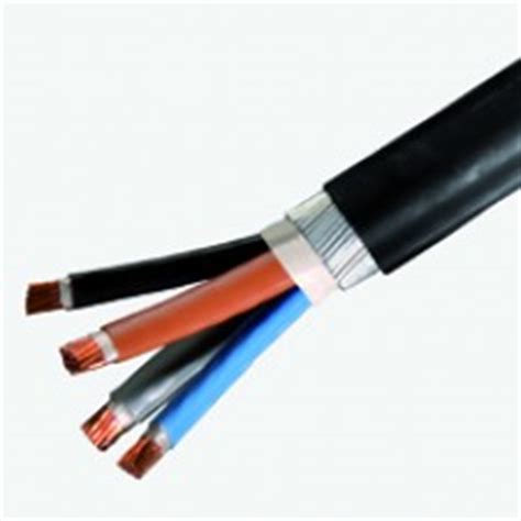
Prysmian FP600S is the ultimate fire resistant, armoured Low Voltage LV cable for power and control of emergency, life safety and fighting systems used in buildings.
Prysmian FP600S is the ultimate fire resistant cable for power and control of emergency, life safety and fighting systems used in buildings.
FP600S has been designed and developed for the most stringent British Standard fire test for cables, BS8491 F120 and meets or exceeds the fire resistance requirements of Category 1,2 and 3 which makes it suitable for power and control circuits as defined in BS8519:2010.
Prysmian fire resistant cable is featured on the LU – Approved Products Register approved by London Underground meeting the criteria for LU 1-085 and is suitable for use in Section 12 (underground and surface) applications.
BS 8519:2010
This British Standard and Code of Practice covers the selection and installation of fire-resistant power and control cable systems for life safety and fire-fighting applications.
BS 8519:2010 replaces BS 7346-6:2005, which is now withdrawn.
High-rise and complex buildings have developed in terms of increased size, height and complexity of active fire protection. This has allowed fire engineered solutions to be developed. These solutions require a high level of performance from the components of the building services, including the electrical supplies.
BS 8519 gives guidance and recommendations on the selection and installation of power and control cable systems. It covers systems that are required to maintain their cable circuit integrity for life safety and fire-fighting applications. It also gives recommendations for electrical system design for such applications, and recommended limits for survival times.
BS 8519 identifies those electrical loads defined as life safety and fire-fighting loads. It lists the factors to be considered by the engineer when selecting and specifying the performance requirements of the electrical distribution system needed to maintain integrity under defined fire conditions for a specified period, referred to as the fire survival time.
BS 8519 makes reference to the recommendations identified in BS 9999, with regard to the design and installation of the LV Low Voltage electrical distribution systems for life safety and fire-fighting equipment.
The British Standard also makes reference to 3 categories of circuits required to maintain their circuit integrity under defined fire conditions for varying fire survival times of 30 min, 60 min and 120 min. Appropriate cable tests are identified for each category derived from applicable British Standards that assess cable performance under conditions of fire as might be expected in an actual fire incident.
This standard aims to ensure that the level of circuit integrity is not compromised by other components of the whole electrical distribution system, including cable glands, terminations, joints and cable support and location systems including stainless steel cable ties.
BS 8519:2010 covers
- The source of supply
- The distribution voltage [high voltage (HV) or low voltage (LV)]
- The appropriate location of the main intake enclosures, HV switchrooms, LV switchrooms, transformer rooms, generator rooms, risers, fire life safety plant rooms and fire-fighting/evacuation lift motor rooms/shafts.

Prysmian FP600S also meets or exceeds low fire hazard requirements of LSOH cable.
Prysmian FP600S – The Ultimate Fire Resistant Armoured Power Cable
- 600/1000V Cable
- BS7846 F120
- BS8491 120 Minutes
- BS8519 Category 1,2 & 3 Power & Control Circuits
- BASEC Approved Cable
- LPCB Approved Cable
- London Underground Approved LU 1-085A (Previously ‘Section 12’)
Prysmian manufacture a range Fire Resistant cable accessories including cable cleats and cable glands to support the installation of FP600S cables.

Prysmian FP Cables – FP600S Fire Resistant Cables for Emergency & Essential Building Services
Why Degrade Cable Integrity By Installing Underspecified Cable Accessories?
Sub-standard cable accessories are often inadvertently installed forming weak links in many fire resistant cable installations. Plastic cable cleats and “budget” type cable glands only serve to introduce potential “flash-points” into cable circuits whose primary purpose is the safety and protection of people, assets and infrastracture in the event of a fire. For this reason Prysmian only recommend the installation of approved fire resistant glands, cleats and accessories.
The following tables should aid the contractor and specifier to selecting the correct FP cleats, glands and lugs.
PRYSMIAN FP600S FIRE RESISTANT CABLE – SINGLE CORE CABLES
The following selection table features the recommended cable accessories including claw cleats and cable glands LSF to support and terminate Prysmian FP600S cables – for the termination of the stranded copper conductors into control panels, enclosures, junction boxes and electrical equipment Cembre lugs can be used.
| Nominal Cross Sectional Area (sqmm) |
Approximate Overall Diameter (mm) |
Approximate Diameter Under Armour (mm) |
Nominal Diameter of Armour Wires (mm) |
Approximate Cable Weight (kg/km) |
Maximum Conductor Resistance at 20ºC (Ω/km) |
Short Circuit Rating (1 second) of Conductor kA |
Current Rating Three Phase AC Clipped Direct (Amps) |
Current Rating Three Phase AC Free Air or Perforated Tray (Amps) |
Volt Drop Three Phase AC (mV/A/m) |
Recommended Accessories |
| Claw Cleat Ref Number |
Brass Gland Ref Number |
| Three Core Cables |
| 4 |
21 |
15 |
1.25 |
800 |
4.61 |
0.57 |
42 |
44 |
10 |
370CG04 |
LSF25CW |
| 6 |
21 |
15 |
1.25 |
820 |
3.08 |
0.86 |
53 |
56 |
6.8 |
370CG04 |
LSF25CW |
| 10 |
23 |
17 |
1.25 |
1050 |
1.83 |
1.4 |
73 |
78 |
4.0 |
370CG05 |
LSF25CW |
| 16 |
24 |
19 |
1.25 |
1400 |
1.15 |
2.2 |
94 |
99 |
2.5 |
370CG05 |
LSF25CW |
| 25 |
29 |
22 |
1.6 |
2000 |
0.727 |
3.6 |
124 |
131 |
1.65 |
370CG06 |
LSF32CW |
| 35 |
31 |
24 |
1.6 |
2300 |
0.524 |
5.0 |
154 |
162 |
1.15 |
370CG06 |
LSF32CW |
| 50 |
32 |
25 |
1.6 |
2800 |
0.387 |
7.1 |
187 |
197 |
0.87 |
370CG07 |
LSF32CW |
| 70 |
36 |
29 |
1.6 |
3600 |
0.268 |
10.0 |
238 |
251 |
0.60 |
370CG07 |
LSF40CW |
| 95 |
40 |
32 |
2.0 |
4500 |
0.193 |
13.6 |
289 |
304 |
0.45 |
370CG08 |
LSF50SCW |
| 120 |
43 |
35 |
2.0 |
5400 |
0.153 |
17.2 |
335 |
353 |
0.37 |
370CG08 |
LSF50SCW |
| 150 |
48 |
39 |
2.5 |
6900 |
0.124 |
21.4 |
386 |
406 |
0.30 |
370CG09 |
LSF50CW |
| 185 |
52 |
43 |
2.5 |
8200 |
0.0991 |
26.5 |
441 |
463 |
0.26 |
370CG09 |
LSF63CW |
| 240 |
57 |
47 |
2.5 |
10100 |
0.0754 |
34.3 |
520 |
546 |
0.21 |
370CG09 |
LSF63CW |
| 300 |
62 |
52 |
2.5 |
12200 |
0.0601 |
42.9 |
599 |
628 |
0.185 |
370CG12 |
LSF63CW |
| 400 |
69 |
58 |
2.5 |
15000 |
0.0470 |
57.2 |
673 |
728 |
0.165 |
370CG13 |
LSF75CW |
| Four Core Cables |
| 4 |
21 |
15 |
1.25 |
800 |
4.61 |
0.57 |
42 |
44 |
10 |
370CG04 |
LSF25CW |
| 6 |
23 |
17 |
1.25 |
950 |
3.08 |
0.86 |
53 |
56 |
6.8 |
370CG05 |
LSF25CW |
| 10 |
24 |
19 |
1.25 |
1200 |
1.83 |
1.4 |
73 |
78 |
4.0 |
370CG05 |
LSF25CW |
| 16 |
27 |
20 |
1.25 |
1600 |
1.15 |
2.2 |
94 |
99 |
2.5 |
370CG06 |
N/A |
| 25 |
32 |
24 |
1.6 |
2400 |
0.727 |
3.6 |
124 |
131 |
1.65 |
370CG07 |
LSF32CW |
| 35 |
35 |
27 |
1.6 |
2800 |
0.524 |
5.0 |
154 |
162 |
1.15 |
370CG07 |
LSF40CW |
| 50 |
36 |
29 |
1.6 |
3200 |
0.387 |
7.1 |
187 |
197 |
0.87 |
370CG07 |
LSF40CW |
| 70 |
41 |
32 |
1.6 |
4500 |
0.268 |
10.0 |
238 |
251 |
0.60 |
370CG08 |
LSF50SCW |
| 95 |
44 |
36 |
2.0 |
5700 |
0.193 |
13.6 |
289 |
304 |
0.45 |
370CG08 |
LSF50SCW |
| 120 |
49 |
40 |
2.0 |
7300 |
0.153 |
17.2 |
335 |
353 |
0.37 |
370CG09 |
LSF50CW |
| 150 |
55 |
44 |
2.5 |
8600 |
0.124 |
21.4 |
386 |
406 |
0.30 |
370CG10 |
LSF63CW |
| 185 |
59 |
48 |
2.5 |
10500 |
0.0991 |
26.5 |
441 |
463 |
0.26 |
370CG11 |
LSF63CW |
| 240 |
64 |
54 |
2.5 |
12900 |
0.0754 |
34.3 |
520 |
546 |
0.21 |
370CG12 |
LSF63CW |
| 300 |
70 |
59 |
2.5 |
15500 |
0.0601 |
42.9 |
599 |
628 |
0.185 |
370CG14 |
LSF75CW |
| 400 |
79 |
66 |
3.15 |
20100 |
0.0470 |
57.2 |
673 |
728 |
0.165 |
370CG15 |
LSF85CW |
| Five Core Cables |
| 4 |
22 |
17 |
1.25 |
900 |
4.61 |
0.6 |
42 |
44 |
10 |
370CG05 |
LSF25CW |
| 6 |
24 |
18 |
1.25 |
1070 |
3.08 |
0.9 |
53 |
56 |
6.8 |
370CG05 |
LSF25CW |
| 10 |
27 |
21 |
1.25 |
1390 |
1.83 |
1.4 |
73 |
78 |
4.0 |
370CG06 |
N/A |
| 16 |
30 |
23 |
1.6 |
1900 |
1.15 |
2.2 |
94 |
99 |
2.5 |
370CG06 |
LSF32CW |
| 25 |
34 |
26 |
1.6 |
2500 |
0.727 |
3.6 |
124 |
131 |
1.65 |
370CG07 |
LSF40CW |
| 35 |
37 |
29 |
1.6 |
3100 |
0.524 |
5.0 |
154 |
162 |
1.15 |
370CG07 |
LSF40CW |
| Nominal Cross Sectional Area (sqmm) |
Approximate Overall Diameter (mm) |
Approximate Diameter Under Armour (mm) |
Nominal Diameter of Armour Wires (mm) |
Approximate Cable Weight (kg/km) |
Maximum Conductor Resistance at 20ºC (Ω/km) |
Current Rating DC or Single Phase AC Clipped Direct (Amps) |
Current Rating DC or Single Phase AC Free Air (Amps) |
Volt Drop DC (mV/A/m) |
Volt Drop Single Phase AC (mV/A/m) |
Recommended Accessories |
| Claw Cleat Ref Number |
Brass Gland Ref Number |
| Two Core Cables |
| 4 |
21 |
15 |
1.25 |
800 |
4.61 |
49 |
52 |
12 |
12 |
370CG04 |
LSF25CW |
| 6 |
21 |
15 |
1.25 |
800 |
3.08 |
62 |
66 |
7.9 |
7.9 |
370CG04 |
LSF25CW |
| 10 |
22 |
16 |
1.25 |
800 |
1.83 |
85 |
90 |
4.7 |
4.7 |
370CG05 |
LSF25CW |
| 16 |
23 |
17 |
1.25 |
1000 |
1.15 |
110 |
115 |
2.9 |
2.9 |
370CG05 |
LSF25CW |
| 25 |
26 |
20 |
1.25 |
1300 |
0.727 |
146 |
152 |
1.85 |
1.9 |
370CG06 |
N/A |
| 35 |
30 |
23 |
1.6 |
1800 |
0.524 |
180 |
188 |
1.35 |
1.35 |
370CG06 |
LSF32CW |
| 50 |
31 |
24 |
1.6 |
2200 |
0.387 |
219 |
228 |
0.98 |
1.00 |
370CG06 |
LSF32CW |
| 70 |
33 |
26 |
1.6 |
2600 |
0.268 |
279 |
291 |
0.67 |
0.69 |
370CG07 |
LSF32CW |
| 95 |
35 |
27 |
2.0 |
3400 |
0.193 |
338 |
354 |
0.49 |
0.52 |
370CG07 |
LSF40CW |
| 120 |
39 |
30 |
2.0 |
4100 |
0.153 |
392 |
410 |
0.39 |
0.42 |
370CG08 |
LSF50SCW |
| 150 |
42 |
33 |
2.0 |
4700 |
0.124 |
451 |
472 |
0.31 |
0.35 |
370CG08 |
LSF50SCW |
| 185 |
46 |
36 |
2.5 |
6100 |
0.0991 |
515 |
539 |
0.25 |
0.29 |
370CG09 |
LSF50CW |
| 240 |
51 |
41 |
2.5 |
7500 |
0.0754 |
607 |
636 |
0.195 |
0.24 |
370CG09 |
LSF50CW |
| 300 |
56 |
45 |
2.5 |
9000 |
0.0601 |
698 |
732 |
0.155 |
0.21 |
370CG10 |
LSF63CW |
| 400 |
61 |
50 |
2.5 |
11000 |
0.0470 |
787 |
847 |
0.120 |
0.19 |
370CG11 |
LSF63CW |
LV Cable Joints (Low Voltage Cables)
Thorne & Derrick stock and distribute LV Joints in Cold Shrink, Heat Shrink or Resin Cast technologies – multicore and multi-pair cable joints are available for immediate backfill and energisation of Low Voltage power, control and instrumentation cables 600V/1000V 3.3kV.
Complete range of LV Cable Accessories ➡
Cable Breakouts | Cable Caps | Cable Lugs | Cable Cleats | Cable Trough | Cable Duct | Feeder Pillars | for 11kV/33kV/66kV networks see MV HV Joints & Terminations

Insulated Gloves | Class 1 IEC 60903 Compliant Gloves
- Article by SP Energy Networks
The following information is contained with SP Energy Networks document OPSAF-12-025 Issue No.6: Insulated Gloves for Electrical Purposes Other Than HV Rubber Glove Working.
IEC 60903
IEC60903 produced by the International Electrotechnical Commission is an internationally recognised electrical safety standard: Live Working – Electrical Insulating Gloves.
IEC 60903:2014 is applicable to electrical insulating gloves and mitts that provide protection of the worker against electric shock.
This standard also covers electrical insulating gloves with additional integrated mechanical protection referred to in this document as “composite gloves“. The third edition cancels and replaces the second edition of IEC 60903, published in 2002 and constitutes a technical revision which includes the following major changes:
- clarification of the requirements and tests for long gloves
- introduction of a new special property for gloves resistant to leakage current
- removal of the requirement for an area to mark the date of inspection
- the d.c. electric tests are no longer included in the normative part of the document but a proof test is suggested at the production level in a new informative Annex E
- preparation of the elements of evaluation of defects, and general application of IEC 61318:2007
- introduction of a new normative Annex H on classification of defects
- introduction of a new informative Annex I on the rationale for the classification of defects
INSULATED GLOVES FOR ELECTRICAL PURPOSEs
SCOPE
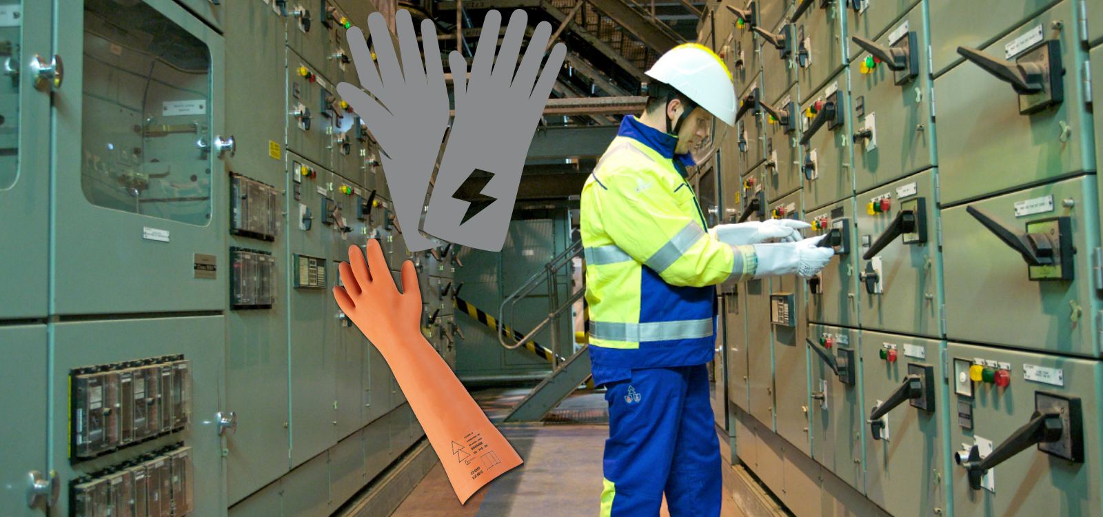
This section of the Energy Networks Live Working Manual (LWM) details the rubber gloves to be used by all persons who are required to work or test on, or in close proximity to, Live LV Conductors and for certain switching and testing activities on the Live HV System (up to 33kV). For Company employees it also describes the process for issue and replacement.
This document deals with gloves which comply with IEC 60903 (2014) Class 1.
The specification for the use and testing of rubber insulated gloves in connection with HV Rubber Glove Working is contained in OPSAF-13-001 (LWM 8.4) HV Rubber Glove Working techniques.
DEFINITIONS
Terms printed in bold type are as defined in the Scottish Power Safety Rules (Electrical and Mechanical) 4th Edition.
POLICY
Class 1 7.5kV insulated rubber gloves to the relevant IEC 60903 (2014) standard shall be issued to SP Energy Networks employees and its appointed contractors who are required to work or test on, or in close proximity to Live LV conductors. They are not meant to be the sole means of protecting those who work or test on Live LV conductors.
These IEC 60903 insulating gloves shall also be issued to personnel who are required to operate air-break switch disconnector handles, overhead Apparatus in substation outdoor compounds, link / fuse operating rods or to use moving-coil Approved voltage indicators on the HV System.
Pictured: Up to 36kV Air Break Switch Disconnectors
The Lucy Electric Rapier SAX Air Break Switch Disconnector range is compact and robust, providing a reliable, lightweight and flexible solution for network isolation and reinstatement. Incorporating a modular design switch that can be configured to suit a variety of applications, the range combines high performance and reliability and is particularly suited to rural environments.

Air-Break Switch DisconnectorS | 33kV 36kV Lucy Electric
Class 1 insulated gloves shall not be used for HV Rubber Glove Working on Live HV conductors.
Note: although Class 0 rubber gloves are rated for 1000V and would be appropriate for Live LV systems, experience has found them to be prone to damage when the gloves are not used with gauntlets. Class 1 gloves are thicker and more suitable to be worn without gauntlets if required.
Class 0 gloves shall not be used by SP Energy Networks employees or its appointed contractors on the SP Energy Networks System.
The SP Energy Networks specification TSE-03-044 for rubber gloves according to IEC 60903 require a high level of electrical arc flash protection. It is strongly recommended that insulating gloves provided by contractors provide an equivalent level of protection.
It is recommended that a leather protective outer gauntlet be used while operating on the HV System to prevent premature damage. Gauntlets shall be available for Persons with a preference to use them while working or testing on, or in close proximity to Live LV conductors.
Leather gauntlets also provide electrical arc protection which augments that provided by the rubber glove.
A protective wallet, to the relevant SP Energy Networks standard for the storage of rubber gloves shall be issued to all Persons issued with rubber gloves.
SP ENERGY NETWORKS GLOVE REPLACEMENT POLICY
This section describes the SP Energy Networks policy for replacement of damaged or time-expired insulating gloves to IEC 60903.
Contractors shall implement their own policy which may complement or differ from the Energy Networks policy.
The rubber insulating gloves shall be replaced before re-testing is required.
Class 1 7.5kV insulated rubber gloves shall be replaced twice per year, i.e. at 6 monthly intervals.
When the insulated gloves are first removed from the sealed bag in which they are delivered, the date of opening shall be written on each glove along the edge of the cuff using a ball-point pen or similar.
All IEC 60903 rubber gloves shall be replaced in pairs.
The leather gauntlets and protective wallet need not be replaced at the time of replacement of rubber gloves, but only as required.
At the time of replacement, all gloves shall be destroyed by having the fingers cut off. Gloves which exceed 12 months from the manufacturer’s test date shall be destroyed in the same manner.
Individual pairs of insulating gloves may be issued at other times as required.
Insulated gloves issued must have the manufacturers test date stamped on each individual glove. Insulated gloves shall only be in use within 12 months of the test date. Gloves shall not be in use for more than a 6 month period.
Insulated gloves remaining in the store, which have not been issued and have been stored appropriately, can be issued for the remaining duration of the 12 month period from the manufacturers test date as long as it does not exceed 6 months of use.
ORDERING
The quantities of IEC 60903 gloves required shall be determined far enough in advance of the period of issue to permit an order to be placed and delivery taken immediately prior to the period of issue.
If supply chain difficulties prevent delivery of adequate supplies of replacement gloves, the Operational Assurance Manager (or nominee) may approve a temporary extension of use.
STORAGE
IEC 60903 gloves shall be kept in store unfolded in the containers in which they are delivered. They shall be kept in dry conditions, away from strong light.
SAFETY REQUIREMENTS IN USE
When issued, but not in use, gloves shall be kept in the protective wallet, which shall be used only for storing the gloves. The wallet shall be kept away from moisture, strong light, and the risk of mechanical or chemical interference.
On each occasion before use, insulated gloves shall be examined by the user to ensure that they are safe for use. The examination shall include the following:
- Check that the manufacturer’s test date on the gloves is not more than 12 months old
- Check that gloves have not been in use for more than 6 months
- Check that gloves are clean and dry, both outside and in
- Check that the rubber does not show blisters or abrasions
- Stretch the gloves by hand and check for tears, cuts and punctures
- Complete an air test to confirm no punctures
- Replace immediately, if either of a pair of gloves shows signs of not being safe. Both gloves shall be replaced
If, as a result of the examination, either or both of the gloves is found to be unsafe, then the pair shall not be used.
PRECAUTIONS IN USE
Insulated gloves shall not be allowed to remain soiled or unnecessarily exposed to heat or light or allowed to come into prolonged contact with oil, grease, turpentine, motor spirit or strong acid.
Gloves shall be wiped clean on completion of work to remove any surface contamination.
When insulated gloves become heavily soiled, they should be thoroughly washed with soap and water then dried. If insulating compound such as tar or paint still adhere to insulating gloves, then those parts affected should be cleaned with approved cable cleaners or degreasant and then immediately washed and treated as described above.
Petrol, paraffin, or white spirit shall not be used to remove such compounds. Rinse the gloves with clean water after washing.
Any insulated glove, which becomes wet in use or through washing shall be thoroughly dried. Where heated air is blown into the glove, it shall not cause the temperature of the glove to exceed 55ºC.
IEC 60903
Insulated Gloves – Class & Category
The following gloves manufactured by CATU Electrical do not provide mechanical protection and must be used with silicon leather glove covers or over-gloves.
Insulated Gloves
Specialist Distributors Of LV MV HV Electrical Equipment
We supply Product Categories: Duct Seals | Cable Cleats | Cable Glands | Electrical Safety | Arc Flash Protection | Cable Jointing Tools | Cable Pulling | Earthing | Feeder Pillars | Cable Joints LV | Joints & Terminations MV HV

Transformer Bunds | Bunds for oil-filled transformers manufactured from steelwork on reduced lead time and at competitive prices from Thorne & Derrick | Contact us with your requirements | Stock, Service & Product Support
How Can We Help?
Thorne & Derrick can provide design and manufacturing services for Transformer Bunds with optional oil filters, drain valves, filter systems and ancillaries in both mild and galvanised steel (painted or unpainted) – innovative, efficient, safe and cost-effective solution for protection against leakages of insulating liquid to BS EN 61936-1:2010.
BS EN 61936-1:2010
Power Installations Exceeding 1kV a.c. Common Rules

Oil Filled Transformers
Guest Contribution: Carl A. Watkin IMEMME (Hons) I.Eng MIMMM MIET AIOSH
Carl has over 40 years experience as a Projects Director, Electrical Engineer & Project Manager in the highly regulated HSE HID hazardous and heavy industry sectors – this includes global ATEX and IECEx hazardous environment and area industries, civil tunnelling, LV MV HV utility sectors and the renewables sector.
In this original post from LinkedIn, the business and employment-oriented social media network, Carl discusses transformer bunds with gathered opinions from industry peers featured in the thread of comments below.
Bunding – Oil Filled Transformers
To Bund or Not To Bund?
by Carl A. Watkin
Question to all my fine Engineering contacts regarding oil filled distribution transformers – transformers are exempt from the UK oil storage regulations, as they are oil using (cooling) rather than storing, unless they have a conservator, holding in excess of 201lts, connected by single pipe – I see many transformer installs, including DNO installations, that do not have bunds around the transformers.
See: BundGuards | Substation & Transformer Oil Spills & Leaks Containment
What are your thoughts on bunding, or not, of oil filled transformers? What criteria would you use to assess whether to bund, or not?
➡ Neil Denbow (Director at Eden Transformer Oil). For distribution transformers yes you can but the process should be carried out by an accredited MIDEL Service Partner (we were the first). For power transformers yes but with referral to M&I Materials. There have been many successful retrofills around the world – MIDEL 7131

Contact Applied Power Engineering
➡ Manuel Bolotinha (Electrical Engineer). Usually sealed distribution transformers up to 630-800 kVA don’t need to be bunded.
➡ Neil Denbow (Director at Eden Transformer Oil). Manuel, BS EN 61936-1:2010 doesn’t differentiate between breathing and hermetically sealed transformers, it is defined by the volume of oil in the transformer.
➡ (Richard Emery IEng MIET MIHEEM Authorising Engineer (E) IHEEM AE(E) at Green Building Design Consultants). I get the transformer bunding problem, and even if you don’t have an oil storage problem, and the environment agency have incorrect information there is the risk assessment? Is a spillage going to cause secondary contamination, disruption and damage? How do we deal with external transformers/ bunding and rain water? I have seen some bunded walls with 300mm of water in them others with drain taps left on.
➡ Neil Denbow (Director at Eden Transformer Oil). Richard, larger 11kV transformers will have oil/water separation systems, smaller transformers will have valve with a oil/water capture filter that allows water to pass through but trap oil. We sell the latter on our website www.edenoil.co.uk and have a partner for the lager systems:- When a bund has not been maintained or doesn’t have filter system, we offer a bund emptying service.
➡ Dan James Technical Services Engineer (HV Senior Authorised Person at NG Bailey). We’ve put in from full on concrete swimming pools, active filters to perspex shields around the rads to stop fluid spraying past the bund. Most of the time midel is used these days which doesn’t have the same environmental issues, a bund with a filter seems to be what we do most though.
➡ Neil Denbow (Director at Eden Transformer Oil). Dan, you are right that MIDEL is readily biodegradable but BS EN 61936-1:2010 doesn’t differentiate between oil, synthetic or natural esters. However, insurance companies do.
➡ Craig Davies Senior Electrical Engineer – (Navitas Engineering Ltd) This has been debated many times in the Rail industry. With respect to Environmental Agency website error, certain parties in Rail industry have received same letter from Environmental Agency but certain representatives contradict each other in their response.
➡ Derrick Stableford P.Tech.(Eng.) (Electrical, Instrumentation and Controls Designer at Associated Engineering). Funny I had a containment question at work this week. Sorbweb matting would be my answer for leak control. Most trannys at this level have level switches as options, the hard part is the comms back to the control centre, without creating a cyber security intrusion risk. The sorbweb Mat adsorbs oil, and repels water. No need for a shed. Using food grade oil will also help with environmental risks. You could fry your lunch with a drawn off sample, or bang it in your diesel. The bunding and double wall systems have their own cost adders and maintenance issues, Inc water pump outs and disposal. Mechanical separators can freeze and fail, esp. here at severely minus temps.
➡ Craig Davies Senior Electrical Engineer – (Navitas Engineering Ltd). Thank you and I’ll have to research sorbweb matting.

Contact Applied Power Engineering
➡ Tony Haggis Director (Tony Haggis Consulting Ltd). Hazard control should follow the hierarchy: 1. Eliminate the hazard 2. Reduce the hazard 3. Control the hazard 4. PPE.
Pole transformers are not ‘reasonably practicable” to protect using HV fuses, particularly for LV side faults. Effective bunding is impossible. The most difficult zone is the tails from transformer to LV fuses. UK DNOs generally use double insulated single core cables fitted with plastic cleats and fixed to a wooden pole. LV fuses are single phase plastic units seperated 300mm apart, again, fixed to a wood pole. Phase to phase and earth faults are virtually impossible. Lightning takes out a lot of pole transformers causing them to explode oil over an area greater than any bund could catch. Again, the root cause is now well understood. A lightning induced flash over on the HV bushing causes the transformer tank to rise to more than 50kV. However, the LV winding is earthed separately from the HV earth and so the tank back flashes to the LV windings which fails resulting in a permanent LV side fault and transformer burnout. A simple 6kV lightning arrester fitted between the LV neutral and tank combined with a specified LV BIL (Basic Impulse Level) of 30 kV eliminates the problem. Also attention to LV fuse sizes and LV network look impedance significantly reduces burnouts due to uncleared LV faults.
➡ Karl R (Functional Safety & Systems Engineer). Watch out for an error in the HSE publicised “Hierarchy of Controls” leaflet. The vitally important area of physical isolation was missed. The hierarchy is actually: 1 Eliminate – do it a different way that doesn’t use the hazardous methods or substances. There’s no risk if there’s no hazard. No need to mitigate for a non existent hazard. Save effort, money and time for use elsewhere. 2 Substitute – use something non/less hazardous 3 Isolation – Physical separation. Barriers, bunds, locked areas and vessel containment. Dual layers. 4 Design – Automation, control, monitor, report and safely shutdown/reroute. Engineered solutions to mitigate hazardous situations and prevent hazardous material release. Control and safety systems to look after the process. Switchgear protection. 5 Admin – Enforcement and training. Emergency Response Procedures. Authorised areas, Competency, Risk Assessments, Design Reviews, Method Statements, verification and validation, maintenance, etc. 6 PPE
➡ Dale Smallshaw Managing Director (CRITICAL ELECTRICAL SOLUTIONS LIMITED) There’s a regulation in the 18th edition where it covers transformers containing oil shall be bunded or pitted to distinguish any potential fires
Thorne & Derrick stock and supply the DrainEezy range of transformer bund filters for use with LV MV HV Oil-Filled Transformers providing passive, self-regulating environmental protection and preventing bunds from overflowing during rainfall events; the DrainEezy Bund Filter System is field-ready to fit and retrofittable allowing clean water to drain freely while automatically blocking and retaining insulating oil in the event of a leak or catastrophic transformer failure.

600/1000V | 11kV | 33kV | 66kV Transformer Bund Filters

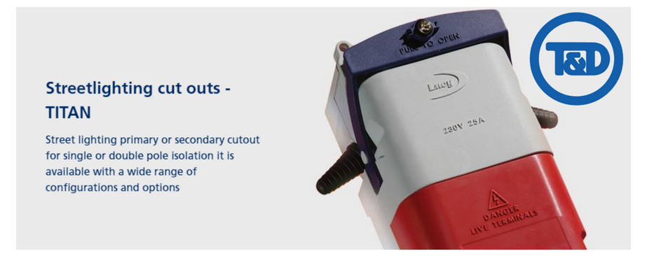
Street Lighting Cut Outs
Lucy Zodion Ltd, are the leading UK manufacturer of street lighting cut-outs, controls, feeder pillars and street lighting isolators – their street light cut outs (SLCOs) are also part of the G81 specification framework.
Lucy Zodion Titan2 cut outs are supplied as standard with features that ensure the street lighting technicians task is considerably easier.
The Lucy Titan2 cam lever handle enables effortless release of the Lucy fuse carrier in one movement and there is plenty of cabling space to terminate a wide variety of conductor types and sizes.
Insulated or brass cable gland plates are also available for when dual or triple entries are required.
High quality engineering thermoplastics make the Lucy Zodion Titan2 range the ideal choice to withstand heavy use in demanding locations.
Lucy Zodion Titan2
Street Lighting Cut Outs Range
- Single or double pole cut outs
- Single or twin fuse cut outs
- Brass or insulated gland plate options
- Extensive trough options
- 1 up, 2 up, 1 up 1 down circuit arrangements

Street lighting Cut Outs – Titan2
TITAN2 SINGLE & DOUBLE POLE CUT OUTS
PRODUCT SPECIFICATION
Should you require any technical support and advise in order to select the correct street lighting cut out please do not hesitate to contact us.
| Lucy Cut Out Part No |
Fuseways |
Components |
Description |
Cable Entry |
Image |
| Titan2 (NT06) double pole single fuse cut out, complete with earth block, and brass plate with: |
| THM0006032 |
1 |
2 x 20mm grommets |
NT06-TT-NG12 |
 |
 |
| THM0010170 |
1 |
2 x BW20 brass glands |
NT06-TT-NG18 |
|
| THM0010121 |
1 |
2 x 20mm tubes |
NT06-TT-NG25 |
|
| THM0031147 |
1 |
2 x 25mm tubes |
NT06-TT-NG26 |
|
| Titan2 (NT06) double pole single fuse cut out, complete with earth block, small extension trough, and brass plate with : |
| THM0010657 |
1 |
2 x 20mm grommets |
NT06-TT-NEF-NG12 |
|
 |
| THM0017257 |
1 |
2 x 20mm grommets |
NT06-TT-NEF-NG13 |
|
| THM0013678 |
1 |
2 x BW20 brass glands |
NT06-TT-NEF-NG18 |
|
| THM0010211 |
1 |
2 x 20mm tubes |
NT06-TT-NEF-NG25 |
|
| THM0010212 |
1 |
2 x 25mm tubes |
NT06-TT-NEF-NG26 |
|
| Titan2 (NT06) double pole single fuse cut out, complete with earth block, large extension trough, and brass plate with : |
| THM0036546 |
1 |
2 x 25mm grommets |
NT06-TT-NED-NG13 |
|
 |
| THM0037191 |
1 |
2 x 20mm tubes |
NT06-TT-NED-NG25 |
|
| THM0028975 |
1 |
2 x 25mm tubes |
NT06-TT-NED-NG26 |
|
| THM0016546 |
1 |
2 x BW25 glands and 1 x 25mm grommet |
NT06-TT-NEE-NG82 |
 |
| Titan2 (NT08) double pole twin fuse cut out, complete with earth block, and brass plate with : |
| THM0009901 |
2 |
2 x 20mm grommets |
NT08-TT-NG12 |
|
 |
| THM0012689 |
2 |
2 x BW20 brass glands |
NT08-TT-NG18 |
|
| THM0013303 |
2 |
2 x 20mm tubes |
NT08-TT-NG25 |
|
| THM0014521 |
2 |
2 x 25mm tubes |
NT08-TT-NG26 |
|
| Titan2 (NT08) double pole twin fuse cut out, complete with earth block, small extention trough, and brass plate with : |
| THM0010563 |
2 |
2 x 20mm grommets |
NT08-TT-NEF-NG12 |
|
 |
| THM0029334 |
2 |
2 x 25mm grommets |
NT08-TT-NEF-NG13 |
|
| THM0014659 |
2 |
2 x BW20 brass glands |
NT08-TT-NEF-NG18 |
|
| THM0011708 |
2 |
2 x 20mm tubes |
NT08-TT-NEF-NG25 |
|
| THM0010841 |
2 |
2 x 25mm tubes |
NT08-TT-NEF-NG26 |
|
| Titan2 (NT08) double pole twin fuse cut out, complete with earth block, large 2-way extention trough, and brass plate with : |
| THM0037298 |
2 |
2 x 25mm grommets |
NT08-TT-NED-NG13 |
|
 |
| THM0037316 |
2 |
2 x 20mm tubes |
NT08-TT-NED-NG25 |
|
| THM0037323 |
2 |
2 x 25mm tubes |
NT08-TT-NED-NG26 |
|
| Titan2 (NT10) double pole twin fuse cut out, complete with earth block, 3-way extension trough, and brass plate, with : |
| THM0027135 |
2 |
3 x 25mm tubes |
NT10-NED-NEE-NT6-NG61 |
|
 |
| THM0012093 |
2 |
3 x 20mm grommets |
NT10-NEC-NT6-NG68 |
|
| THM0010786 |
2 |
2 x 25mm grommets, 1 x 20mm grommet |
NT10-NEC-NT6-NG52 |
|
Lucy Zodion Titan2
Specifications
| Specifications |
- Designed and tested in accordance with BS 7654:1997 and IEC/EN 60947-Part 1
- Accepts fuses to IEC 269-1 and BS 88 Part 1, AC16 tag type
- Moulded in high performance thermoplastics
- IP43 rating
- Single or double pole cut outs
- Single or twin fuse
- Detachable terminal block in extension trough facilitates termination of heavy duty cables
- Electroplated brass terminal blocks accept conductors up to 25sqmm
- Terminal blocks for 1 to 3 conductors
- Stud and lug connections
- Serrated bores in terminals to ensure good contact with all conductor types
- Red terminal block cover for safety
- Brass or insulated gland plate options
- Padlock and sealing wire facilities provided
- Captive screw on cam lever
|
| Options |
- Single or Double pole
- Single or Twin fuse
- Brass or insulated gland plate options
- Extensive trough options
- 1 up, 2 up, 1up 1 down circuit arrangements
|

Lucy DNO Cut Outs Offer Street Lighting Contractors Improved Cable Termination Access
Lucy Lighting Titan SLF
Single Pole Cut Outs
With its low body split line to maximise cabling access, the Lucy Lighting Titan SLF is the simplest exponent of the single pole cut outs.
Tough, engineering grade thermoplastics and fully electroplated brass componentry ensure that the Lucy SLF street lighting cut out will have a long, reliable service life.
The Lucy Zodion Titan MC040SLF cam operated fuse handle ensures that electrical disconnection takes place prior to the fuse carrier being extracted by the street lighting contractor.
Lucy Zodion MC040SLF Single Phase Cut Out Specifications
- Cut out designed and tested in accordance with BS 7654:1997
- 25A maximum fuse rating
- Accepts fuse links to BS 88 Part 1, AC 16 tag type
- IP22 rating
- Single pole isolation
- Single fuse
- Electroplated brass terminals with serrated bores
- Max. cable size; 16sqmm stranded copper, 25sqmm solid aluminium
- Cable entry via PVC grommets as standard
- Outgoing cables exit below horizontal to form drip loop
- Sealing wire facility
| Lucy Zodion Titan MC040SLF Single Phase Cut Out Dimensions |
| Height |
150mm |
| Width |
76mm |
| Depth |
60mm |
| Order Details For MC040SLF Street Lighting Cut Out |
| Order Code |
Description |
| MC040SLF 25A SLCO TYPE 1 (SNE) |
Separate Neutral and Earth |
| MC040SLF 25A SLCO TYPE 2 (CNE) |
Combined Neutral and Earth |
➡ For further information about how Lucy Zodion provide control and power distribution products for street lighting applications, please review the Lucy Titan (Cut-outs) and Lucy Trojan (Isolators) ranges of products.
Complete range of LV Cable Accessories ➡
Cable Breakouts | Cable Caps | Cable Lugs | Cable Cleats | Cable Trough | Cable Duct | Feeder Pillars | for 11kV/33kV/66kV networks see MV HV Joints & Terminations


➡ James Hoare (LHW Partnership – Electrical & Energy Engineers). I thought the only way to get round was outdoor enclosure with class C or cast resin – when cast resin were first coming in they were welcome in buildings as an alternative to MIDEL as no need to bund the transformer.
➡ Neil Denbow (Director at Eden Transformer Oil). James, Class K insulating liquids such as the MIDEL range have the higher fire protection and are also readily biodegradable (unlike oil). However BS EN 61936-1:2010 doesn’t distinguish between the different liquids. By the way, as MIDEL Service Partners, we offer a mineral oil to MIDEL 7131 retrofill service. Click here for more information.
➡ James Hoare (LHW Partnership – Electrical & Energy Engineers). Neil – thank you – I used to work for GEC many …moons ago and we used to make distribution transformers dry and liquid – in those days Midel was a GEC group company so know it well . GEC became Alstom and think it’s now Schneider at this volts !!!
➡ Carl A. Watkin Neil, can you directly replace oil with MIDEL, one for one? I was told by Schneider that retrofit would involve fitting larger rads to the transformer as the volume of Midel required, per transformer KVA unit, to achieve the same cooling properties was higher?