Transport, Storage & Installation Recommendations for Halogen-free Shipboard Cables from Helkama
The purpose of this guide about Cable Drum Handling is to illustrate how cable damages can be avoided by correct handling and storage practices.
Handling Cable Drums
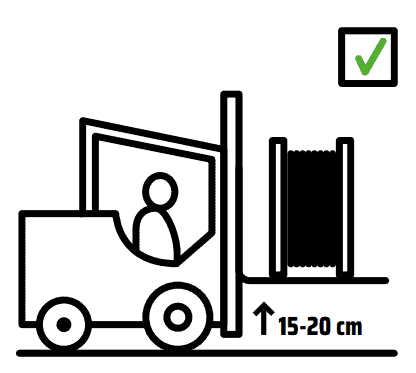
Drum flanges are marked to provide vital information to assist with the handling of the drums and the installation of the cable. This information includes drum weight, a mark on the flange indicating the end of the cable, and an arrow indicating the rotating direction of the drum for rolling or transportation. If the handling is done correctly, the drum will protect the cable from damages. The forks of the forklift must be longer than the width of the drum, so that the lagging is not damaged. Raise the forks of the forklift sufficiently (15-20 cm) above the ground.
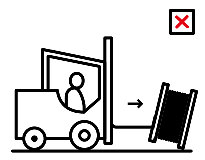
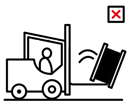
Insufficient cable drum lifting height may cause the drum to be dragged on the ground and eventually get damaged or dropped off the forks, especially if the ground surface is uneven. The drums may be placed and stacked on pallets to make it safer and easier to move them. Don’t push the drum with the forklift.
Storage of Cable Drums
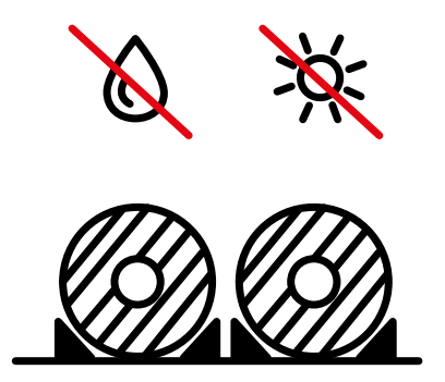
Cable drums shall be stored properly. Improper storage conditions can easily cause damage to cable drums or the actual cables. Cable ends shall be sealed with caps to prevent ingress of water. The caps must be protected to avoid any mechanical risk and exterior shocks. Always check drums before moving. Drums shall be stored on a level and firm surface (e.g. timber baulks, flange edges) standing upright and strapped/wedged securely to place. Do not store the drum with the flange flat on the ground.
Drums shall not be standing in water or be stored in continually damp conditions.
Failure to provide these conditions is likely to result in timber rot and weakening of the flange with potential breaking or collapse of the drum to the point where the cable will end up resting on the ground. Any of these outcomes will make later installation of the cablemore problematic or impossible.
Cables with coloured outer sheaths shall not be stored in direct sunlight to prevent fading.
Cables shall be protected against direct sunlight with suitable protective packaging, such as plastic sheeting. If the cable is used progressively (partial lengths are cut and used), the exposed cable end must be immediately sealed with a new end cap. Heat shrinkable end caps are recommended.
Packing of Cables
Before shipping the cable drums shall be packed correctly for transportation. The packing consists of the following items:
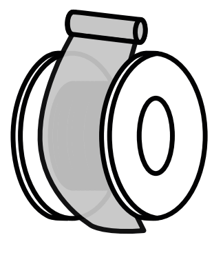
Plastic foil is wrapped over the cable layers and affixed with adhesive tape.
The cladding boards are attached with a plastic or steel strap (optional). Do not tighten the strap too much to avoid damage to the cable.
If the cladding boards need to be attached to the flanges of the drum with nails, the nailing shall be done making sure the nails hit the middle of the flanges, and don’t damage the outer cable layers.
Transport of Cable Drums
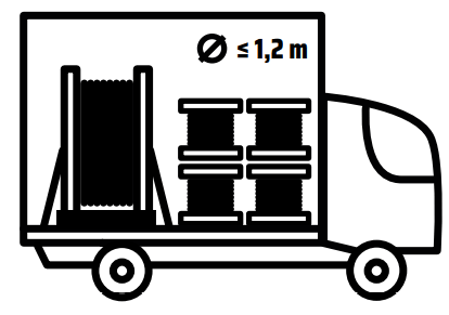
The bigger cable drums shall be loaded in the container or transportation vehicle in vertical position, i.e. standing up, so that they don’t move during transportation. For cable drums with diameter ≤ 1,2 m a horizontal position can also be used and the drums can be stacked.
Secure the drums firmly.
The round shaped cable drum rolls easily. Make sure that each drum is secured in place with stoppers/wedges to prevent rolling during transportation and storage.
During transportation, the drum shall be fastened with a combination of wedges and transportation straps to tie down the front and rear of the drum, to prevent movement of drums.
Lifting cable drums with a forklift is only allowed from the “flange side”. To avoid damage, never touch the cable or its protective cover with the fork.
Main dangers are the invisible damages that lead to unusable cables. Therefore some basic guidelines need to be followed. The cable itself must always be protected. Cable or drum, damaged by handling etc., must be checked before use.
The unloading and handling shall be done carefully using correct lifting equipment. When handling the drum with a forklift truck, place the drum vertically on the forks. Never let a drum fall during unloading.
Inspect the cables when they arrive on site. Check the condition of the end caps of the cables and the lagging (a break in the wooden lag could tear the outer sheath of the cable).
If the cable drums show signs of damage from handling and/or storage, any warranty obligation given for the cable drums and any subsequent problems resulting from it, are null and void.
Drums, cables and delivery documents must be inspected when the products are first received at the storage area. The packing list and the product order have to match the received products. In case of document flaws it is necessary to contact the nearest Helkama representative to assess the situation and advise an appropriate solution.
The received drums should be carefully inspected to ensure that no damage occurred during transportation. If any damage is discovered on the drum, it is advisable to also check the cable for damages. It is essential to inform Helkama representative if any cable damage or severe drum damage is found. The damage shall be documented before moving the drum in order to demonstrate the situation properly.
LONG-TERM CABLE STORAGE
Always inspect the drum before moving it from long-term storage.
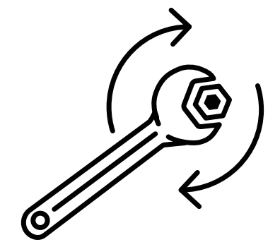
Transport vibrations and movement, weathering or environmental damage can cause changes in the drum and an assessment of the state of the drum is necessary. In changing dry and wet weather, or consistently dry and hot weather, the wooden sections of the drum can shrink and the whole drum could become unstable and cause damage to the cable when moving the drum. Therefore, the transverse bolts must be tightened with a torque wrench before the drums are moved, to prevent the drums from collapsing. To ensure the bolts stay tight they must also be re-tightened during cable installation.
Note that timbers of the drum flanges and barrels that have shrunk are also likely to have loose nails, but they are harder to fix than bolts. Apply caution and vigilance during the cable unwinding to identify loose nails and reduce possible damage to the cable.
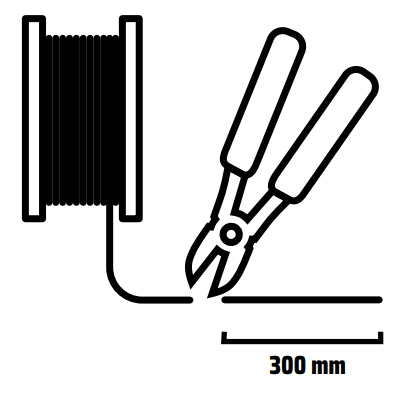
If the cable ends are accessible, it is recommendable to inspect the condition of the end caps. The end cap is designed to prevent the ingress of water. If the cap or seal has been absent for a long time (more than one month); or the cable end faces up toward the sky; or the end cap has been absent during periods of rain; or any form of cable end deterioration / ageing / swelling / or soiling is observed; it is recommended that the cable end be cut back 300 mm and re-examined for presence of moisture. If moisture is found, cut back further, and apply a new end cap to the cable end, ensuring a tight seal to the cable outer layer.
Installation Recommendations
for Halogen-Free Shipboard Cables
This document presents the guidelines for installing Helkama halogen-free shipboard cables. The guidelines are based on the standard IEC 60092-352 1) and on the experience from users.
Because the requirements of classification societies may differ, it is strongly recommended to get installation procedures approved by the classification society involved in each project.
CABLE SELECTION
Underground Cable Protection
Helkama halogen-free cables can be installed outside on open deck. If the cable will be exposed to heavy direct sunlight, it is recommended to use cable with black colour on outer sheath. Power and control cables with rated voltage 0,6/1 kV are black. Other cables are available in black on request. Another option is to paint the cables with water solvent paint.
CABLE PULLING
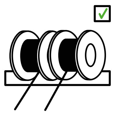
Only same size cables should be pulled at the same time. If different size cables (i.e. big difference in cable diameters) are pulled at the same time, the small cables may get damaged.
When pulling big cables, it is recommended to use cable rollers, especially if the cables are pulled with the help of cable pulling winches.
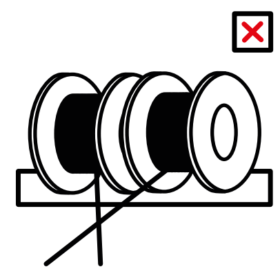
Cables should not be pulled crossing each other to avoid abrasion of the sheath at the crossing point.The number of cables to be pulled at the same time is determined by the installation conditions at site: distance to be pulled, open space available for looping the cable at intermediary drawing stations and the routing of cables (number of bends and number of corners).
PROTECTION OF CABLES DURING BUILDING OR REPAIR
Against welding sparks:
When welding close to cable drums or already installed cables:
The drum and cable should be protected against the welding sparks e.g. with a fire blanket or with a protection plate. A fire blanket is found to be very practical and easy to use.
Same methods can be used for the protection of installed cables.
Against abrasions on outer sheath:
Temporary cables used at the site (e.g. for welding and lighting) should not be pulled crossing already installed cables to avoid abrasion of the sheath at the crossing point.
MINIMUM CABLE BENDING RADIUS
The minimum bending radius during installation and for fixed installation shall be according to the following table.
Unarmoured & Unshielded Cable Types (LKM-HF AND LKMM-HF)
Diameter Range
During Installation
Fixed Installation
≤ 25 mm
6 x D
4 x D
Unarmoured & Unshielded Cable Types (LKM-HF, LKMM-HF AND LKM-FRHF)
Diameter Range
During Installation
Fixed Installation
≤ 25 mm
9 x D
6 x D
All Other Types
Diameter Range
During Installation
Fixed Installation
All sizes
9 x D
6 x D
MINIMUM INSTALLATION AND OPERATION TEMPERATURE
Minimum installation temperature for all cable types is –15 °C. Lowest operation temperature for all cable types is –40 °C.
CABLE FIXING
Cables shall be fixed by means of clips, saddles or straps of suitable material, which if ignited, will not contribute to any spread of flame along the cables or insulated wire. The material shall have a surface area sufficiently large and shaped so that the cables remain tight without their coverings being damaged. (IEC 60092-352 Clause 3.19)
As a guideline, the following recommendations can be given for straps (partly from Panduitweb-site):
Length of the Strap (mm)
Width of the Strap (mm)
Maximum Diameter of the cable bunch (mm)
102
2.5
22
142
3.5
35
188
4.8
48
292
4.8
75
371
7.6
102
510
12.7
130
718
12.7
200
The distances between supports shall be chosen according to the type of cable and the probability of vibration. It shall not exceed 400 mm for a horizontal cable run where the cables are laid on cable supports in the form of tray plates, separate support brackets or hanger ladders. The spacing between the fixing points may be up to 900 mm, provided that there are supports with maximum spacing as specified above. This exemption shall not apply to cable runs along weather decks, when the cable run is arranged so that the cables can be subjected to forces by water washing over the deck. (IEC 60092-352 Clause 3.19)
When designing a cable support system for single core cables, consideration shall also be given to the effects of electrodynamic forces developing in the occurrence of a short circuit. The distances between cable supports given above are not necessarily adequate for these forces.
Cables with class 5 conductors may require additional support to prevent sagging. (IEC 60092-352 Clause 3.19) The requirement above can be fulfilled by fixing the cables to each step of the cable tray or at maximum 400 mm intervals.
Fixed installation must be used when the cable is protected with a heat shrinkable sleeve. If there is a possibility that the cable outside the heat shrinkable sleeve may vibrate or move, the heat shrinkable sleeve must be long enough to be fixed on both ends.
Thorne & Derrick stock a wide range of Cable Cleats, Clamps & Hangers
REPAIR INSTRUCTIONS FOR HELKAMA HALOGEN-FREE SHIPBOARD CABLE OUTER SHEATH
If the cable has a damaged outer sheath, screen and insulation:
The whole cable has to be replaced.
If the cable has damages only (a hole or similar) on outer sheath, it can be repaired according to following instructions:
Wind tape (Scotch 70) around the cable with a little extension. Ensure the winding has 20-50 % overlap.
Set a shrink-on sleeve of flame retardant material over the taped length with 10 % overlap. Ensure that the diameter of the shrunk sleeve is correct.
Heat up with a hot-air blower, not with a fire blower. Start heating from the middle and work towards the ends.
If the cable has a deformation but the outer sheath of the cable is undamaged:
It may be difficult to determine if there is damage inside the cable.
It is difficult to know if the screen wires have deformed the cable insulation. The screen wires may have damaged the cable insulation and the insulation wall thickness may have decreased.
The characteristics will not be the same as for an undamaged cable.
If unsure, please contact the local representative of the classification society.
SPECIAL INSTRUCTIONS FOR LIGHT CABLES
Light cables include cable types LKM-HF L, LKSM-HF L, RFE-HF L, LKSM-FRHF L that are designed for applications where low weight and small size are required. Compared to standard cables, these cables are manufactured using smaller insulation and outer sheath wall thickness.
All the instructions in this document are also applicable to Light cables. In addition, using special caution is recommended in handling Light cables during cable pulling due to smaller outer wall thickness. IEC 60092-352 Ed.3.0 2009-9
Complete range of LV, MV and HV cable pulling products for installation and enabling cable jointing in trench or ducts including LV, 11kV/33kV medium voltage (MV), 66kV/132kV high voltage (HV) and EHV transmission and distribution cables up to 400kV.
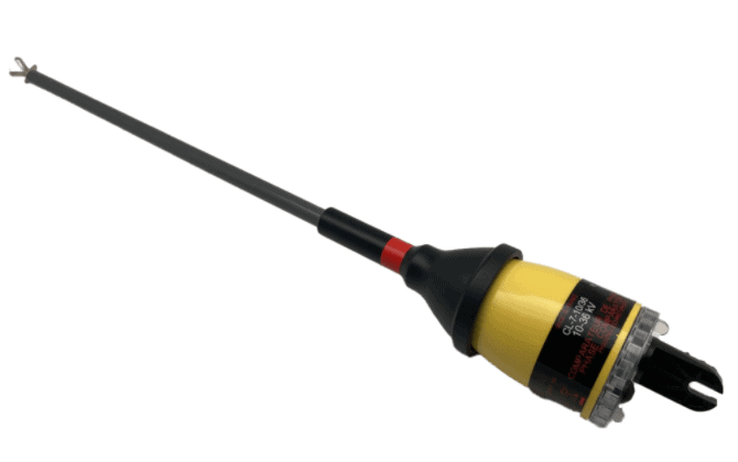
CATU has recently introduced a new single pole phase comparator, operating up to 36kV, to the Electrical Safety market. The CATUCL-7-4-18 is used to identify voltage differences between two points on 4kV and 18kV networks. Certified to IEC 61481-1 standards.
The new range of Phase Comparators are easy to use with user friendly features:
Single-pole device with C, K, W end-fitting
Storage of frequency and phase of distribution network voltages
Push-button test of the device, which also resets the memory
Class C: (maximum time for storing information in memory: 15 seconds when not connected to the line) . Non accordance (+110° to +250°)
LED indicators:
Orange (M) indicating the storage of a phase and the mains frequency;
Green (C) indicating that the mains phase is identical to the one previously stored (match); + discontinuous beep buzzer.
Red (I) indicating that the phase of the network is of a different phase from that previously stored (mismatch) + continuous beep buzzer.
Voltage difference between the two networks to be compared: +/- 15%.
Angle difference between the two phases (networks) to be compared: +/- 10°
The red ring indicates the physical limit to which the phase comparator can be inserted between live parts (57 cm from the red ring to the end fitting).
Option: Antenna Magnefix with a U Max utilisation : 18 kV, Order Ref C-921545
IEC 61481-1:2014
Live Working – Phase Comparators – Part 1: Capacitive type to be used for voltages exceeding 1kV a.c. Download IEC Standard.
CATU CL-7-4-18 HV Single Pole Phase Comparator with ‘K’ end fitting
CATU CL-7-4-18 Specification
CATU CL-7-4-18 is an HV single pole phase testing range with a buzzer and LED indicators.
These phase comparators are suitable to be used indoors and outdoors, where temperatures are between -25, and + 55°C (Climatic category – N). CL-7-4-18 is powered by a 6LR61 battery (9V).
Thorne & Derrick are national distributors of LV, MV & HV Cable Installation, Jointing, Substation & Electrical Equipment – servicing businesses involved in cabling, jointing, substation, earthing, overhead line and electrical construction at LV, 11kV, 33kV, 66kV and EHV. Supplying a complete range of power cable accessories to support the installation and maintenance of low/medium and high voltage power systems:
PICOUP 250 Hydraulic Spiking and Cutting Tool | Stocked in the UK by Thorne & Derrick | Cable Spikers
Hydraulic Cable Spiking & Cutting Tools
Spiking Cable | Check Voltage Absence on LV & HV Power Cables
The PICOUP 250and PICOUP 400 2 in 1 hydraulic cable spiking and cable cutting tools are used to check for and ensure the absence of voltage on LV MV HV underground power cables.
After the cable spiking process is complete, these PICOUP tools supplied by Thorne & Derrick can also be used to cut the cable. These tools offer total security to the user during application according to NFC 18510 standards.
Cable Spiking Tool Features
2 actions combined into one single tool (spiking and cutting)
Enables the user to limit any resulting short circuit to a single-phase / ground fault when spiking multi-core cables. This cause any protective devices to trip before a 2 or 3 phases fault can be created
In the event of spiking a live cable, the spiking blade can be replaced easily (minimising cost impact)
No physical connection between the tool and the user
Damage to infrastructure is minimised when spiking as a single phase to earth fault is created using a dedicated, local 70mm² copper earthing cable
Cutting failure sensor
Indication on the remote at the end of cutting operation
Hydraulic over-pressure safety valve
Battery charge status indicator
Prevents the start of cutting if the battery is low
MOS INDUSTRIE : 20 years of expertise
PICOUP 250 Hydraulic Spiking & Cutting Tool
The PICOUP 250 hydraulic spiking and cutting tool is supplied with flexible copper cable and earthing rod, two 24V batteries and quick charger, blade removal tool, 1 spare spike, two 2m straps for gallery work, a flash protection mat, a heavy duty waterproof case with carrying strap and laminated operating instructions.
Part Code
PICOUP 250
Manufacturer
Mos Industrie
Description
Safety hydraulic cable spiking and cutting tool
Cutting Capacity
ø 100 mm
Metal Armour
all except round wires
Maximum Section
3 x 240mm² copper
Cutting Force
13 000 kg
Autonomy
20 cuts
Factory Tests
10,000 cycles
Dimensions L x W x H
628 x 165 x 328 mm
Weight
14 kg
Flash Protective Mat
0.7 m x 1m
Packaging External Dimensions L x W x H
687 x 528 x 376 mm
Total Weight (including packaging)
35 kg
PICOUP 400 Hydraulic Cable Spiking & Cutting Tool
PICOUP 400 Hydraulic Spiking & Cutting Tool
The PICOUP 400 hydraulic cable spiking and cable cutting tool is supplied with flexible copper cable and earthing rod, two 24V batteries and quick charger, blade removal tool, 1 spare spike, two 2m straps for gallery work, a flash protection mat, a heavy duty waterproof case with carrying strap and laminated operating instructions.
Part Code
PICOUP 400
Manufacturer
Mos Industrie
Description
Safety cable spiker and cutter
Cutting Capacity
ø 140 mm
Metal Armour
Round wires 4mm
Cutting Force
21 000 kg
Autonomy
20 cuts
Factory Tests
10,000 cycles
Dimensions L x W x H
628 x 165 x 328 mm
Weight
20 kg
Flash Protective Mat
0.7 m x 1m
Packaging External Dimensions L x W x H
687 x 528 x 376 mm
Total Weight (including packaging)
42 kg
PB WEIR – DISTRIBUTORS, STOCKISTS & SUPPLIERS
PB Weir Substation Earthing and Transmission Line Earthing Equipment include line end clamps, earth end clamps, portable earthing leads and operating poles for high voltage substations, overhead power line and transmission line applications – voltages include 11kV, 33kV, 66kV, 132kV up to 400kV.
Thorne & Derrick provide competitive prices and fast delivery from stock for the complete range of PB Weir substation earthing and transmission line earthing equipment.
In 2018 In 2018 PB Weir joined the Novarc group and re-branded as PBwel and now, through the ESP group of companies, we are able to supply, support and maintain a comprehensive range of Electrical Safety Equipmentwhich includes: Earthing, Insulated Tools, Arc Flash Protection, Personal Voltage Detection Helmets, Insulating Gloves, Voltage Detection, Operating Poles & Lock-Out Tag-out.
ALADIN| Improved electrical safety levels for workers operating near live equipment
Thorne & Derrick International are specialist distributors of LV, MV & HV Cable Installation, Jointing, Duct Sealing, Substation & Electrical Equipment – servicing UK and global businesses involved in cable installations, cable jointing, substation, overhead line and electrical construction at LV, 11kV, 33kV and EHV.
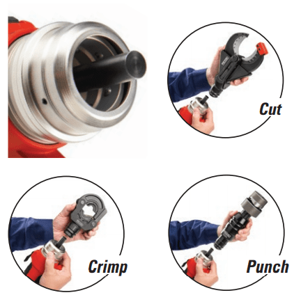
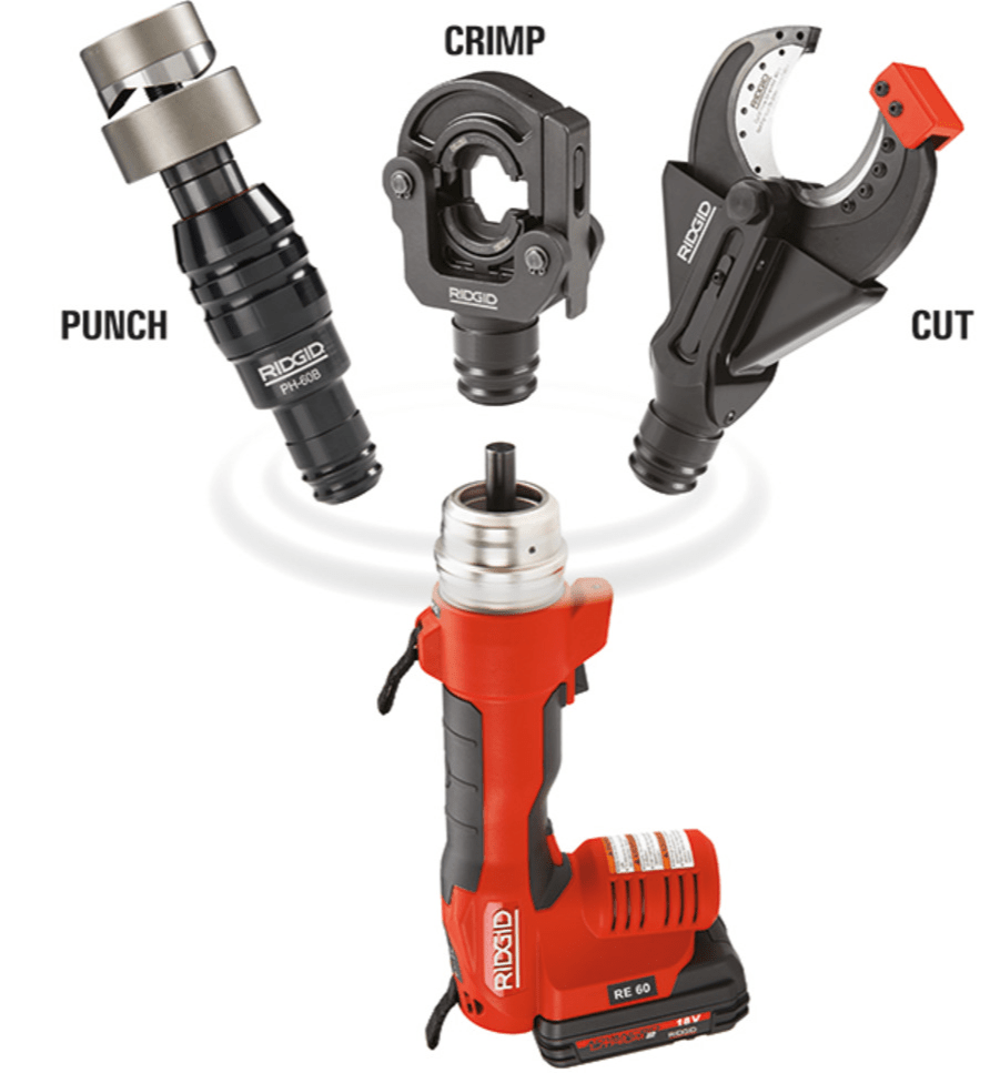
Now there’s a more efficient way to cut, crimp, and punch on the jobsite. The new line of RIDGID electrical tools, the RE 60, features the unique QuickChange System, allowing you to quickly and easily switch between interchangeable heads for cutting, crimping and punching. Now your important tasks can be accomplished with one innovative tool.
Whether you are cutting wire, crimping lugs or punching boxes, the RE 60 helps you to maximize productivity and efficiency on the jobsite. Your most critical electrical tasks are brought together in one convenient tool.
RIDGID RE 60 features a 6-ton (60 kN) hydraulic force output to cut armoured cable up to 50 mm O.D., crimp Cu/Alu cable lugs up to 300 mm² and punch round holes up to 63,5 mm. During cutting and crimping, the ram will automatically retract once the cycle is completed. Punching applications require use of the release trigger.
The built-in sensors and LED indicators ensure tool performance, allow the tool to operate in extreme temperatures (-10° -50°C), monitor cycle time, generated pressure, battery life and indicate when the tool requires service.
RIDGID RE 60 TOOL
Features
60 kN force output for crimping lugs up to 300 mm², cutting cables up to 50 mm diameter and punching holes up to 3 mm mild steel.
Automatic ram retraction when cutting and crimping
Longest service interval in the industry (32.000 cycles)
360° head rotation
Bright white LED for illuminating the workspace
Rubber over-molded grip for superior comfort and control
Nylon straps for greater tool security
Heavy-duty, blow-molded case for easy transport and storage
On/Off button for disabling tool when changing dies or heads
Powered by the RIDGID 18V Advanced Lithium battery platform
RIDGID RE 60 Featuring the RIDGID QuickChange System
RIDGID RE 60 TOOL
Specifications
Order Code
RIDGID RE 60
Manufacturer
RIDGID Tools
Description
RE 60 Electrical Tool Kit w/SC-60B Scissor Cutter, LR-60B Latching Round Crimp Head and PH-60B Punch Head
Approximate Cycle Time
5 seconds
Service Interval
32,000 cycles
Weight
3.2 kgs w/battery
RIDGID RE 60 3-in-1 Electrical Tool
See how T&D support, supply and service the Renewable Energy industry.
Thorne & Derrick are Specialist Distributors to the UK and international Offshore Wind & Renewable industry to provide safe and reliable LV HV Electrical Cable & Power Distribution Systems up to 66kV – we are highly customer responsive and absolutely committed to providing a world-class service.
Contact our UK Power Team for competitive quotations, fast delivery from stock and technical support or training on all LV-HV products.
Thorne & Derrick distribute the most extensive range of Low & High Voltage Cable Installation & Electrical Distribution Equipmentto the Power Transmission & Distribution industry in the onshore and offshore wind, solar, rail, oil/gas, data centre, battery storage and utility sectors – this includes Arc Flash Garments & Clothing to provide protection against the dangers of arc flash risks to workers carrying out maintenance, inspection and repair on electrical power systems.
We service UK and international clients working on underground and subsea cables, overhead lines, substations and electrical construction at LV, 11kV/33kV up to EHV transmission and distribution voltages.
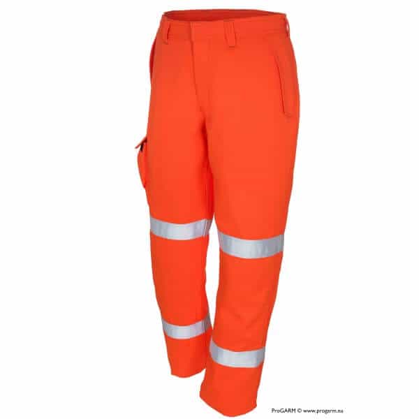
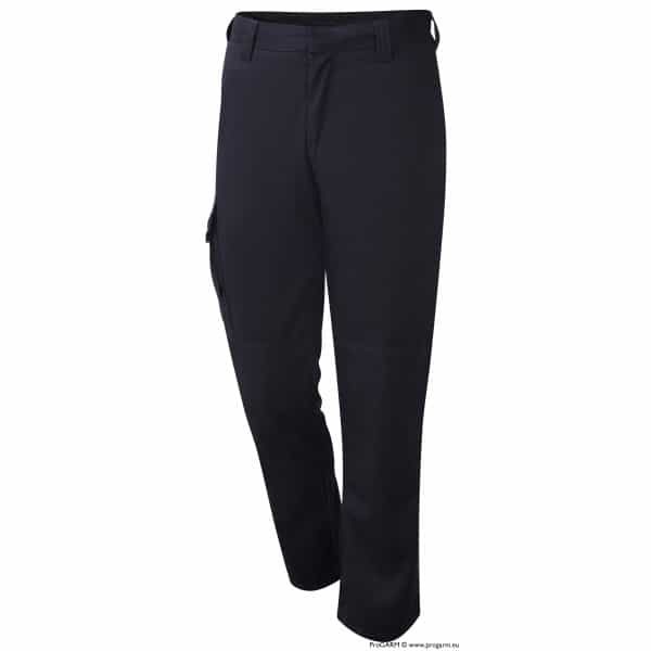
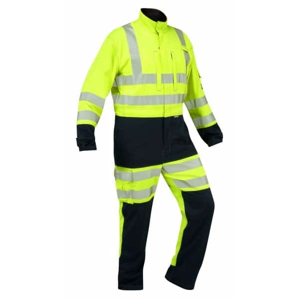
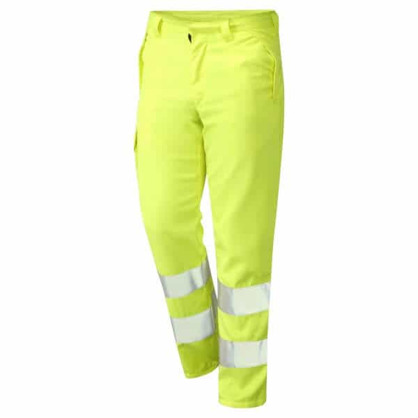
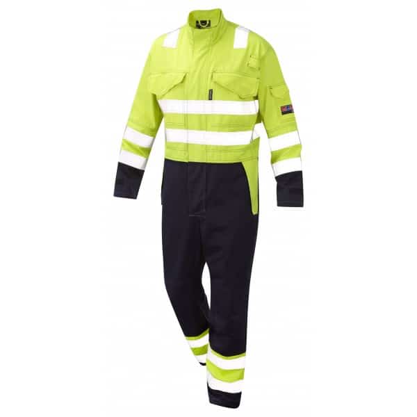
The following items comprise the current Top 10 Sellers from our extensive ProGARM range of Arc & Electrical PPE for arc flash and flame resistant protection of utility workers.






 The number of cables to be pulled at the same time is determined by the installation conditions at site: distance to be pulled, open space available for looping the cable at intermediary drawing stations and the routing of cables (number of bends and number of corners).
 MINIMUM INSTALLATION AND OPERATION TEMPERATURE








 RIDGID RE 60