

Blog
Cable Pulling Equipment – A Cable Laying, Duct & Installation Guide From SSE
February 1st, 2018
Thorne & Derrick | Cable Pulling & Laying Equipment Stockists and Suppliers
-
by Chris Dodds T&D - estimated reading time 2 minutes
Cable Pulling
The following information based upon a document produced by UK DNO, Scottish & Southern Electricity Networks, provides information and guidance on New Connections and best practise for cable pulling and laying and when installing LV (Wavecon | Concentric), 11kV (3 Core | Single Core) and 33kV (Single Core) cables into underground cable trenches.
The cable pulling equipment for ensuring safe and compliant installation of LV-HV cables up to 33kV is briefly outlined – should you require any further information or technical support please contact us.
All work carried out and cable pulling equipment used must be compliant with SSE technical guidance (TG-PS-881) available from the SSEN website.
It is also recommended that contractors and clients review the ‘Practical Guide to Streetworks’ before undertaking any excavations prior to installing LV-HV cables to form part of new connections.
The following cable trench section shows the position of cable and the cable duct in the ground – it is important that the top of any apparatus is at these depths as a minimum, this includes the top of the cable duct. In addition to the cable or duct there is a requirement for 75mm finefill material on all sides. Cable marker tape or cable tiles/covers must be installed 150mm above the top of the apparatus, this needs to have SSEN branding on.
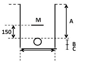
This table shows the minimum depths to top of apparatus (A within the diagram above)
| Minimum Apparatus Depth | Unmade Ground, Verges & Footway (mm) | Carriage (Road) (mm) | Agricultural (mm) |
| Cables LV | 450mm | 600mm | 1000mm |
| 11kV Cables HV | 600mm | 750mm | 1000mm |
| 33kV Cables HV | 800mm | 900mm | 1100mm |
Minimum Excavation depth required = (A) minimum depth of apparatus + (B) outside duct/cable size + (C) 75mm of sand bedding.
Please note that (M) represents the cable marker tile (for 33kV cables use Stokbord covers) or cable protection tape for all other installations including 11kV cables and cable joint protection.
Please note: Where there are sudden changes in surface type (e.g footway to carriageway), excavations should always be at the greater of the depths required.
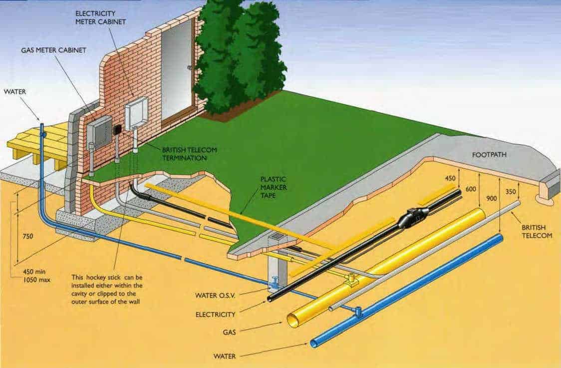
New Housing Service Cable Installation Guide
Experience has shown that by using a service tube the disturbance to the site is reduced when the electricity supply is connected.
The service tube can be laid in the same cable trench as the other services are shown, with an identifying plastic cable marker tape installed above to give advanced warning of service cable location on private property.
External meter cabinets
The external meter cabinets must be positioned in agreement with SSE to provide unrestricted access.
The preformed ‘hockey sticks’ can be installed either within the cavity or clipped to the outer surface of the wall below the meter cabinet.
White ‘hockey sticks’ must be used on the outer surface of walls. The service tubing must be securely coupled to the ‘hockey sticks’. The cabinets are only large enough to house SSE service and connection equipment.
Clients must fit own main switches on an inside wall so that the length of interconnecting cable does not exceed 3 metres.
This cable must only enter through the bottom of the cabinet, using the right hand hole, when viewed from the front.
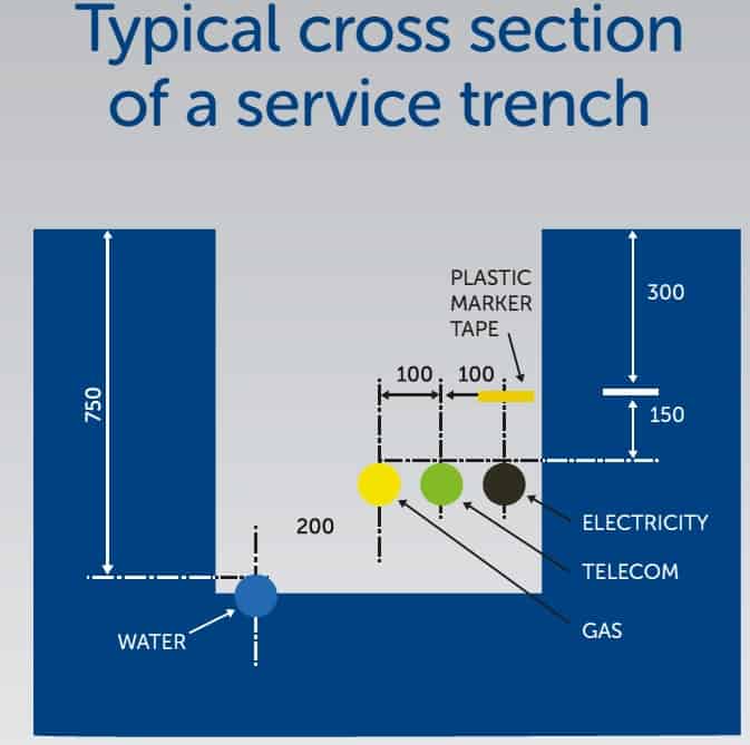
Typical Cross Section of A Service Trench
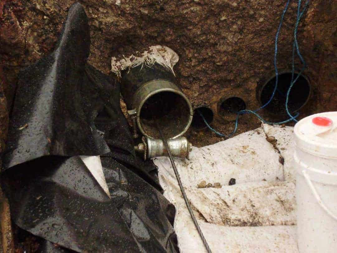
Duct Seals – contact us for duct sealing solutions and products to provide sealing against water (flood prevention) to copper and ducted low, medium and high voltage power cables.
Installation of Cable ducts
For the installation of ducted schemes the use of Black electric cable ducts only (see table below for approved suppliers) are permitted for use.
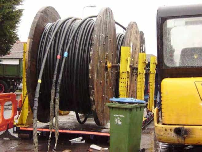
Clients should consider the type of cable ducts intended to use before ordering as excavations will be different depending on which cable duct supplier you use – the minimum cable bending radius must also be considered by referring to the manufacturers specification and selecting the appropriate cable pulling equipment to include cable rollers, socks, drum jacks and cable winches.
Emtelle cable duct range includes a smooth bore type of ducts which have rigid preformed bends at differing angles. When pulling and laying cables it is important that angles or bends should not be placed too close together otherwise cable pulling tensions will become greater than the manufacturers guidelines during the installation process.
Winch Cable installation
All cable must be installed not exceeding the manufacturers recommended cable pulling tensions – this applies to low, medium and high voltage power cables. Contractors must familiarise themselves with these cable pulling loads before hiring the equipment to ensure that these loads are not exceeded.
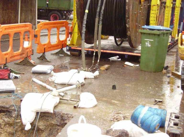
For all Cable Pulling applications contractors should use the following cable laying equipment and products:
- Cable winch
- A display of the cable pulling tension on the winch (calibrated)
- A free moving cable pulling swivel link
- Cable rollers located typically every 4 metres and/or where LV-HV cable would come into contact with ground
- Cable socks to ensure excellent grip and support of LV-HV cables
In addition to cable trench installations, for ducted cable schemes you will also need;
- Bell mouth roller
- Cable lubricants
- Cable drum trailers for each cable drum
For 33kV single core cables it is recommended that the contractor put colour indicators on each cable for identification – the cable installer must securely anchor the cable drums and the cable winch at either end and ensure that the LV-HV cable does not come into contact that could inflict cable sheath damage.
Cable Socks – high tensile strength galvanised steel cable socks provide support and grip for LV-HV cable pulling into duct or laying into trench.
Cable Pulling Equipment
Cables, Duct, Duct Seals & Cable Tiles Approved Equipment
| Item | Manufacturer | Manufacturing Location | Notes |
| LV Concentric Cables | Tratos | UK | |
| Cabelte | Portugal | ||
| LV Wavecon Cables | Prysmian | Wrexham UK | |
| Hellenic | Greece | ||
| 11kV Three Core Cables | Nexans | Hannover, Germany | Aluminium stranded & solid conductors 11kV |
| Prysmian | Wrexham UK | ||
| 11kV Single Core Cables | Tele-Fonica Kable | Poland | Copper or aluminium stranded for all conductor sizes Solid aluminium up to and including 300sqmm conductors 11kV |
| Prysmian | Wrexham UK | ||
| Nexans | Hanover, Germany | ||
| 33kV Single Core Cables | NKT | Cologne, Germany | Copper or aluminium stranded for all conductor sizes 11kV or
Aluminum stranded for all sizes or solid aluminium up to and including 300sqmm |
| Tele-Fonica Kable | Poland | ||
| Prysmian | Wrexham UK | ||
| Nexans | Hanover, Germany | ||
| Cable Duct | Polypipe Civil Ltd | UK | |
| Emtelle UK Ltd | UK | ||
| Cable Tile | Centriforce | UK | |
| Cable Warning Tape | Centriforce | UK | |
| Plastic Tape Tile | Centriforce | UK | |
| Duct Seals | TE Connectivity | UK | Rayflate Inflatable Cable Duct Seals |
| WT Henley | UK | Services Ducts (Green Plastic Compound) | |
| Winn & Coates (Denso) | UK | Denso Mastic Denso Tape |
|
| CSD Cable Sealing System | UK | CSD RISE Cable Duct Sealant System |

Joints | Terminations | Glands | Cleats | Cables | Tools | LV MV HV 11kV 33kV
Cable Laying & Pulling Equipment
Thorne & Derrick distribute an extensive range of Cable Laying & Pulling Equipment to enable the safe installation of utility power cables including LV Waveform and MV-HV Power Cables 11kV/33kV – full range of cable spiking tools available to ensure LV-HV power cables are dead prior to jointing or cable termination works.

➡ Further reading: Cable Pulling Equipment – A Cable Duct Laying Guide From BT Openreach
Cable Pulling Equipment – A Cable Duct Laying Guide From BT Openreach
February 1st, 2018
Thorne & Derrick | Cable Pulling & Laying Equipment Stockists and Suppliers
-
by Chris Dodds T&D - estimated reading time 5 minutes
Cable Pulling
The following information produced courtesy of a BT Openreach document provides a quick guide to duct laying and the Cable Pulling Equipment required to install cables into underground cable ducting.
Where the Openreach cable duct crosses a carriageway adjoining kerbs must be temporarily marked to note positions. Openreach duct needs to be laid on an outer edge of the service trench to enable box building. The contractor will need to insert a draw rope through the duct and secure it to the marker posts at both ends of the crossing. The appropriate Plug Duct 4B socket end and 4C Spigot must be fitted.

PVC Cable Duct For Underground Telecom Cables | Openreach
Duct beneath a carriageway crossing must be laid at a depth of 600mm from the cover of the final surface levels. For engineering reasons (National Joint Utilities Group NJUG) it must be separated from other services laid in parallel by 600mm (to permit Openreach to install underground joint boxes without the need for bends). Cable marker no.2 is needed at the site entrance boundary to ensure link up identification for cable contractors.
The latest information on the positioning of utilities, mains and plants can be obtained from the National Joint Utilities Group.

Cable Ducting
- All cable runs must be laid as straight as possible for installation into duct using correct cable pulling equipment
- If required bend the cable ducts or use pre-formed duct bends supplied by Openreach
- There can be no more than one pre-formed 90° cable duct bend in any single run of duct
- Pre-formed 90° cable duct bends cannot installed in any duct linking two joint boxes
- Footpath or service strip ducting must be laid at 350mm depth of cover
- All space alongside the cable duct must be backfilled with granular fill to a minimum thickness specified by Openreach
- For all Single Dwelling Units (SDU) cable duct must be terminated on the external surface of the property
- The duct termination point shall be in a location that will allow unrestricted access for any future maintenance activity
- All cable ducts must be provided with a draw rope after installation, unless it’s agreed locally to substitute the draw rope with a cable
- Please notify the field based coordinator (FBC) when the duct has been laid and is ready for inspection.
Typical issues with carriageway road crossings
- Insufficient depth
- Proximity to other services
Impact of issues
- Renew duct – this may delay any first occupation date or subsequent occupation dates.

Press Release | Thorne & Derrick Appointed Approved Stockist for UK Leading Cable Pulling Equipment Manufacturer
Avoiding Damage to the Openreach Underground Network
Openreach has an extensive underground network of ducted cables that can be located inside or on the perimeter of a site. The network is vulnerable to excavation related damage unless appropriate measures are taken. The precautions for avoiding damage to an underground utility plant are contained within the Health & Safety Guide No. 47: Avoiding Danger From Underground Services (download below).
This document stresses the need for available utility plans on site and the use of safe digging practices.
Third-party damage to the Openreach network can be expensive for that party to repair.
- Direct cost – the cost of repair
- Operational cost – delays associated with repair
- Social cost – loss of service to emergency services/centres or the vulnerable in society
💡 TIP: Use Openreach “Click Before You Dig” service – a proven record of minimising the potential for damage and cost.
If you locate damage on site you should contact your FBC immediately.
If outside the perimeter of your site and has the potential to be a danger to the general public please contact Openreach by calling 0800 023 2023, Option 1, Option 1.
Duct Seals – contact us for duct sealing solutions and products to protect and provide sealing against water (flood prevention) to copper and fibre ducted cables.
Cable Pulling Equipment
Thorne & Derrick distribute an extensive range of Cable Pulling & Laying Equipment to enable the safe installation of fibre and copper cables within the telecommunications industry. Safely installed cables reduces operational and maintenance requirements to the network and reduced service interruption to telecom cables, wires, ducts, cabinets and exchanges – products include cable spiking tools, conduit rods, cable lubricant, cable socks and rollers.
➡ Further reading: Cable Pulling Equipment – A Cable Laying, Duct & Installation Guide From SSE
Fire Resistant Blanket – Protecting LV MV HV Cables & Joints Against Fire
February 1st, 2018
Fire Resistant Blanket – Nexans NX-FIRE
-
by Chris Dodds T&D - estimated reading time 2 minutes
Nexans
Nexans Fire Resistant Cable Blanket is a cable joint protection cover with belts designed to be used with LV, MV or HV joints and cables in applications where low smoke emission and resistance to fire is needed. The Nexans Fire Protection Kit is designed for easy installation due to the belt design, open shape and “wrap-around” installation application.
The fire resistant cable blanket is designed with different layers of material to withstand high temperatures and is suitable to protect low, medium and high voltage cables from the destructive effects of fire. No specialist tools are required to install the fire blanket – simply manually lift, tighten and fasten the lightweight blanket onto the cables.
All materials included in the Nexans Fire Protection Kit are classified as low smoke emission and halogen free.

Protecting LV MV HV Cables & Cable Joints Against Fire
Nexans NX Fire blanket has been approved by ENEL and is available in different sizes and lengths upon request to suit cable outside diameters 20-300mm.
Nexans NX Fire – Technical Data
| Nexans Part Number | D Min (mm) | D Max (mm) | Length (mm) | Side 1 | Side 2 |
| NX-FIRE 1.11 | 20 | 85 | 1100 | 1 Core | 1 Core |
| NX-FIRE 2.11 | 50 | 170 | 1600 | 1 Core | 1 Core |
| NX-FIRE 3.11 | 100 | 300 | 2000 | 1 Core | 1 Core |
| NX-FIRE 2.13* | 50 | 170 | 1600 | 1 Core | 3 Core |
| NX-FIRE 3.13* | 100 | 300 | 2000 | 1 Core | 3 Core |
*Special version for transition cable joints. Available upon request
Fire Resistant Blanket – Application
 |
 |
 |
| 1. Position the fire resistant blanket at the centre of the cable joint or cable | 2. Wrap the fire resistant cover around the cable joint or cable | 3. Tighten the belts to ensure that the fire protection blanket is held firmly in place onto the LV-MV-HV cable |
Onshore or Offshore
Used to protect both onshore and offshore cables, including offshore cable joints where marine and offshore cables and joints in fixed installations for power circuits, emergency lighting systems and fire alarm systems must provide continued service in fire conditions.
The product is cold-applied without need to resort to “hot-work” permit applications to carry out cable repair, jointing or protection in potentially explosive atmospheres or hazardous area locations.
Underground Or Overground
Suitable to provide fire protection to fire hazard safety cables in the rail industry – including sub-surface, tunnels or station level including power cables for low voltage lighting, fire detection, emergency, signalling and auxiliary circuits.
International Standards
The fire resistant blanket has been tested according to the following international standards:
- IEC 60332-3-22 cat. A (fire propagation test)
- IEC 60331-11 & 21 (fire resistance test)
- BS 6387 cat. C (fire resistance test)
- IEC 61034-1&2 (low smoke emission)
- BS EN50268-2:2000 / BS 6853:1999 Annex B.2 (Low Smoke and Toxic emissions)
NEXANS CABLES & ACCESSORIES
To support the installation of MV-HV cables, T&D distribute the Nexans Power Cable Accessory range – this includes heat shrink terminations and cold shrink cable joints and the Euromold range of screened separable connectors extensively installed to terminate MV-HV power cables.
- Slip-on Cable Terminations
- Cold-shrink Cable Terminations
- Heat-shrink Cable Terminations
- Cable Joints – Heat & Cold-shrink
- Separable Connectors (Euromold)
- Surge Arresters & Switchgear/Transformer Bushings
MV-HV Cable Joints, Terminations & Connectors suitable for connecting, repairing and extending 11kV and 33kV high voltage power cable circuits.
THORNE & DERRICK are national distributors LV, MV & HV Cable Installation, Jointing, Substation, Earthing & Lightning Protection & Electrical Equipment – we service UK and global businesses involved in cable installations, cable jointing, substation, overhead line and electrical construction at LV, 11kV, 33kV and EHV.

Since 1985, T&D have established an international reputation based on SERVICE | INTEGRITY | TRUST.
Contact us for 3M Electrical, ABB, Alroc, AN Wallis, CATU Electrical, Cembre, Centriforce, CMP, CSD, Elastimold, Ellis Patents, Emtelle, Euromold, Filoform , Furse, Lucy Electric & Zodion, Nexans, Pfisterer, Polypipe, Prysmian, Roxtec, Sicame, WT Henley.

Invitation
Thorne & Derrick invite you to join LinkedIn’s largest LV-HV Electrical Discussion Group : Low & High Voltage Power, Cabling, Jointing & Electricals. Discussion subjects include cable installations, cable jointing, substation, overhead line and electrical construction at LV, 11kV, 33kV and EHV. Network, engage and promote your profile, company or products with over 10,000 influencers.


T-Plug Cable Connectors – 33kV Medium Voltage Switchgear Connectors For Siemens NXPLUS C
January 31st, 2018
Siemens – Gas Insulated Switchgear For Secondary Distribution MV Medium Voltage Power Systems Up To 33kV
-
by Chris Dodds T&D - estimated reading time 5 minutes
Thorne & Derrick International, based in the UK, are a leading distributor of cable accessories and connection systems for 33kV cables – this includes heat shrink/cold shrink joints, terminations and EPDM type screened separable connectors manufactured by Nexans Euromold.
The following information enables the specification and selection of the correct 33kV cable plug type termination or connector to suit medium/high voltage power cables used with Siemens NXPLUS C Wind switchgear.
Specifically, we confirm the current approved 33kV cable connectors for use with Interface C 33kV Bushings on gas insulated switchgear.
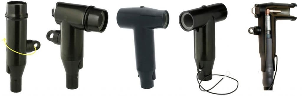
33kV T Plug Type Cable Connectors
The following information table enables the selection and outlines the possible cable connection types (T-Plugs, Coupling Insert & Screened Separable Connectors) and MV surge arresters compatible with Siemens NXPLUS C Wind switchgear 33kV/36kV.
Screened cable T-plugs, also known as separable connectors, are specified to terminate and connect 33kV power cables into Siemens NXPLUS C gas insulated switchgear – the external semi-conductive layer must be earthed normally via a cable connector.
Insulated cable T-plugs (without semi-conductive layer) are not permissible – this type of MV cable plug or connector is prone to partial discharge due to the proximity to earthed parts of the switchgear. Partial discharge destroys the MV cable connector causing an arc between phase and earth.
The connection of conventional 33kV cable sealing ends or terminations via elbow adapters is not permissible either as this type of medium voltage power system is also insulated but not screened (no external semi-conductive layer).
| Circuit-breaker Panels 630 A / 800 A 33kV/36kV | ||||||||
| Number Of Cables Per Panel & Phase | Connector Manufacturer | Rated voltage | Conductor Cross- Section sqmm | Cable Insulation | T-Plugs/Phase Bolted | Coupling Inserts/ Coupling Plugs / Bolted | Surge Arresters With Coupling Arresters/Phase | Inserts Coupling Unit |
| 1 | Nexans Euromold | 36kV | 50 to 240 | EPDM | 1x M400TB/G | – | 1x 400PB-5(10)SA-xxx | – |
| 36kV | 50 to 240 | EPDM | 1x M430TB/G | – | 1x 300SA-10-xx | – | ||
| 36kV | 50 to 630 | EPDM | 1x M484TB/G | – | 1x 800SA-10-xx | – | ||
| 36kV | 300 to 630 | EPDM | 1x M440TB/G | – | 1x 400PB-5(10)SA-xxx | – | ||
| Südkabel | 36kV | 70 to 300 | Silicone | 1x SET 36 | – | – | – | |
| 36kV | 70 to 500 | Silicone | 1x SEHT 33 | – | 1x MUT 33 | 1x KU 33 | ||
| nkt Cables | 36kV | 25 to 300 | Silicone | 1x CB 36-630 | – | 1x CSA36-10 | – | |
| 36kV | 400 to 630 | Silicone | 1x CB 36-630(1250) | – | 1x CSA36-10 | – | ||
| Tyco Electronics Raychem | 36kV | 25 to 300 | Silicone | 1x RSTI-66xx | – | 1x RSTI-CC-66SAxxx | – | |
| 36kV | 25 to 300 | Silicone | 1x RSTI-68xx | – | – | – | ||
| 36kV | 400 to 630 | Silicone | 1x RSTI-66Lxx | – | 1x RSTI-66SAxxx | 1x RSTI66CP-M16 | ||
| 36kV | 400 to 800 | Silicone | 1x RSTI-69xx | – | – | – | ||
| 2 | Nexans Euromold | 36kV | 50 to 240 | EPDM | 2x M400TB/G | 1x M400CP | – | – |
| 36kV | 50 to 240 | EPDM | 1x M430TB/G | 1x M300PBM-630A | 1x 300SA-10-xx | – | ||
| 36kV | 50 to 360 | EPDM | 1x M484TB/G | 1x M804PB/G | – | – | ||
| 36kV | 300 to 630 | EPDM | 2x M440TB/G | 1x M400CP | – | – | ||
| Südkabel | 36kV | 70 to 500 | Silicone | 2x SEHT 33 | 1x KU 33 | – | – | |
| nkt cables | 36kV | 25 to 300 | Silicone | 1x CB 36-630 | 1x CC36-630 | 1x CSA36-10 | – | |
| 36kV | 25 to 300 | Silicone | 2x CB 36-630 | 1x CP 630C | – | – | ||
| 36kV | 400 to 630 | Silicone | 2x CB 36-630(1250) | 1x CC36-630(1250) | 1x CSA36-10 | – | ||
| 36kV | 400 to 630 | Silicone | 2x CB 36-630(1250) | 1x CP 630C | – | – | ||
| Tyco Electronics Raychem | 36kV | 25 to 300 | Silicone | 1x RSTI-66xx | 1x RSTI-CC-66xx | – | – | |
| 36kV | 25 to 300 | Silicone | 1x RSTI-68xx | 1x RSTI-CC-68xx | – | – | ||
| 36kV | 400 to 630 | Silicone | 2x RSTI-66Lxx | 1x RSTI-66CP-M16 | – | – | ||
| 36kV | 400 to 800 | Silicone | 1x RSTI-69xx | 1x RSTI-CC-69xx | – | – | ||
1) Observe the actual short-circuit and current carrying capacity of the cables and sealing ends
| Disconnector Panel 630 A / 800 A, ring-main panel 630 A 33kV/36kV | ||||||||
| Number Of Cables Per Panel & Phase | Connector Manufacturer | Rated Voltage | Conductor Cross- Section sqmm | Cable Insulation | T-Plugs / Phase / Bolted | Coupling Inserts/ Coupling Plugs / Bolted | Surge Arresters With Coupling Arresters / Phase | Inserts Coupling Unit |
| 1 | Nexans Euromold | 36kV | 50 to 240 | EPDM | 1x M400TB/G | – | 1x 400PB 5(10) SA-xxx | – |
| 36kV | 50 to 240 | EPDM | 1x M430TB/G | – | 1x 300SA-10-xx | – | ||
| 36kV | 50 to 630 | EPDM | 1x M484TB/G | – | 1x 800SA-10-xx | – | ||
| 36kV | 300 to 630 | EPDM | 1x M440TB/G | – | 1x 400PB 5(10) SA-xxx | – | ||
| Südkabel | 36kV | 70 to 500 | Silicone | 1x SET 36 | – | – | – | |
| 36kV | 70 to 500 | Silicone | 1x SEHT 33 | – | 1x MUT33 | 1x KU33 | ||
| nkt Cables | 36kV | 25 to 300 | Silicone | 1x CB36-630 | – | 1x CSA36-10 | – | |
| 36kV | 400 to 630 | Silicone | 1x CB36-630(1250) | – | 1x CSA36-10 | – | ||
| Tyco Electronics Raychem | 36kV | 25 to 300 | Silicone | 1x RSTI-66xx | – | 1x RSTI-CC-66SAxxx | – | |
| 36kV | 25 to 300 | Silicone | 1x RSTI-68xx | – | – | – | ||
| 36kV | 400 to 630 | Silicone | 1x RSTI-66Lxx | – | 1x RSTI-CC-66SAxxx | 1x RSTI-66CPM16 | ||
| 36kV | 400 to 800 | Silicone | 1x RSTI-69xx | – | – | – | ||
| 2 | Nexans Euromold | 36kV | 50 to 240 | EPDM | 2x M400TB/G | 1x M400CP | – | – |
| 36kV | 50 to 240 | EPDM | 1x M430TB/G | 1x M300PB/G | – | – | ||
| 36kV | 50 to 630 | EPDM | 1x M484TBG | 1x M804PB/G | 1x 800SA-10-xx | – | ||
| 36kV | 300 to 630 | EPDM | 2x M440TB/G | 1x M400CP | – | – | ||
| Südkabel | 36kV | 70 to 500 | Silicone | 2x SEHT 33 | 1x KU33 | – | – | |
| nkt Cables | 36kV | 25 to 300 | Silicone | 1x CB36-630 | 1x CC36-630 | 1x CSA36-10 | – | |
| 36kV | 25 to 300 | Silicone | 2x CB36-630 | 1x CP-630C | 1x CSA36-10 | – | ||
| 36kV | 400 to 630 | Silicone | 1x CB36-630(1250) | 1x CC36-630(1250) | 1x CSA36-10 | – | ||
| 36kV | 400 to 630 | Silicone | 2x CB36-630(1250) | 1x CP-630C | – | – | ||
| Tyco Electronics Raychem | 36kV | 25 to 300 | Silicone | 1x RSTI-66xx | 1x RSTI-CC-66xx | 1x RSTI-CC-66SAxxx | – | |
| 36kV | 25 to 300 | Silicone | 1x RSTI-68xx | 1x RSTI-CC-68xx | – | – | ||
| 36kV | 400 to 630 | Silicone | 2x RSTI-66Lxx | 1x RSTI-66CP-M16 | 1x RSTI-CC-66SAxxx | 1x RSTI-66CPM16 | ||
| 36kV | 400 to 800 | Silicone | 1x RSTI-69xx | 1x RSTI-CC-69xx | – | – | ||
| 3 | Nexans Euromold | 36kV | 50 to 240 | EPDM | 1x M430TB/G | 1x M300PBM- 630A | – | – |
| nkt Cables | 36kV | 25 to 300 | Silicone | 1x CB36-630 | 2x CC36-630 | – | – | |
| 36kV | 2x CP-630C | – | – | |||||
| 36kV | 400 to 630 | Silicone | 1x CB 36-630(1250) | 2x CC36-630(1250) | – | – | ||
| 36kV | 400 to 630 | Silicone | 2x CB 36-630(1250) | 1x CP-630C | – | – | ||
| Tyco Electronics Raychem | 36kV | 25 to 300 | Silicone | 1x RSTI-66xx | 2x RSTI-CC-66xx | – | – | |
| 36kV | 25 to 300 | Silicone | 1x RSTI-68xx | 2x RSTI-CC-68xx | – | – | ||
| 36kV | 400 to 630 | Silicone | 3x RSTI-66Lxx | 2x RSTI-66CP-M16 | – | – | ||
| 36kV | 400 to 800 | Silicone | 1x RSTI-69xx | 2x RSTI-CC-69xx | – | – | ||
1) Observe the actual short-circuit and current carrying capacity of the cables and sealing ends
33kV Cables
Cable T-Plug Connectors
The following table outlines the screened separable connector, also referred to as cable sealing ends, suitable for 33kV/36kV cables according to IEC 60502-2 and VDE 0276-620.
The cable T-plug connection types are suitable for medium voltage bushings with outside cone as Interface C Type Bushings according to EN50181 for 33kV cables with conductor cross-section up to 800sqmm copper/aluminium.
| Cable Type 33kV/36kV | Connector Manufacturer | 33kV Cable Connector Type | Cross-Section sqmm | Comment |
| 1-core cable, PE and XLPE- insulatedN2YSY (Cu) and N2XSY (Cu) orNA2YSY (Al) and NA2XSY (Al) | Nexans Euromold | M400TB/G | 50 to 240 | EPDM with semi-conductive layer |
| M430TB/G | 50 to 240 | EPDM with semi-conductive layer | ||
| M484TB/G | 70 to 630 | EPDM with semi-conductive layer | ||
| M440 TB/G | 300 to 630 | EPDM with semi-conductive layer | ||
| nkt cables | CB 36-630 | 25 to 300 | Silicone with semi-conductive layer (optionally with metal housing) | |
| CB 36-630(1250) | 400 to 630 | Silicone with semi-conductive layer (optionally with metal housing) | ||
| Südkabel | SEHDT 33 | 70 to 500 | Silicone with semi-conductive layer (optionally with metal housing) | |
| Tyco Electronics Raychem | RSTI-66xx | 25 to 240 | Silicone with semi-conductive layer, with capacitive measuring point | |
| RSTI-68xx | 25 to 240 | Silicone with semi-conductive layer, with capacitive measuring point | ||
| RSTI-66Lxx | 400 to 630 | Silicone with semi-conductive layer, with capacitive measuring point | ||
| RSTI-69xx | 400 to 800 | Silicone with semi-conductive layer, with capacitive measuring point |

N2XSY XLPE PVC – 18/30 (36)kV Cable Connectors
33kV Surge Arresters
Surge arresters for pluggable onto cable T-plugs and are recommened for MV-HV cable and power systems:
- if the 33kV cable is directly connected to the overhead line
- if the protection zone of the 33kV surge arrester at the end tower of the overhead line does not cover the high voltage switchgear
- in offshore wind farms
| Surge Arrester 33kV/36kV | 1 Cable Per Phase | 2 Cables Per Phase | ||||
| Circuit-breaker Panel | Disconnector Panel | Ring-main Panel | Circuit-breaker Panel | Disconnector Panel | Ring-main Panel | |
| Nexans Euromold 400PB-10-SA-45L | X | X | X | – | – | – |
| Nexans Euromold 300SA-10-xx | X | X | X | X | X | X |
| Südkabel MUT 33 + KU 33 | – * | X | X | – | – | – |
| nkt Cables CSA 36-10 | X | X | X | X** | X | X |
| Tyco Electronics Raychem RSTI-CC-66SAxxx | –* | X | X | –* | X | X |
| Tyco Electronics Raychem RSTI-66SAxxx | –* | X | X | –* | X | X |
* protrudes into the floor area; possible depending on the local conditions, e.g. with sufficient hole depth
** depending on the cable plug type – contact T&D to discuss possible combinations of cable connection types and surge arresters in NXPLUS C Wind up to 36kV.
➡ View complete range of Surge Arresters 11kV 33kV MV HV
Screened separable connectors and surge arresters must be provided by the same manufacturer and used only with one cable connected per 33kV phase. Some types of surge arresters exceed the permissible dimensions as outlined in the table above.

Ellis Patents | Nexans | ABB Furse | Prysmian | Pfisterer – Distributors

Credit Nexans – contact us for HV Cable Joints, Terminations & Connectors
Credit ABB – Joint, Terminate & Connect Medium & High Voltage Cables
Thorne & Derrick
T&D are UK distributors and worldwide exporters of Cable Installation, Cable Jointing, Duct Seals, Substation & High Voltage Electrical Safety Equipment – we service UK and global businesses involved in cable installations, jointing, substation, overhead line and electrical construction at LV, 11kV, 33kV and EHV.
Since 1985, T&D have established a solid reputation based on Service, Integrity and Trust – contact us with your enquiry.
33kV Cable Terminations – Raychem Heat Shrink Terminations (VSLP9 Switchgear)
January 26th, 2018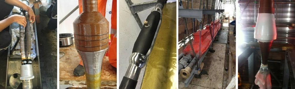
- Application: 33kV Cable Terminations – XLPE Cables Into VSLP9 Type Switchgear
- Cable Jointer: Craig Kilkenny – EHV Cable Jointer / Fitter
- Product Category: MV HV Power Cable Terminations
-
by Chris Dodds T&D - estimated reading time 5 minutes
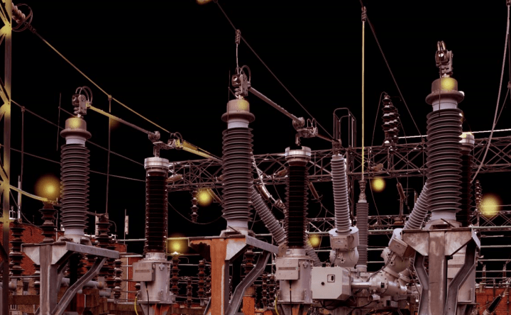
33kV Cable Terminations Installation
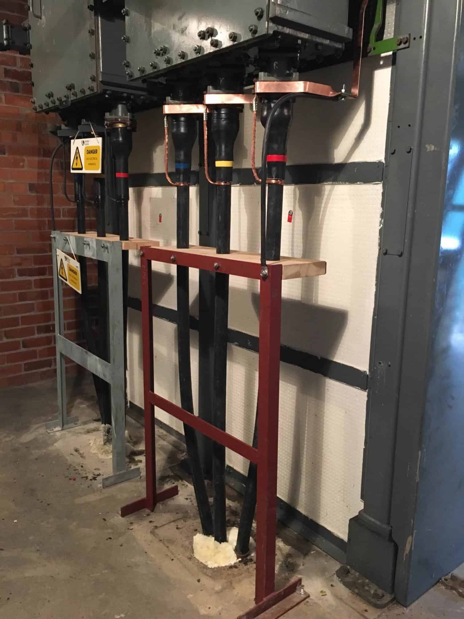
Here, high voltage substation cables are shown connected and terminated into switchgear using 33kV cable terminations.
The copper earthing tapes are used to bond all of the cable glands together which are providing mechanical retention to the 33kV high voltage power cables.
The earth tapes are clamped and attached to the substation earthing system as they are insulated from the 33kV cable box and high voltage oil-filled switchgear. The whole bank of HV switchgear is insulated from the ground and has its own earth which runs through a Current Transformer (CT) for protection reasons – the separate ‘frame earth’ is painted green in the photograph below. The stand for the cable cleats was also bonded to the substation earth. As there is a steel sandwich plate fitted to the front of the wooden cable cleats the threaded bar used is stainless steel to avoid circulating currents.
Sealing Cable Ducts 33kV
Client specified expanding foam has been used to seal the substation cable ducts within the high voltage substation – outside the substation the 33kV cable ducts were effectively sealed using a specified system to provide certain protection against water ingress and gas migration using recognised systems such as the CSD RISE duct seal or Filoform Filoseal re-enterable cable seals.
The insulating oil is usually heated before the high voltage cable box is dismantled by venting it above and heating with halogen heaters.
Stripping & Terminating 33kV Cables
The 33kV cables were stripped using the correct cable jointing tools – the PVC cable sheath was thoroughly stripped from the high voltage power cable using the Boddingtons “plough” type sheath stripper. The cable jointer then removed the XLPE insulation cleanly and without damaging the cable using Alroc LH2 tool suitable for cable stripping HV cables up to 60mm.
Finally, Alroc CWB 18-60 tool was used to remove the bonded semicon from the cable – the “blue tool” manufactured by Alroc is preferred by jointers for working on medium/high voltage power cables where a clean square cut of the semicon without jagged finish is vital to the long term reliability of power cable performance.

Poor cable jointing skills with respect to MV-HV cable preparation can create future cable failure potential – it is critical a skilled jointer uses the correct cable tools to prepare MV-HV cables before installing joints, terminations or connectors up to 33kV.
Comments from fellow HV cable jointers:
Jimmy Nicklin: “Nice job Craig Kilkenny. I did a nine bank of these 15 years ago and is quite the breakdown and remake to do.”
Dean Wilson: “Nice neat work Craig Kilkenny and yes I agree Jimmy Nicklin it’s getting the old oil out that’s a job in itself!”
Andrew Brezovszky: “Very neat 33kV cable terminations !”
Thorne & Derrick International
Should you require any assistance with the selection or specification of heat shrink terminations to suit 33kV high voltage power cables please do not hesitate to contatct us.
T&D distribute the most extensive range of MV & HV Cable Joints & Terminations, Cable Installation Accessories & Cable Pulling Equipment – we service UK and international clients working on underground cables, overhead lines, substation earthing and electrical construction at LV, 11kV, 33kV and EHV transmission and distribution voltages.
- Key Products: MV-HV Cable Joints & Terminations, Cable Cleats, Duct Seals, Cable Transits, Underground Cable Protection, Cable Spikers, Cable Jointing Tools, Feeder Pillars, Cable Ducting, Earth Tapes, Electrical Safety, Cable Glands, Arc Flash Protection & Fusegear.
- Distributors for: 3M, ABB, Alroc, Band-It, Catu, Cembre, Centriforce, CMP, Elastimold, Ellis Patents, Emtelle, Furse, Lucy Zodion, Nexans Euromold, Pfisterer, Polypipe, Prysmian, Roxtec.

LV – Low Voltage Cable Joints, Glands, Cleats, Lugs & Accessories (1000 Volts)

MV HV – Medium & High Voltage Cable Joints, Terminations & Connectors (11kV 33kV EHV)

Cable Laying – Underground Cable Covers, Ducting, Seals & Cable Pulling Equipment
More…
T&D’s Power Blog covers: LV MV HV & EHV Transmission & Distribution, Substations, Switchgear, Cable Jointing & Termination, Cable Fault & Repair, Underground Cables.
➡ Visit Power Blog.

