

Blog
Thorne & Derrick Announce Distribution Agreement & Contract With Nexans
January 10th, 2018
MV HV | Shearbolt Connectors | Cabinets | Joints | Terminations | Connectors Up to 66kV
Press Release by Chris Dodds - T&D Sales & Marketing Manager
January 10, 2018
Thorne & Derrick have signed an International Distribution Agreement with Nexans Power Accessories UK.
Thorne & Derrick, based in the UK, are national distributors of LV, MV & HV Cable Installation, Jointing, Substation & Electrical Equipment – servicing businesses involved in cable installations, jointing, substation, overhead line and electrical construction at LV, 11kV, 33kV, 66kV and EHV.
Signing the new Nexans Power Accessories UK, International Distribution Agreement, is a key part of Thorne & Derrick’s growth strategy for the next 5 years.
With T&D’s knowledge and experience for promoting and selling Medium & High Voltage Cable Accessories this new partnership with Nexans delivers the most complete range of Joints, Terminations and Connectors for medium voltage power systems.
Our new partnership unites our commitment to providing safe and reliable MV-HV Cable Accessories meeting International Standards up to 66kV:
- Slip-On, Cold Shrink & Heat Shrink Joints & Terminations
- Separable Connectors – Interface Bushings A to F
- Cable Jointing Tools – Medium & High Voltage MV HV
- Switchgear & Transformer Bushings
- Cable Jointing Training & Competency Certification
- See Products from Nexans Euromold
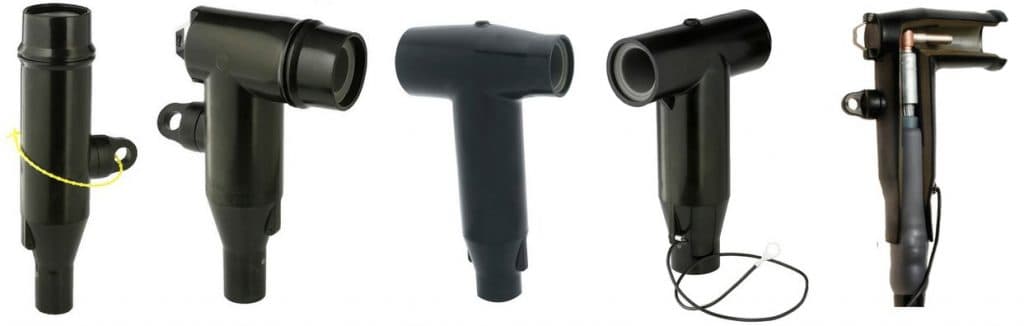
Seperable Connectors | Cable Joints | Cable Terminations | MV HV 11kV 33kV 66kV

Stock, Service & Expertise
T&D project experience has enabled us to build a solid reputation for the reliable supply of leading brands across our core product groups. Complementing our UK Sales Offices, we have a multi-million pound stock capacity with the addition of our new Southern warehouse and can supply many products typically by next day delivery.
Thorne & Derrick’s Sales & Marketing Manager Chris Dodds commented, “T&D are committed to a successful business partnership with Nexans and with agreed business plan in place to support this new agreement we expect a record-breaking 2018. Our Sales Team look forward to consolidating existing and developing new business for Nexans. The contract agreement further establishes T&D’s position in the UK market as MV-HV Specialist Electrical Distributors. We enjoyed record onboarding of new customers in 2017 and now have a cooperative sales and marketing campaign to implement with Nexans. We look forward to meeting and discussing this exciting development with our clients.”
Jonny Hewitt UK Power Team Leader with T&D added, “working with the UK DNO’s and their preferred ICP’s we look forward to developing existing relationships and presenting the full portfolio of Nexans MV Products available from T&D up to 66kV to new clients. We will be working closely with Nexans and contractors to achieve the specification and supply of their broad range of joints, terminations and connectors for 11kV, 33kV and 66kV electricity networks.”
Pictured: Left to Right At our new North East office, Jonny Hewitt, Jeff Jhanke, David Tinning, Chris Dodds, Martin Wigham from Thorne & Derrick with Josh Doust and Alasdair Cook (Business Development Managers with Nexans).

Richard Derrick
Thorne & Derrick’s Managing Director Richard Derrick comments, “the commercial and technical support of Nexans is excellent and their market-leading approach to the development and innovation of Medium Voltage Cable Accessories is unsurpassed. This presents an excellent business growth opportunity for T&D. Likewise, with the track-record of our company and strong position in the industry we can deliver new business for Nexans.”
➡ Update
Nexans Power Accessories Achieve Success With Thorne & Derrick

Pictured: Richard Derrick with Josh, Chris and Alasdair following the official Distribution Contract handover.
Learn more about T&D, The MV HV Electrical Distributors.
♦ Category: HV Joints Terminations Connectors 11kV 33kV 66kV

Pfisterer – Stockist & Distributor

Inner Cone Plugs
Offshore Cable Joints
January 9th, 2018
Cable Joints For British Standard, IEC & NEK606 Standard Offshore Cables
Uploaded By: Chris Dodds - Thorne & Derrick Sales & Marketing Manager
Thorne & Derrick International, based in the UK, distribute an extensive range of Offshore Cable Joints to suit halogen free (zero halogen), flame retardant, MUD resistant, heat resistant and fire resistant offshore and shipboard power, control and instrumentation cables.
Contact T&D to discuss offshore cable jointing and splicing applications in the oil and gas industry – joints are available for NEK606 (RFOU BFOU EPR TCWB) and BS6883/BS7917 (UKOOA) Cables.
NEK606 cable joints can be supplied to connect and repair flame retardant, fire, oil and MUD resistant cables.
Cable joints are also available for leading manufacturers cables including Nexans AmerCable (Gexol), General Cable, Okonite, Helkama Bica Oy, Nexans and Prysmian.
Specialist offshore cable joints are also available to suit Marine and Offshore Cables (IEC 60092) – this includes heat shrink cable joints utilising zero halogen tubings for flame-retardant (IEC 60332-3A) and fire-resistant (IEC 60331) cables.
Typical application and installations include FPO, FPSO, Drilling Ship, Topside and FSU – especially where cable joints are required to maintain circuit integrity and continue to work for a specified period of time under defined fire conditions.
- Cold Shrink Cable Joints – suitable for potentially explosives atmospheres where no “hot-working” or naked flames are permitted
- Heat Shrink Cable Joints – suitable for where “hot-working” is permitted
- Resin Cast Hydrocarbon Resistant Cable Joints – providing excellent resistance to aggressive and corrosive oil/chemicals/gases in hazardous areas
In accordance with American Bureau of Shipping (ABS), Lloyds Register of Shipping (LR), Canadian Standards Association (CSA), Transport Canada Marine Safety, Det Norske Veritas (DNV), Underwriters Laboratories Inc. (UL), Intertek Testing Services (ETL) and United States Coast Guard (USCG).
Thorne & Derrick stock the most complete range of 3M Cable Joints for offshore jointing and repairing of EPR insulated flexible wire braided low voltage power cables.

Cable Joints LV Low Voltage | Cold Shrink | Heat Shrink | Resin for Offshore Cables
3M Scotchcast Offshore Cable Joints
The 3M LVI3 range of Scotchcast Cable Joints utilising 3M 1402FR Resin are extensively specified for the jointing, splicing and repair of offshore cables in the oil and gas industry up to 3.3kV – this includes low voltage power, control and instrumentation cables installed in Zone 1 & Zone 2 hazardous areas designated according to ATEX Directive.
For medium/high voltage power cables there is a choice. MV- HV Cold Shrink joints are available with cold shrink outer protection jacket or encapsulated with a cable joint shell and filled with Scotchcast 1402FR resin to provide additional protection against aggressive and corrosive chemicals, oils, gases and MUD.
Extreme Temperatures
3M LVI3 cable joint kits should be installed in temperatures above freezing point to ensure that the Scotchcast resin is properly mixed and cured (the resin can be warmed by the cable jointer in a vehicle if required). Once installed the cable joints are stable at lower temperatures down to -40°C.
High Voltage Joints
Thorne & Derrick have produced custom specification offshore 33kV cable joints to repair and connect submarine power cables for land underground installation – typically the straight joints would be installed on the cable deck of an Offshore Substation (OSS) located on an offshore wind farm.
The cable test requirements were in accordance with IEC 60502-4, rated or operating voltage 19kV/33kV and maximum voltage 33kV – briefly the 33kV offshore cable specification would include XLPE insulation, extruded bonded semi conductive compound, water blocking tapes, metallic screen and a single layer of galvanised steel wire armours filled with bitumen.
Contact T&D for offshore repair joints in a range of materials for LV MV HV cables including heat shrink, cold shrink or resin cable joints.
♦ View our complete range of Offshore Cables, Cable Accessories (Joints | Glands | Cleats) & Electrical Equipment for use with IEC Cables.


3M LVI3 Offshore Cable Joints | Power | Control | Instrumentation Cables
See also: Offshore Marine Cables – NEK 606 BFOU RFOU Prysmian Draka Cables
Sealing Cable Ducts Containing Multiple Single Core Cables In A Data Centre
January 8th, 2018
Sealing Cable Ducts
- Guest Blog: Steve Groocock (Duct Seal Products – Account Manager at Filoform UK)
- Product Category: Cable Duct Sealing
Filoform FiloSeal +HD is a duct sealing system specified to protect and seal larger heavy armoured power and high voltage cables in LV, MV & HV substation ducts, bore holes or transit frames – the duct seal provides a strong support and cable sealing system using hexagonal tubes building a re-enterable honeycomb structure to resist water, gas and fire.
Re-enterable cable duct seals are easy to apply regardless of the type of cable scenario in the cable ducts as it uses a strong but flexible hexagonal tube structure to support the cable and provide a strong backing for the cable seal.
The duct seal system provides waterproof and gastight sealing of LV-HV and 11kV-33kV power cables into ducts. The FiloSeal+HD is suitable for any cable configuration (single, trefoil cables or multiple cables) contained within one duct and also allows for easy re-entry of the duct seal to add or remove cables or pipes as required.
Filoform Filoseal+HD is covered by a Test Report documenting successful pass status at Nedlab Laboratory for the following – this is based upon using Filoform’s hexagonal support system and sealing cable using their MD+ sealant.
- Pressure Test, Bending Test & Pull Strength
- Resistance Test Against Chlorine, Methane Gas & Chemicals In Hazardous Areas
- Resistance Test Against Hydrogen Sulphide Gas
- Resistance To Onshore & Offshore Hydrocarbons

FiloSeal+HD Cable Duct Seals – Honeycomb Structure
Duct Sealing
Installing & Preparing The Cable Seal
Steve Groocock is the Duct Seal Product Manager at Filoform. Below he explains about attending a data centre site where he provided installer training prior to the installation of Filoseal +HD Re-enterable Duct Seal System.
“A skill is something that is learned over a period of time but sometimes it is best to pass along experience to a new user of any equipment, this includes cable duct seals. Recently, I attended site for a company who were working on the LV cabling associated with a new build data centre into an existing building structure.
The LV cable, ducting and electrical distribution system utilised existing switch rooms where possible but in order to add capacity to these areas, new penetration holes for the cabling needed to be added. These holes were core drilled directly through the existing structure. Once the cables had been pulled, there remained clear passages for the ingress of moisture, gas, dust and rodents into cable ducts.
Taking the strips of adjoined hex tubes, insert them around and between the cables to be sealed ensuring the spacing required is maintained – the strips can be inserted as a flat line or rolled to form a tight group of 5. If space is not available, the strip of hex tubes may be torn down to individual hex tubes.
Start at the bottom of the cable duct with the large blue tubes and build up to completion. Should there be heavy cables in the ducts, such as 11kV/33kV high voltage power cables, the hex tubes can be nested i.e. one small tube placed inside the other larger tube. The small light blue hex tubes are used to fill and seal the remaining small gaps in the cable duct. The installer should ensure the tubes are packed tightly to prevent cable movement.
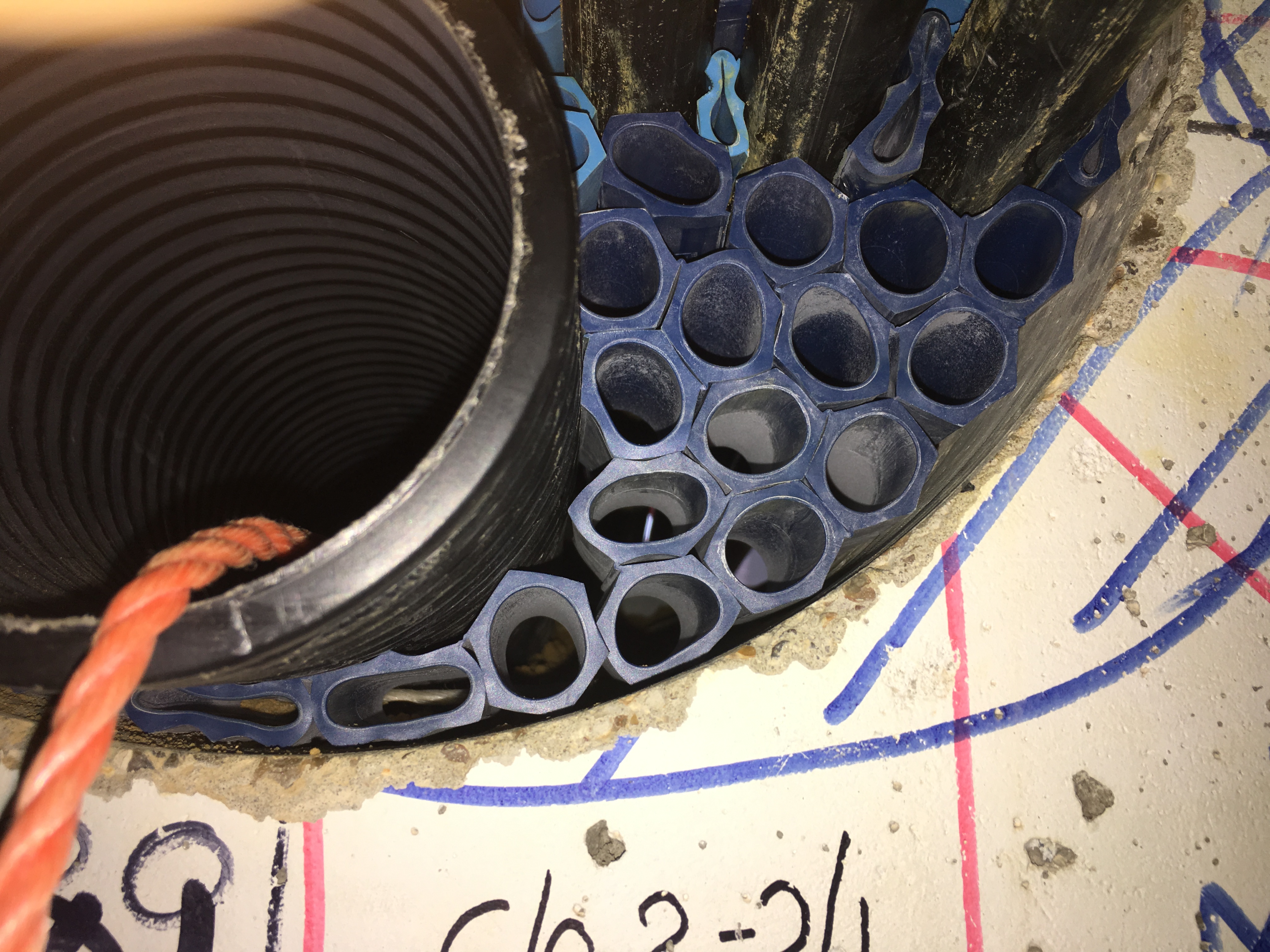
Filoseal+HD duct sealing kits have been tested to provide watertight, gastight and/or fire resistant cable seals and were thus specified to fill in the voids in the concrete core drilled holes at the data centre.
Training took two hours and in this time it was up to me to pass on as much experience as possible at a steady pace so the new installer could take it understand and adopt the knowledge. The installer had previously not seen a duct sealing system like this so I took time to familiarise them with the component parts and how a finished cable duct seal installation should look like by way of a sample in a clear duct replica. I also showed the excellent Filoform HD installation video which can be viewed below.
Once we had seen the video and experienced the component parts of the duct seal we started to seal one side of one cable duct. The customer will be sealing both sides of the cable duct wall – we can see this in the pictures upon insistence from their end client.

The hands on training starts with myself and the trainee cleaning and abrading the cables and cable duct for the first 20-25mm inside the hole in the wall – cleaning cloth is provided with the duct seal kit. Preparation is key to the whole system – the most important point I stressed to achieve a hexagonal backing piece between each and every cable to create a reliable water and gastight cable duct seal.

The hexagonal tubes are placed around the cables to be sealed filling up all the gaps using the large and small hexagonal backers to ensure the cable support system is compact and tight resembling a honeycomb structure.
This is explained in the Video and instructions supplied with the duct seal kit but until seen it is not necessarily clear as to why. The space is there to ensure the duct sealant component, called Filoseal MD+, can reach all the areas of the void or cable duct needed to be sealed. This site was particularly challenging as the low voltage cables were held down close and clamped to the work face by cable cleats. However, I moved to the other side of the wall and moved the cables in a pit until my trainee could get the hexagonal pieces between each and every cable and between the cables and the core drilled hole edge.
Here the cables are pictured clamped to the cable channel using trefoil cable cleats as the cables depart the duct which was sealed using Fioloseal type duct sealing mastics.
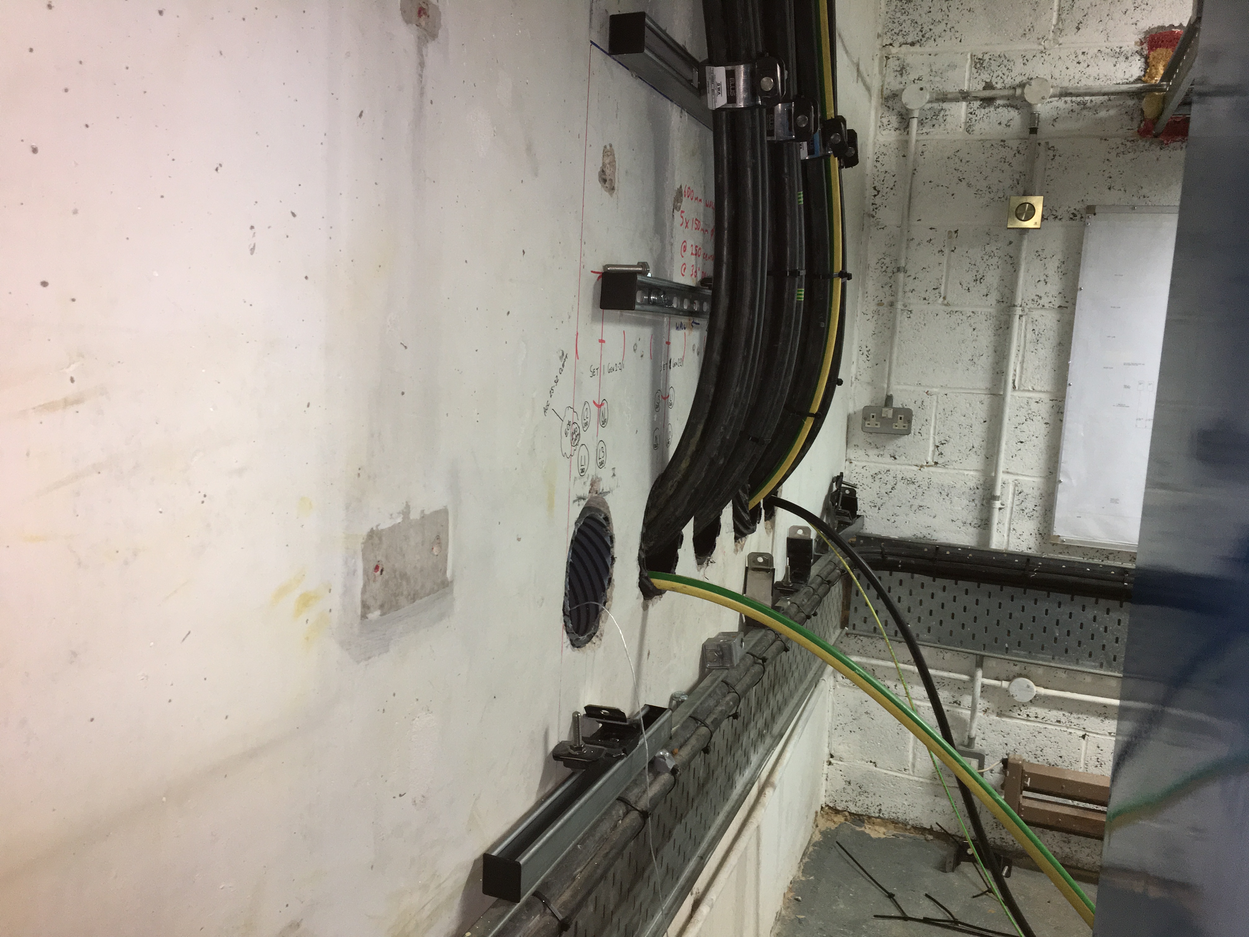
This is the end of stage one. Once we both looked and examined the backing ensuring there were gaps around the cables to be sealed as specified, we moved on to the addition of the sealing mastic. The cable sealing mastic can be applied using a standard mastic gun, however we recommend investment in a quality installation gun. Once the sealant mastic is loaded in the gun I demonstrated on the lower half of this cable install how to ensure a cable seal by running a good bead around the hole edge on every cable. Once we had gone through several tubes of mastic we brought out the finishing sponge to wipe down and tidy the mastic finish – the duct sealant can take from 4 to 20 days to fully cure depending on local ambient temperatures and air humidity levels. Typically in the UK curing takes 8-20 days and backfilling of the installation should be avoided until at least 10 days after installation.
When backfilling ensure adequate packing is below the sealed cables in the duct before adding materials above the cables. In a vertical cable duct, group together strips or rolled groups of tubes and squeeze them into the a duct as one single unit.
Then proceed to maintain the required cable spacing by adding either large or small tubes (groups of or singly).

Duct Sealing – Preparation Is Key
The mastic should be patted in and around every cable ensuring each and every part of the cable duct seal was treated the same way – this patting motion encourages the cable sealant mastic to adhere to the hexagonal backing. Final checks led me to further pat parts between cables using the sponge edge.”
Cable Duct Seal Selection Table
| Filoform Ref | Cable Duct Seal Description | Max Cable Duct Diameter (mm) | Order Unit |
|---|---|---|---|
| 280010 | FiloSeal+HD – 75mm > 110mm | Ø 110 max. | per piece |
| 280020 | FiloSeal+HD – 125mm > 160mm | Ø 160 max. | per piece |
| 280030 | FiloSeal+HD – 180mm | Ø 180 max. | per piece |
| 280040 | FiloSeal+HD – 200mm | Ø 200 max. | per piece |
| 280050 | FiloSeal+HD – 225mm | Ø 225 max. | per piece |
| 280060 | FiloSeal+HD – 250mm | Ø 250 max. | per piece |


Duct seals suitable for LV-HV power cables in single, trefoil or multiple configurations, including 11kV Triplex and 33kV high voltages

Provides advanced and assured sealing against water and gas for cable ducts, bore holes and openings
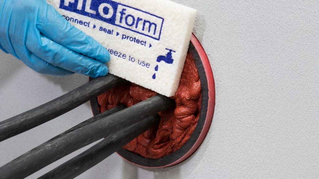
Re-enterable sealing system future-proofed for retrofit of new cables or re-routing of existing through cable ducting
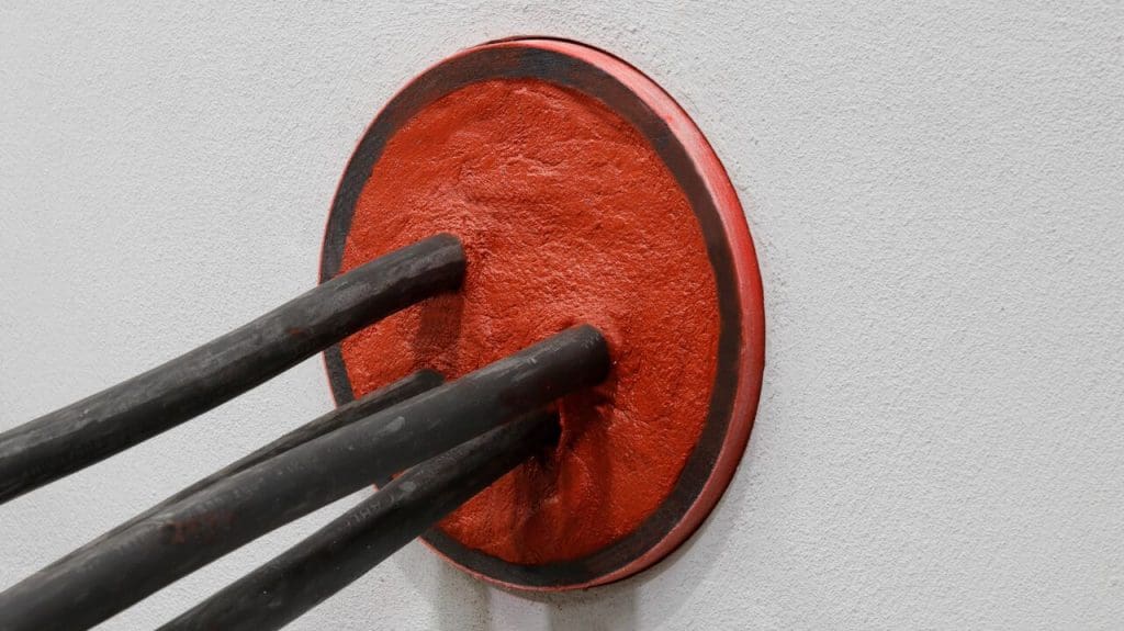
Cable duct seals provide protection of substations and basements against flood, fire and gas ingress dangers
Conclusion
Filoseal+HD duct seal system using MD+ has been heavily tested against pressure, pulling forces, chemicals, gases and hydrocarbons for use with low, medium and high voltage cables. Below we can summarise the results from Nedlab Laboratory Test Reports.
| Duct Seal Test Description | Measurement | Result | Pass or Fail |
| Pressure | 2.0 Bar | 1.0 Bar long term, 2 Bar short term | PASSED |
| Pulling Force | 100Kg | 100Kg – 1000 Newtons | PASSED |
| Bend Test | 10xd at 45 Degrees | 10xd at 45 Degrees, with 1 Bar pressure | PASSED |
| Chlorine Gas | 100% for 7 Days | Slight change on colour and texture | PASSED |
| Methane Gas | 100% for 7 Days | Slight change on colour and texture | PASSED |
| Diesel | 100% for 2 Years | Hardly any change | PASSED |
| Petrol / Benzene | 100% for 2 Years | Hardly any change | PASSED |
| Ethanol | 100% for 42 Days | Hardly any change | PASSED |
| AD Blue | 100% for 21 Days | No change | PASSED |
| ASTM Oil | 100% for 2 Years | Hardly any change | PASSED |
| Hydrogen Sulphide (H2S) | 200ppm for 5 Days | Hardly any change | PASSED |

Final Pressure Test – after completion of the bending and pull strength test the cable duct seals are tested at a pressure of 2.0 Bars.
Note the Test Results documented above have been done in accordance with Filoform installation instructions, however values achieved in field installations can vary if the instructions are not followed and results may vary depending on cable and duct tolerances such as cable duct size, material and cable density volume.
Further reading:
- Trefoil Cables – Sealing Ducts & Cleating Trefoil Cables Up To 33kV
- Sealing Cable Ducts In Hazardous Areas According To ATEX Directive
THORNE & DERRICK are national distributors LV, MV & HV Cable Installation, Jointing, Substation & Electrical Equipment – we service UK and global businesses involved in cable installations, duct sealing, cable jointing, substation, overhead line and electrical construction at LV, 11kV, 33kV and EHV.
Since 1985, T&D have established an international reputation based on SERVICE | INTEGRITY | TRUST.
Contact us for 3M Electrical, ABB, Alroc, AN Wallis, CATU Electrical, Cembre, Centriforce, CMP, CSD, Elastimold, Ellis Patents, Emtelle, Euromold, Filoform , Furse, Lucy Electric & Zodion, Nexans, Pfisterer, Polypipe, Prysmian, Roxtec, Sicame, WT Henley. Invitation: Thorne & Derrick invite you to join LinkedIn’s largest LV-HV Electrical Discussion Group : Low & High Voltage Power, Cabling, Jointing & Electricals. Discussion subjects include cable installations, cable jointing, substation, overhead line and electrical construction at LV, 11kV, 33kV and EHV. Network, engage and promote your profile, company or products with over 10,000 influencers.

33kV Heat Shrink Cable Joints Connecting XLPE Cable In Underground Trench
January 8th, 2018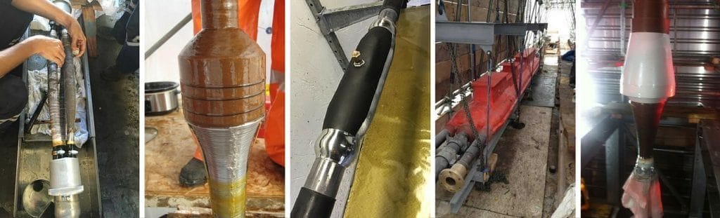
- Application: Connecting XLPE Insulated High Voltage Cable In Underground Trench
- Cable Joint Type: 33kV Cable Joints (Heat Shrink)
- Cable Jointer: Garry Hardaker Electrician & HV Jointer (Offshore)
-
by Chris Dodds T&D - estimated reading time 5 minutes
33kV Heat Shrink Cable Joints
Protecting High Voltage Cables From Water Damage
33kV heat shrink cable joints are high voltage cable jointing kits complete with mechanical connectors or compression crimp connectors for cable jointing of polymeric (XLPE) insulated cables.
Polymeric insulated cables distributing high voltage electricity at 33kV can be used to joint cables with XLPE or EPR type insulation, armoured/unarmoured and with copper wire screen (BS7870) or copper tape screened cables (BS6622).
Heat shrink cable joints feature integrated stress control sleeves and torque controlled mechanical shearbolt connectors can be used to connect conductors (copper or aluminium) without resort to use of crimping tools or associated die sets.
Mechanical cable connectors are ideal for confined space cable jointing where there is restricted working space in manholes, cable vaults and underground trenches, especially on large cross sectional area conductors where hydraulic crimping heads coupled with foot pumps are required for conductor jointing. Bolted cable connections, such as Pfisterer SICON connectors, are installed directly onto the 33kV conductor using standard Allen keys. The bolt shears off smoothly and cleanly when tightened by the cable jointer.
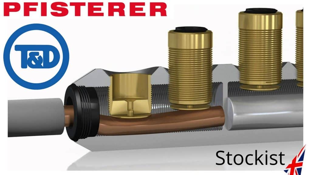
Pfisterer Sicon – cable lugs and connectors with stepless shearbolts for use with cable joints and terminations on high voltage power cable systems
Heat Shrink
Primarily, a heat shrink cable joint provides electrical insulation, mechanical protection and stress control for high voltage power cables – integral also to the cable joint design is the requirement to prevent water ingress into the cables. Although initial risk assessments would include consideration of electrical water damage, such as cable flood damage, the requirement to deliver medium/high voltage power can necessitate cable exposure to potential flooding, condensation and water immersion. A robust cable joint is designed to withstand the deteriorative effects of water in both indoor or outdoor environments.
The cable joint kits include thick-wall heat shrink adhesive lined tubes to provide high performance water sealing, protection and corrosion resistance in above ground exposed or direct buried underground cable trenches – the outer protection heat shrink tubing (colour black) provides a moisture barrier to water ingress through the activation of an inner lining of adhesive which melts and flows upon the application of a heat source provided by the cable jointers gas torch.
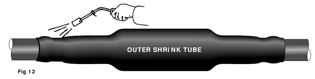
Prior to installing the outer shrink tube the jointer should clean, de-grease and abrade the outer cable sheath of the 33kV cable – to achieve an even wall thickness the cable jointer should keep the flame moving and avoid scorch or burn damage to the heat shrink or cable.
The jointer will apply heat evenly to the centre of the cable joint – once the heat shrink tube is fully recovered (“shrunk”) the joint should be smooth, wrinkle-free and the heat activated sealant should be visible at the tube ends in contact with the cable sheath.
The tough and durable heat shrink provides reinstatement of cable sheath or jacket insulation and withstands trench backfill prior to energisation of the HV joint.
The 33kV joints are installed using normal procedures for heat shrink cable joints with clear installation instructions confirming precise cable stripping dimensions and marking measurements for sheath, semicon and insulation removal – joints are installed using the standard cable jointing tools depending upon cable construction.
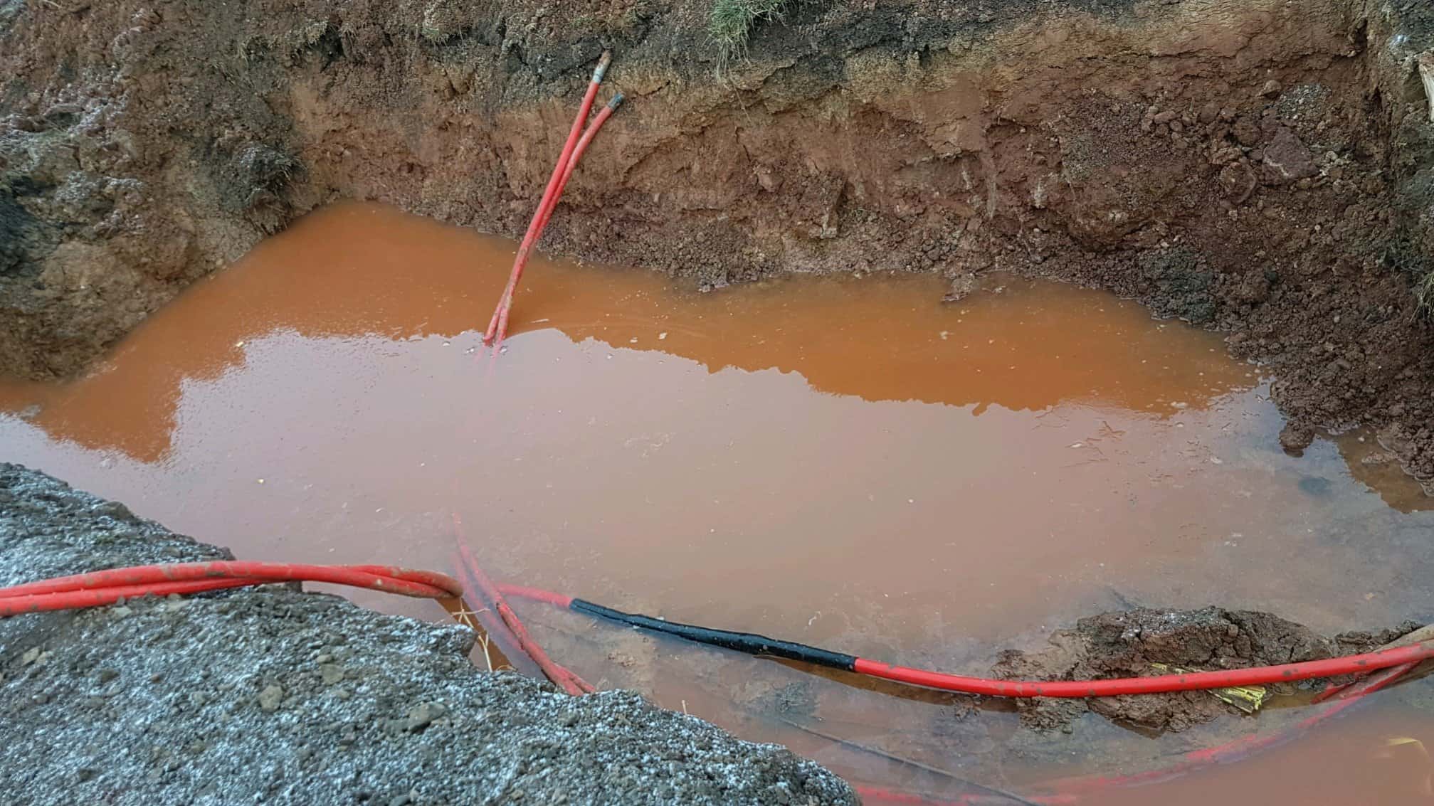
Although not designed to be permanently submerged in water, 33kV cable joints use heat shrink tubes to prevent water ingress into high voltage cables whether buried underground or located onto cable containment in MV-HV substations.

Should you require any assistance with the selection or specification of MV-HV joints or terminations please do not hesitate to contact us.
Further reading:
- Dangers Of Substandard Heat Shrink Cable Terminations On High Voltage Systems
- HV Cable Terminations – A Report Into 11kV Heat Shrink Termination Failure
Jointing 33kV Cables Using Heat Shrink Joints
The following Training Video shows the installation process for installing heat shrink joints to single core 33kV cable – this Video is for familiarisation purposes and not intended as a substitute for attending recognised industry training courses and achieving manufacturers competency. The Video produced by SPS with narration provides comprehensive guidance from the initial stripping and removal of the 33kV cable sheath to the final completion of the heat shrink joint.

More 33kV Products For High Voltage Cables ♦ 33kV Surge Arresters ♦ 33kV Fuses ♦ 33kV Lugs ♦ 33kV Portable Earthing ♦ 33kV Cable Terminations
Thorne & Derrick Specialist Electrical Distributor
LV ♦ MV ♦ HV
T&D distribute the most extensive range of LV, MV & HV Cable Jointing, Terminating, Installation & Cable Pulling Equipment – we service UK and international clients working on underground cables, overhead lines, substation earthing and electrical construction at LV, 11kV, 33kV and EHV transmission and distribution voltages.
- Key Products: MV-HV Cable Joints & Terminations, Cable Cleats, Duct Seals, Cable Transits, Underground Cable Protection, Cable Jointing Tools, Feeder Pillars, Cable Ducting, Earthing & Lightning Protection, Electrical Safety, Cable Glands, Arc Flash Protection & Fusegear.
- Distributors for: 3M, ABB, Alroc, Band-It, Catu, Cembre, Centriforce, CMP, Elastimold, Ellis Patents, Emtelle, Furse, Lucy Zodion, Nexans Euromold, Pfisterer, Polypipe, Prysmian, Roxtec.

LV – Low Voltage Cable Joints, Glands, Cleats, Lugs & Accessories (1000 Volts)

MV HV – Medium & High Voltage Cable Joints, Terminations & Connectors (11kV 33kV EHV)

Cable Laying – Underground Cable Covers, Ducting, Seals & Cable Pulling Equipment
More…
T&D’s Power Blog covers: LV MV HV & EHV Transmission & Distribution, Substations, Switchgear, Cable Jointing & Termination, Cable Fault & Repair, Underground Cables
➡ Visit Power Blog.

Dangers Of Substandard Heat Shrink Cable Terminations On High Voltage Systems
January 2nd, 2018-
Uploaded By: Chris Dodds – T&D Distributors of LV, MV & HV Cable Terminations & Cable Joints
The following LinkedIn Comments provide some expert guidance, insight and advice on how to avoid the dangers of substandard installation of heat shrink cable terminations on high voltage systems. Generally, when categorising voltages we include 11kV and 33kV power systems into the high voltage (HV) definition.
However contractors, manufacturers and the industry would also argue that 11/33kV should be classified as medium voltage (MV) and HV commences at 66kV.
The Comments below were in response to the following site installation photograph of an 11kV cable termination. Let us know your thoughts and we will include to the thread in order to improve readers knowledge and reduce industry risk.

Scott Wilkie HV Power Distribution Engineer at Scottish Power – cable entry points through the cable gland plate would be better if centralised. Crossing cores with increased stress over insulation, clearly used to phase out the cable sections in the box. Would prefer to see 11kV single cores with a trifurcating joint outside of the cable box if that was possible.
♦ See: Cable Glands MV HV
Brendan Preece, P.E. HV Electrical Engineer – in addition to previous comment, use a high voltage two-hole compression lug that matches the two-hole terminal pad for good low-resistance metal-to-metal surface area contact.
♦ See: Cable Lugs & Connectors 11kV 33kV
Tony Haggis Director at Tony Haggis Consulting Ltd – the HV cable box is designed for single core cable terminations only. It’s impossible to use 3 core cable and maintain clearances between the cores – hence the black discharge marks. Not sure why anyone would use 3 core XLPE cable these days – single core triplex is cheaper and much easier to joint and terminate. Most UK DNOs and European utilities use it. There is no way to recover the heat shrink cable terminations other than cut all the cables out and replace with single cores with trifurcating joints outside. Also I’m amused by the use of the outdoor rainsheds – not only unnecessary but they also make the clearances worse.
♦ See: Cable Boxes HV High Voltage & Terminating 11kV Triplex Cables
Colin Woodman Team Leader & HV Cable Jointer DELPRO – I could be wrong but looking at it I am struggling to see where, other than down near the bottom of the heat shrink cable terminations, that the semi con screen had been cut and the mastic installed…cables must only cross where the semi con is still in tact. This is why HV cable terminations like this should be designed from the top down not from the cable strip up.
♦ See: Cable Jointing Tools
Tony Haggis Director at Tony Haggis Consulting Ltd – in view of Colin Woodman’s comment I’ve looked a bit closer at the picture and it could be salvaged by remaking the heat shrink termination using what we used to call a “crossed core” kit that we used to use with 11kV belted paper cable. This kit included heat shrink semicon heat shrink tubes that we used to screen the cores up to the stress control tube which was placed up near the cable lug.
Perhaps stripping off the existing cable termination and extending the core screen with semicon tubes could then place the stress control tubes up between the perspex phase barriers. I personally wouldn’t guarantee it as we don’t know what discharge damage has already been caused. If one was determined to use 3 core 11kV cable in this box then a top down screen off measurement would work but I would want the termination manufacturer’s view first. Looks like the semicon has been terminated taking a measurement from the crutch leaving unscreened core in the areas to be crossed.
I’ve always advocated taking the screen-off measurement from the HV cable lug thus leaving maximum screened core in the box. However, most termination manufacturers give a bottom up dimension but will give a top down dimension when asked.
♦ See: MV HV Cables 11kV 33kV
Michael White CEO at Campbell White – Colin you are spot on where a cross or a roll on end termination you must know creepage distance on these lineal stress terminations: on all Raychem terminations 90mm from top of black semiconductor heat shrink to open conductor then you can roll and cross on the semicon screen and have no trouble. There is no science taught these days on stresses and zero potential for cable jointers. I can understand third world jointers making mistakes but not educated ones.
♦ See: Cable Jointer Training Courses
Dan James MIET Technical Services Engineer – Senior Authorised Person at NG Bailey – complete mess. As suggested above this can’t be saved. Cut it all back, do a cable joint to single cores, get rid of them heat shrink sheds and perspex.
Richard Poulter SPS Managing Director – looks like a 33kV termination because of the phase barriers but more so the sheds per phase and the length of the stress control tubes which you can see the outline of below the anti-track tubes (they look about 260mm long). You can make out the semi-conductive screen ends because of the small bulge where the yellow stress tape is applied but most of the stress control tubes are fitted below this point rather than above it. So the majority of the stress tube is not doing anything.
I suspect the heat shrink cable terminations are fitted this low because the cable jointer was probably trying to achieve a distance of 250mm from the top of the stress tubes to the bottom of the lug barrels. The cable end termination box just does not look big enough for this voltage class termination, probably better to have used single core cable and they might have had a chance of achieving the cable spacings. Lots of discharge going on. That phase on the right looks like totally different anti-track but the intense heat has discoloured the other phases by the looks of things. Has it blown yet?
Maybe do a Trif joint below the cable box and take single cores in. If little space, use Raychem IXSU heat shrink kits or a cold shrink termination. Life expectancy is hard to pinpoint but there is a lot of discharge going on so they should schedule this within a week otherwise the damage will be a lot more. The temperature at the discharge can be as high as 1000 degC and once the carbon deposit increases on the cores, the quicker it will fail.
Andy O’Malley Allteck IBEW 258 EHV Cable Jointer/Splicer – they could have broke this 3 core cable into single cores outside of the 11kV box utilising jacket reintroduction kits and glanded the single cores individually and this would of been a perfect installation.
John Thompson High Voltage Cable Splicer – Okay, honestly it looks like hell. But let’s pick this apart. There are 12 cables in this picture (4 per phase). The 11kV terminations appear to be in some kind of a protected cabinet so they could operate for a length of time if this was some form of a temporary hookup. In my opinion this is more of an engineering catastrophe than a cable splicers mishap.
Joe Kinnane HV Electrician/ Transmission Cable Jointer With Western Power – they clearly needed to be “broke out” way lower than they have been with longer spaces between the stress point on the different phases! Heat shrink tubes weren’t pushed down fully on the breakout either.



Evan Paul Galleozzie Approved Electrician – bad design of the entry of the 11kV cables which has resulted in a mess of the cable terminations. And a few of the the cables look in a poor condition. And the CPC’s could have been installed properly using crimping tools, too much copper showing. Bad, bad, bad.
Christopher Williams Head of Services and Support at IPEC Ltd – looks like a severe case of surface tracking on the heat shrink cable terminations (a form of partial discharge). This is likely caused by the inadequate installation of the feeder cables increasing the electrical stress across the surface of the high voltage cable insulation. Any dirt/dust/contamination would then have helped create small electrical discharges across the insulation causing the carbonisation you see in the image. Over time this will compromise the insulation further, finally resulting in a catastrophic failure. Interestingly, this could have been detected via PD monitoring, in this case, ultrasonic emission would have been emitted and sensors could have detected the inception and location of this defect long before it got to this stage!!!
Thorne & Derrick
Suppliers of HV Joints, Terminations & Connectors
Thorne & Derrick distribute the most extensive range of MV HV Medium & High Voltage Cable Joints, Terminations & Connectors from manufacturers including 3M, Prysmian, Nexans Euromold, Elastimold, Pfisterer CONNEX and Shrink Polymer Systems.
Heat shrink, cold shrink, push-on and slip-over cable accessories enable the jointing, terminating and connection of 11kV-33kV and 66kV-132kV cables to oil, air or gas insulated switchgear, transformers, motors and overhead lines distributing electricity at MV HV.
Thorne & Derrick stock 11kV 33kV 66kV Joints & Terminations suitable for XLPE, PILC and EPR cables, in both heat shrink and Cold Shrink technologies, to service the medium/high voltage power cable accessory requirements of UK and international customers.
Stockists & Distributors of High Voltage Joints Terminations Connectors