

Blog
Lucy Zodion Titan2 Street Lighting Cut Outs – Single & Double Pole
April 16th, 2019
-
Uploaded By - Chris Dodds (Thorne & Derrick Sales & Marketing Manager)
Street Lighting Cut Outs
Lucy Zodion Ltd, are the leading UK manufacturer of street lighting cut-outs, controls, feeder pillars and street lighting isolators – their street light cut outs (SLCOs) are also part of the G81 specification framework.
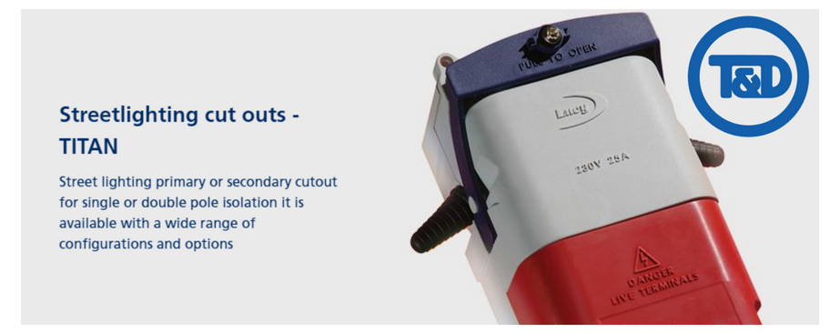
Lucy Zodion Titan2 cut outs are supplied as standard with features that ensure the street lighting technicians task is considerably easier.
The Lucy Titan2 cam lever handle enables effortless release of the Lucy fuse carrier in one movement and there is plenty of cabling space to terminate a wide variety of conductor types and sizes.
Insulated or brass cable gland plates are also available for when dual or triple entries are required.
High quality engineering thermoplastics make the Lucy Zodion Titan2 range the ideal choice to withstand heavy use in demanding locations.
Lucy Zodion Titan2
Street Lighting Cut Outs Range
- Single or double pole cut outs
- Single or twin fuse cut outs
- Brass or insulated gland plate options
- Extensive trough options
- 1 up, 2 up, 1 up 1 down circuit arrangements

Street lighting Cut Outs – Titan2
TITAN2 SINGLE & DOUBLE POLE CUT OUTS
PRODUCT SPECIFICATION
Should you require any technical support and advise in order to select the correct street lighting cut out please do not hesitate to contact us.
| Lucy Cut Out Part No | Fuseways | Components | Description | Cable Entry | Image |
| Titan2 (NT06) double pole single fuse cut out, complete with earth block, and brass plate with: | |||||
| THM0006032 | 1 | 2 x 20mm grommets | NT06-TT-NG12 |  |
 |
| THM0010170 | 1 | 2 x BW20 brass glands | NT06-TT-NG18 | |
|
| THM0010121 | 1 | 2 x 20mm tubes | NT06-TT-NG25 | |
|
| THM0031147 | 1 | 2 x 25mm tubes | NT06-TT-NG26 | |
|
| Titan2 (NT06) double pole single fuse cut out, complete with earth block, small extension trough, and brass plate with : | |||||
| THM0010657 | 1 | 2 x 20mm grommets | NT06-TT-NEF-NG12 | |
 |
| THM0017257 | 1 | 2 x 20mm grommets | NT06-TT-NEF-NG13 | |
|
| THM0013678 | 1 | 2 x BW20 brass glands | NT06-TT-NEF-NG18 | |
|
| THM0010211 | 1 | 2 x 20mm tubes | NT06-TT-NEF-NG25 | |
|
| THM0010212 | 1 | 2 x 25mm tubes | NT06-TT-NEF-NG26 | |
|
| Titan2 (NT06) double pole single fuse cut out, complete with earth block, large extension trough, and brass plate with : | |||||
| THM0036546 | 1 | 2 x 25mm grommets | NT06-TT-NED-NG13 | |
 |
| THM0037191 | 1 | 2 x 20mm tubes | NT06-TT-NED-NG25 | |
|
| THM0028975 | 1 | 2 x 25mm tubes | NT06-TT-NED-NG26 | |
|
| THM0016546 | 1 | 2 x BW25 glands and 1 x 25mm grommet | NT06-TT-NEE-NG82 |  |
|
| Titan2 (NT08) double pole twin fuse cut out, complete with earth block, and brass plate with : | |||||
| THM0009901 | 2 | 2 x 20mm grommets | NT08-TT-NG12 | |
 |
| THM0012689 | 2 | 2 x BW20 brass glands | NT08-TT-NG18 | |
|
| THM0013303 | 2 | 2 x 20mm tubes | NT08-TT-NG25 | |
|
| THM0014521 | 2 | 2 x 25mm tubes | NT08-TT-NG26 | |
|
| Titan2 (NT08) double pole twin fuse cut out, complete with earth block, small extention trough, and brass plate with : | |||||
| THM0010563 | 2 | 2 x 20mm grommets | NT08-TT-NEF-NG12 | |
 |
| THM0029334 | 2 | 2 x 25mm grommets | NT08-TT-NEF-NG13 | |
|
| THM0014659 | 2 | 2 x BW20 brass glands | NT08-TT-NEF-NG18 | |
|
| THM0011708 | 2 | 2 x 20mm tubes | NT08-TT-NEF-NG25 | |
|
| THM0010841 | 2 | 2 x 25mm tubes | NT08-TT-NEF-NG26 | |
|
| Titan2 (NT08) double pole twin fuse cut out, complete with earth block, large 2-way extention trough, and brass plate with : | |||||
| THM0037298 | 2 | 2 x 25mm grommets | NT08-TT-NED-NG13 | |
 |
| THM0037316 | 2 | 2 x 20mm tubes | NT08-TT-NED-NG25 | |
|
| THM0037323 | 2 | 2 x 25mm tubes | NT08-TT-NED-NG26 | |
|
| Titan2 (NT10) double pole twin fuse cut out, complete with earth block, 3-way extension trough, and brass plate, with : | |||||
| THM0027135 | 2 | 3 x 25mm tubes | NT10-NED-NEE-NT6-NG61 | |
 |
| THM0012093 | 2 | 3 x 20mm grommets | NT10-NEC-NT6-NG68 | |
|
| THM0010786 | 2 | 2 x 25mm grommets, 1 x 20mm grommet | NT10-NEC-NT6-NG52 | |
|
Lucy Zodion Titan2
Specifications
| Specifications |
|
| Options |
|

Lucy DNO Cut Outs Offer Street Lighting Contractors Improved Cable Termination Access
Lucy Lighting Titan SLF
Single Pole Cut Outs
With its low body split line to maximise cabling access, the Lucy Lighting Titan SLF is the simplest exponent of the single pole cut outs.
Tough, engineering grade thermoplastics and fully electroplated brass componentry ensure that the Lucy SLF street lighting cut out will have a long, reliable service life.
The Lucy Zodion Titan MC040SLF cam operated fuse handle ensures that electrical disconnection takes place prior to the fuse carrier being extracted by the street lighting contractor.
Lucy Zodion MC040SLF Single Phase Cut Out Specifications
- Cut out designed and tested in accordance with BS 7654:1997
- 25A maximum fuse rating
- Accepts fuse links to BS 88 Part 1, AC 16 tag type
- IP22 rating
- Single pole isolation
- Single fuse
- Electroplated brass terminals with serrated bores
- Max. cable size; 16sqmm stranded copper, 25sqmm solid aluminium
- Cable entry via PVC grommets as standard
- Outgoing cables exit below horizontal to form drip loop
- Sealing wire facility
| Lucy Zodion Titan MC040SLF Single Phase Cut Out Dimensions | |
| Height | 150mm |
| Width | 76mm |
| Depth | 60mm |
| Order Details For MC040SLF Street Lighting Cut Out | |
| Order Code | Description |
| MC040SLF 25A SLCO TYPE 1 (SNE) | Separate Neutral and Earth |
| MC040SLF 25A SLCO TYPE 2 (CNE) | Combined Neutral and Earth |
➡ For further information about how Lucy Zodion provide control and power distribution products for street lighting applications, please review the Lucy Titan (Cut-outs) and Lucy Trojan (Isolators) ranges of products.
- Further Reading: Street Lighting Cut Outs From Lucy Zodion – WPD Approved (G81)
Complete range of LV Cable Accessories ➡
Cable Breakouts | Cable Caps | Cable Lugs | Cable Cleats | Cable Trough | Cable Duct | Feeder Pillars | for 11kV/33kV/66kV networks see MV HV Joints & Terminations

Pfisterer | Nexans Euromold | Prysmian | Cable Joints & Terminations MV HV

Cold Shrink by 3M | Joints | Abandonment | Terminations | Low Voltage LV Cables
Lead Wiping | A Disappearing Cable Jointers Skill Video Tutorial
April 16th, 2019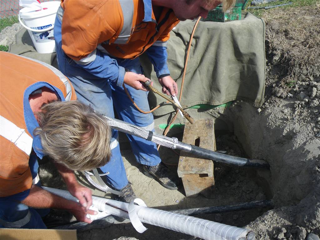
How to Wipe Lead Cables
Prior to Cable Jointing
-
uploaded by - Chris Dodds Thorne & Derrick Sales & Marketing Manager
Heat shrink cable joints for jointing paper or polymeric insulated cables (PILC or XLPE) with lead sheaths are specified for Low Voltage power distribution systems in the oil, gas and petrochemical industries where underground cables are exposed to waterlogging and corrosive liquids and vapours – cable construction including the lead sheath cover or jacket protects against penetration and degradation of electric cable insulation by hydrocarbon contaminants (whether underground or airborne).
Today, lead wiping has virtually disappeared from the cable jointers skill-set as more modern techniques, such as constant force spring armour and lead earthing continuity kits, which are integral to 3M hydrocarbon resistant cable joint kits have become commonplace. The modern day trend towards the manufacture and adoption of Polymeric (XLPE EPR insulated) cables has further reduced the demand for jointers with competency to work, maintain and splice using PILC type cables.
Cable Jointing & Lead Wiping
Credit: ThunderboltNZ
Lead Sheath Cutting & Removal From Paper Insulated Cables
Due to Occupational Health & Safety problems with handling lead and associated fumes, lead wiping has been replaced by jointing the cable sheaths using copper earth braid and constant force springs.

Lead Sheath Wiping
Pictured : A cable repair being conducted on a 200 pair (400 wire) lead-sheathed, paper-insulated cable (PILC). The photo illustrates the difficult conditions under which cable jointers often have to work. The gas lantern is required for both lighting and heating as it is important that the paper insulation of the individual wires do not become damp.
The joining of paper-insulated, lead-sheathed cables is not an easy task. Each 200 pair joint can take over two days to complete. The wires are identified by a colour code and are layered in a particular way: a common mistake when repairing these cables is to join pair number 1 to pair number 200 (i.e. 180 degrees out of phase). Each wire is individually joined together and covered by a paper sleeve. The photo below shows a close-up of the cable being spliced with some pairs having been joined and the remainder temporarily folded back out of the way.

Cable Splicing
LV Cable Joints (Low Voltage Cables)
Thorne & Derrick stock and distribute LV Joints in Cold Shrink, Heat Shrink or Resin Cast technologies – multicore and multi-pair cable joints are available for immediate backfill and energisation of Low Voltage power, control and instrumentation cables 600V/1000V 3.3kV.
Further Reading
- LV Cable Diversion 4 Core PILC to 4 Core Wavecon Straight Joint
- PILC Replacement & Cable Longevity
- Cable Splicing At The Lazy Q Ranch
Complete range of LV Cable Accessories ➡
Cable Breakouts | Cable Caps | Cable Lugs | Cable Cleats | Cable Trough | Cable Duct | Feeder Pillars | for 11kV/33kV/66kV networks see MV HV Joints & Terminations
Pfisterer | Nexans Euromold | Prysmian | Cable Joints & Terminations MV HV
Cold Shrink by 3M | Joints | Abandonment | Terminations | Low Voltage LV Cables
Fire Walls & Fire Risk Hazards Of Electrical Equipment – BS EN 61936-1 : 2010
April 16th, 2019BS EN 61936-1:2010 Fire Walls
The following information and clauses concerning fire walls is extracted from BS EN 61936-1:2010.
Power Installations Exceeding 1kV a.c. Common Rules
8.7 Protection Against Fire 8.7.1 General
Relevant national, provincial and local fire protection regulations shall be taken into account in the design of the installation.
NOTE: Fire hazard and fire risk of electrical equipment is separated into two categories: fire victim and fire origin.
Precautions for each category should be taken into account in the installation requirements.
- precautions to fire victim:
- space separation from origin of fire;
- flame propagation prevention:
physical layout of the substation,
liquid containment,
fire barriers (e.g. REI fire-resistant materials 60/90),
extinguishing system;
- precautions to fire origin:
- electrical protection;
- thermal protection;
- pressure protection;
- fire resistant materials.
Care shall be taken that, in the event of fire, the escape and rescue paths and the emergency exits can be used (see 7.1.6).
The user or owner of the installation shall specify any requirement for fire extinguishing equipment. Automatic devices to protect against equipment burning due to severe overheating, overloading and faults (internal/external) shall be provided, depending on the size and significance of the installation.
Equipment in which there is a potential for sparks, arcing, explosion or high temperature, for example electrical machines, transformers, resistors, switches and fuses, shall not be used in operating areas subject to fire hazard unless the construction of this equipment is such that flammable materials cannot be ignited by them.
If this cannot be ensured, special precautions, for example fire walls, fire-resistant separations, vaults, enclosures and containment, are necessary.
Consideration should be given to separating different sections of switchgear by fire walls. This can be achieved by means of bus ducts which penetrate the fire wall and which connect the sections of the switchgear together.
8.7.2 Transformers, Reactors
In the following sub-clauses, the word ‘transformer’ represents ‘transformers and reactors’.
For the identification of coolant types, see 6.2.2.IEC 61100 classifies insulating liquids and transformer oils according to:fire point and net caloric value (heat of combustion).
Three classes have been defined:
Class O, if the fire-point is less than or equal to 300 °C. (e.g Mineral Oil).
Class K, if the fire-point is above 300 °C. (e.g MIDEL 7131 and MIDEL eN 1024).
Class L, if the insulating liquid has no measurable fire-point.(e.g. Xiameter PMX-561).
IEC 60076-11 classifies dry-type transformers in terms of their behaviour when exposed to fire. The fire hazard associated with transformers of outdoor and indoor installations is dependent on the rating of the equipment, the volume and type of insulating mediums, the type and proximity and exposure of nearby equipment and structures.
The use of one or more recognized safeguard measures shall be used in accordance with the evaluation of the risk.
♦ IEC 60076-11:2018 Power Transformers – Part 11: Dry-type Transformers
NOTE: For definition of risk, see ISO/IEC Guide 51.
Common sumps or catchment tanks, if required, for several transformers shall be arranged so that a fire in one transformer cannot spread to another. The same applies to individual sumps which are connected to the catchment tanks of other transformers; gravel layers or pipes filled with fluid can, for example, be used for this purpose.
Arrangements which tend to minimize the fire hazard of the escaped fluid are preferred.
8.7.2.1 Outdoor Transformer Installations
The layout of an outdoor installation shall be such that burning of a transformer with a liquid volume of more than 1,000 litres will not cause a fire hazard to other transformers or objects, with the exception of those directly associated with the transformer. For this purpose, adequate clearances, G, shall be necessary.
Guide values are given in Table 3. Where transformers with a liquid volume below 1,000 litres are installed near combustible walls, special fire precautions may be necessary, depending on the nature and the use of the building.
If automatically activated fire extinguishing equipment is installed, the clearance G can be reduced.
If it is not possible to allow for adequate clearance as indicated in Table 3, fire-resistant separating walls with the following dimensions shall be provided:-
a) between transformers (see Figure 6) separating walls. For example EI 60 in accordance with the Official Journal of the European Community, No. C 62/23:
height: top of the expansion chamber (if any), otherwise the top of the transformer tank;
length: width or length of the sump (in the case of a dry-type transformer, the width or length of the transformer, depending upon the direction of the transformer);
b) between transformers and buildings separating walls. For example EI 60; if additional fire separating wall is not provided, fire rating of the building wall should be increased, for example REI 90 (see Figure 7) in accordance with the Official Journal of the European Community C 62/23.
Table 3 – Guide Values For Outdoor Transformer Clearances
| Transformer Type | Liquid Volume | Clearance G to | ||
| Other transformers or non-combustible building surface (m) | Combustible building surface (m) | |||
| Oil insulated transformers (O) | 1000 <…..< 2000 | 3 | 7.5 | |
| 2000 <…..< 20000 | 5 | 10 | ||
| 20000 <…..< 45000 | 10 | 20 | ||
| < 45000 | 15 | 30 | ||
| Less flammable liquid insulated transformers (K) without enhanced protection | 1000 <…..< 2000 | 1.5 | 7.5 | |
| ≥3800 | 4.5 | 15 | ||
| Clearance G to building surface or adjacent transformers | ||||
| Less flammable liquid insulated transformers (K) without enhanced protection | Horizontal (m) | Vertical (m) | ||
| 0.9 | 1.5 | |||
| Dry-type transformers (A) | Fire behaviour class | Clearance G to building surface or adjacent transformers | ||
| Horizontal (m) | Vertical (m) | |||
| F0 | 1.5 | 3.0 | ||
| F1 | None | None | ||
NOTE 1: Enhanced protection means:
- tank rupture strength
- tank pressure relief
- low-current fault protection
- high-current fault protection
For an example of enhanced protection, see Factory Global standard 3990 (33) or equivalent.
NOTE 2: Sufficient space should be allowed for periodic cleaning of resin-encapsulated transformer windings, in order to prevent possible electrical faults and fire hazard caused by deposited atmospheric pollution.
Three classes have been defined:
Class O, if the fire-point is less than or equal to 300 °C. (e.g Mineral Oil)
Class K, if the fire-point is above 300 °C. (e.g MIDEL 7131 and MIDEL eN 1024)
Class L, if the insulating liquid has no measurable fire-point.(e.g. Xiameter PMX-561)
8.7.2.2 Indoor Transformer Installation In Closed Electrical Operating Areas
Minimum requirements for the installation of indoor transformers are given in Table 4.
Table 4 – Minimum Requirements For The Installation Of Indoor Transformers
| Transformer Type | Class | Safeguards |
| Liquid Volume | ||
| ≤ 1000 I | El 60 respectively REI 60 | |
| ≤ 1000 I | El 90 respectively REI 90 or El 60 respectively REI 60 and automatic sprinkler protection | |
| Less flammable liquid insulted transformers (K) | Nominal power/max | |
| Without enhanced protection | (no restriction) | El 60 respectively REI 60 or automatic sprinkler protection |
| With enhanced protection | ≤ 10 MVA and UM ≤ 38 kV | El 60 respectively REI 60 or separation distances 1.5m horizontally and 1.5m vertically |
| Dry-type transformer (A) | Fire behaviour | |
| F0 | El 60 respectively REI 60 or separation distances 0.9m horizontally and 1.5m vertically | |
| F1 | Non combustible walls | |
NOTE 1: REI represents the bearing system (wall) whereas El represents the non-load bearing system (wall) where R is the load bearing capacity, E is the fire integrity, I is the thermal insulation and 60/90 refers to time in minutes.
NOTE 2: Enhanced protection means:
- tank rupture strength
- tank pressure relief
- low-current fault protection
- high-current fault protection
For an example of enhanced protection, see Factory Global standard 3990 (33) or equivalent.
NOTE 3: Sufficient space should be allowed for periodic cleaning of resin-encapsulated transformer windings, in order to prevent possible electrical faults and fire hazards caused by deposited atmospheric pollution.
Doors shall have a fire resistance of at least 60 min. Doors which open to the outside are adequate if they are of low flammability material. Ventilation openings necessary for the operation of the transformers are permitted in the doors or in adjacent walls. When designing the openings, the possible escape of hot gases shall be considered.
8.7.2.3 Indoor Transformer Installations In Industrial Buildings
For all transformers in industrial buildings, fast-acting protective devices which provide immediate automatic interruption in the event of failure are necessary.
Transformers with coolant type O require the same provisions as in 8.7.2.2.
For all other liquid-immersed transformers, no special arrangements in respect of fire.
protection are required, except for the provisions for liquid retention in case of leakage and the provision of portable fire extinguishing apparatus suitable for electrical equipment.
Dry-type transformers (A) require the selection of the correct fire behaviour class depending on the activity of the industry and on the material present in the surroundings. Fire extinguishing provisions are advisable, particularly for class F0.
NOTE: For all transformers in industrial buildings, additional fire precautions may be necessary, depending on the nature and use of the building.
8.7.2.4 Indoor Installations In Buildings Which Are Permanently Occupied By Persons
In high-voltage installations, located in public or residential buildings, special conditions shall be observed in accordance with existing standards or national regulations.
8.7.2.5 Fire in the vicinity of transformers
If there is an exceptional risk of the transformer being exposed to external fire, consideration shall be given to
- fire-resistant separating walls;
- gas-tight vessels capable of withstanding the internal pressure generated;
- controlled release of the hot liquid; fire extinguishing systems.
8.7.3 Cables
The danger of the spread of fire and its consequences shall be reduced, as far as possible, by selecting suitable cables and by the method of installation.
The cables may be assessed by reference to the following categories:
- cables without particular fire performance characteristics;
- cables (single) with resistance to flame propagation (IEC 60332 series);
- cables (bunched) with resistance to flame propagation (IEC 60332 series);
- cables with low emission of smoke (IEC 61034-1);
- cables with low emission of acidic and corrosive gases (IEC 60754-1 and IEC 60754-2);
- cables with fire-resisting characteristics (IEC 60331-21 or IEC 60331-1).
Cables in trenches and buildings shall be laid in such a way that the regulations regarding fire safety of the building are not adversely affected. For example, to avoid fire propagation, holes or cable ducts through which the cables go from one room to another shall be sealed with suitable fire proof and resistant material.
A physical separation or different routing of power circuits from the control circuits for high voltage equipment is recommended if it is necessary to preserve the integrity of the latter as long as possible following damage to the power circuits.
Where necessary, a fire alarm and fire extinguishing systems shall be installed in cable tunnels and in cable racks in the basement of control buildings.
8.7.4 Other Equipment With Flammable Liquid
For all equipment, such as switchgear which contains more than 100 l of flammable liquid in each separate compartment, special fire precautions as specified for transformers may be necessary, depending on the nature and use of the installation and its location.
Figure 6 – Separating Walls Between Transformers
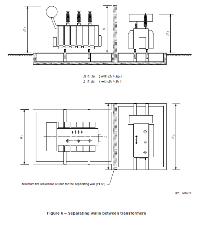
Figure 7 – Fire Protection Between Transformer & Building
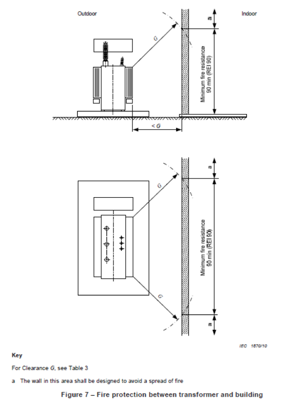
Key
For Clearance G. see Table 3
a) The wall in this area shall be designed to avoid a spread of fire
Further Reading
Transformer Oils – 11kV 33kV 66kV Substation Transformer Oil Refilling, Sampling & Analysis
Utilising Distribution Transformers To Optimise Solar
11kV Transformers | Introducing Amorphous Core HV Transformers
VIDEO How To Verify Total Absence of Voltage By The Push Of a Button
THORNE & DERRICK SPECIALIST ELECTRICAL DISTRIBUTOR
The 11kV Specialists
Thorne & Derrick distribute the most extensive range of 11kV Cable Jointing, Terminating, Pulling & Installation Equipment – we service UK and international clients working on underground cables, overhead lines, substations and electrical construction at 11kV and up to and EHV transmission and distribution voltages.
- Key 11kV Products: MV-HV Cable Joints & Terminations, Cable Cleats, Duct Seals, Cable Transits, Underground Cable Protection, Copper Earth Tapes, Cable Jointing Tools, Feeder Pillars, Cable Ducting, Earthing & Lightning Protection, Electrical Safety, Cable Glands, Arc Flash Protection & Fusegear.
- Distributors for: 3M Cold Shrink, ABB, Alroc, Band-It, Catu, Cembre, Centriforce, CMP, Elastimold, Ellis Patents, Emtelle, Furse, Lucy Zodion, Nexans Euromold, Panduit, Pfisterer, Polypipe, Prysmian, Roxtec.

LV – Low Voltage Cable Joints, Glands, Cleats, Lugs & Accessories (1000 Volts)

MV HV – Medium & High Voltage Cable Joints, Terminations & Connectors (11kV 33kV EHV)

Cable Laying – Underground Cable Covers, Ducting, Seals & Cable Pulling Equipment
T&D, CATU Electrical Safety & Arc Flash Protection Specialists for SAP’s, Linesmen, Jointers & Electrical Engineers – Largest UK Stockist
ALVIN by EA Technology | Identify LV Electrical Equipment Faults
April 15th, 2019
ALVIN by EA Technology Identify LV Electrical Equipment Faults
-
uploaded by - Chris Dodds Thorne & Derrick Sales & Marketing Manager
ALVIN by EA Technology
The ALVIN (Automatic Low Voltage Intelligent Network) has been developed by EA Technology (EATL) and is supporting customers and saving time and money through speedy fault and location detection.
ALVIN Reclose is the next generation of supply-restoration reclose equipment, providing Network Operators with invaluable support in reducing costs and delivering better customer service.
ALVIN Reclose meets the immediate needs of Network Operators to improve customer service on ageing, low voltage networks, while providing the foundation for future automation and communication schemes.
EA Technology’s ALVIN Reclose is the most advanced, compact, cost-effective solution available on the market enabling intelligent automation and fault restoration on low voltage electrical and cable networks.

ALVIN Reclose
ALVIN & Western Power Distribution
Stoke Plant Team Manager at Western Power Distribution Steve Weddell said: “We use the ALVINs on intermittent faults where existing electrical equipment has failed to locate the issue or where visibility of the underlying problem is required. It provides visibility to power quality information which helps to locate the fault or power quality issue.”
Steve and his team worked closely with EA Technology for 12 months and the team has since achieved 100% success rate in detecting issues where we have deployed the ALVIN on known faults and problem circuits.

Western Power Distribution Using ALVINs On Intermittent Faults
Stoke Engineering Specialist David Phillips gave a real case example of where the ALVIN has helped customers. “In early 2018 we received reports of flickering lights in Alrewas in the Stoke distribution patch. Power quality devices were fitted but no meaningful cause for the disturbance was found.
The issue continued for several months.
During a visit to EA Technology my colleague and I discussed the matter and we decided to use the ALVIN as an experiment to investigate the cause. On installation, the problem was immediately found and the electrical power fault rectified within two days.”
The device records the voltage and current waveforms associated with a collection of brief faults, which disappear (self-heal) before a fuse operates. The ALVIN fits in a standard low voltage holder and which, on detection of a fault, will break the circuit and disconnect supplies, wait for approximately thirty seconds, then reclose and reconnect the circuit.
The ALVIN fits in a standard low voltage holder and which, on detection of a fault, will break the circuit and disconnect supplies, wait for approximately thirty seconds, then reclose and reconnect the circuit.
In 2017 EA Technology launched a new LV (Low Voltage) Cloud data service which enabled the voltage and current waveform visualisation and fault location service to be provided.

Identify LV Electrical Equipment Faults With ALVIN By EA Technology
We have had several sets of ALVINs since 2016. Approximately 12 months ago, we bought the communication equipment which enabled it to communicate to the LV Cloud. These sets have been distributed between Nottingham and Stoke depots where the ALVIN systems have been deployed to manage and locate problematic LV faults.
David explained: “The waveform data is captured by the device and the status of customer supplies is confirmed by text or email. The severity and frequency of pre-fault activity can be used to indicate supply interference as well as implying the likelihood of an impending fault or probability of getting a good thermal reading or ‘sniff’ of fault gases to confirm the suspected location fault.
David concluded: “We have found the units to be extremely versatile and currently work in close partnership with EA technology in exploring the possibilities of these devices and future development.”

ALVIN Reclose
ALVIN
Business Benefits
- Ability to identify and ‘self-clear’ multiple transients and overload faults so reducing engineering costs and delivering improved customer service
- Simple, retrofit installation with no hidden ‘start up’ costs means the low-cost ALVIN Reclose offers excellent cost/benefits justification.
- flexible features give businesses exactly what they need now. The device is the foundation building block of a range of low-cost add-on devices and services, making it ‘future-adaptable’
- ALVIN Reclose uses the latest technologies, ensuring the safety of employees and customers
- The ALVIN Reclose device allows for more effective asset management, increasing reliability, efficiency and safety at lower costs
Automatic Low Voltage Intelligent Network
Features
- Automatic ‘self-clearing ‘of transient and overload faults,
- Supply restoration with no need for manual intervention
- High quality specification, functionality and reliability
- ‘All-in-one’ mechanism tests and restores power automatically
- Unique SafeON™ technology ensures power can be restored safely
- Fully self-contained, it does not require any auxiliary components
- Full load, network analysis and diagnostics are available through the external data port
- Ready for future use: it is the foundation for a range of low-cost, add-on products and services
- The only retrofit product with arc-less switching for improved network protection.
- Fitting is simple, fast, safe and compatible with existing 92mm fuse holders
- factory programmed to suit different customer requirements
- Comprehensive training, together with on-call service support
ALVIN Technical Specification
| ITEM | RATING |
| Rated Operating Voltage | 275V phase to neutral on either pole 440V across poles |
| Rated Insulation Voltage | 690V |
| Rated Operating Current | 400A or 500A as thump option for ALVIN RecloseITTM version |
| Operating frequency | 50Hz |
| Rated making capacity | 80kA |
| Rated breaking capacity | 80kA |
| Overcurrent trip characteristic | Inverse time-based on 315A & 400A BS88-2 It zones |
| Ambient air temperature | -25°C to +45°C |
| Operating cycles | 1000 |
| Voltage measurement | ±1.5% 50V to 253V AC RMS |
| Current measurement | ±1% >200A, ±2A ≤200A |
| Harmonic monitoring | Yes |
| Directional Fault Indicators | Yes |
| Fault location ready | Yes |
| Making on faulty cable | SafeONTM with current limiting to 2.4kA |
| Standards applied | IEC 60947-2, IEC 61000, IEC60255 |
EA Technology
EA Technology are a global provider of end to end power engineering solutions and provide expert consultancy, innovative instruments, skills training, technical services and more.

Thorne & Derrick Specialist Electrical Distributor
Established since 1985, T&D distribute the most extensive range of LV, MV & HV Cable Jointing, Terminating, Pulling & Installation Equipment – contact us today for a competitive quotation.
Key Products : MV Joints & Terminations, Cable Cleats, Duct Seals, Cable Transits, Underground Cable Protection, Jointing Tools, Feeder Pillars, Cable Duct, Earthing & Lightning Protection, Electrical Safety, Cable Glands, Arc Flash Clothing Protection & Fusegear.
Distributors for : 3M, Pfisterer CONNEX, Nexans Euromold, Elastimold, Catu, Roxtec, Emtelle, Centriforce, Lucy Zodion, Alroc, Hivotec, Cembre, Prysmian, Ellis Patents, ABB & Furse.

T&D Providers Of Jointer Training Courses By Pfisterer CONNEX & Nexans Euromold
A European First | Electrical Safety Trainers – Protect Wearers Against Electrical Risks Up To 18kV
April 15th, 2019
Electrical Safety Trainers – Protect Wearers Against Electrical Risks Up To 18kV
-
uploaded by - Chris Dodds Thorne & Derrick Sales & Marketing Manager
Electrical Safety Trainers
Rock Fall has developed what it said is the first Electrical Safety Trainer available in Europe.
A multi-award winning second generation family owned business, Rock Fall has positioned itself at the forefront of the electrical safety footwear industry as a leading manufacturer of linesmans boots and dielectric insulating boots to meet the ever-changing demands of the power transmission and distribution industry.
Recognising the strong growth and focus on clean energy and sustainability around the world Rock Fall have developed the first Electrical Safety Trainers available in Europe.
Certified against European and International Electrical Hazard standards the safety trainers are designed to protect wearers against electrical risks up to 18kV in accordance with the ASTM F2412-11 test method.
The range is in stock in the UK and available exclusively from the largest PPE resellers in the UK, including Thorne & Derrick.
The range, which has already been recognised by the industry for Innovation at the recent Professional Clothing Awards is driving quick and significant growth in Australia and New Zealand, with major electrical contractors specifying the products for their electrical operations.
The electrical hazard trainers comply with European and American Standards:
- EN ISO 20345:2011 SB P E FO WRU SRC
- ASTM F 2413-11 1/75 C/75 EH PR

Electrical Hazard Trainer
Speaking about the development, Richard Noon said:
“Electrical risks are increasing as the prominence of hybrid and fully electric vehicles continues to grow. In manufacture, service and at the end of life these vehicles must be handled safely using correctly specified electrical safety equipment.
Electric Vehicles aren’t the only driver for this, as we increase the pressure on our electricity networks, there will be even greater demand for preventative maintenance and work on live lines.
Increased pressure can cause accidents and to have an additional item of PPE to be the last line of defence, in our opinion is critical.
We have seen from the great improvements in Safety Management during the Crossrail project.
With HS2 electrification high on the agenda, from the view of a Electrical Safety Equipment manufacturer it’s important that our industry makes the most of these major infrastructure projects.”
ARC FLASH PROTECTION, CLOTHING & PPE FOR LINESMEN, JOINTERS & UTILITY WORKERS

Coveralls | Helmets | Gloves | Insulating Gloves | Insulating Matting | Electrical Safety Equipment MV HV

LV, MV & HV Jointing, Earthing, Substation & Electrical Eqpt
Thorne & Derrick International are specialist distributors of LV, MV & HV Cable Installation, Jointing, Duct Sealing, Substation & Electrical Equipment – servicing UK and global businesses involved in cable installations, cable jointing, substation, overhead line and electrical construction at LV, 11kV, 33kV and EHV.
THORNE & DERRICK Product Categories: Duct Seals | Cable Cleats | Cable Glands | Electrical Safety | Arc Flash Protection | Cable Jointing Tools | Cable Pulling | Earthing | Feeder Pillars | Cable Joints LV | Joints & Terminations MV HV


