TTS Green Trough is fast becoming the cable management product of choice and installation on Network Rail infrastructure and rail cable protection where versatility and speed of installation of a cable trough is paramount.
The ground level or elevated polymer cable trough management system comprising troughs and lids conforms to Network Rail NR/L2/TEL/00013 for protection and management of trackside cables including LV Low Voltage and HV High Voltage signal, telecoms and power cables up to 25kV.
In May 2014, Network Rail issued Safety Bulletin 323 which prohibited with immediate effect the manual lifting, carrying and team handling of C143 conventional concrete troughs and troughing.
In January 2015, Network Rail issued Safety Bulletin NRB 15/01 mandating a risk assessment policy for all troughing products by using the MAC tool together with the troughing elements risk chart. On 22 April 2015 ORR issued the following Notices:
Prohibition Notice PN40/22042015 prohibiting “single individual employees or contractors manually lifting or carrying 10 or more units of cable troughs or troughing weighing 40kg or more in a 12 hours period” anywhere on Network Rail Infrastructure.
Prohibition Notice PN70/22042015 prohibiting “two employees or contractors manually lifting or carrying 10 or more units of cable troughs or troughing weighing 70kg or more in a 12 hours period” anywhere on Network Rail Infrastructure.
Both of the Prohibition Notices apply immediately. Continuing the activity would be a criminal offence.
A further Improvement Notice IN/25/22042015 requires Network Rail to undertake a suitable and sufficient assessment of the risk to employees, and contractors working under their control, from manually handling rail cable troughing weighing 25kg and more. That assessment will need to identify the measures necessary to control the risks identified.
This additional work is required by 25 October 2015. Further information will be communicated when the work is complete.
Immediate Action Required
- Compliance with the requirements of the Prohibition Notices is required immediately.
- If you are about to manually handle concrete troughing products then you must have an approved, site-specific risk assessment. If you haven’t then stop, request that a risk assessment is undertaken by a competent individual and implement any resulting actions before continuing work
- All staff and contractors who specify, manage, plan, authorise and carry out manual handling activities relating to the delivery, installation, renewal or disposal of troughing materials must comply in full with the guidance of the HSE manual handling MAC assessment tool or a suitable equivalent
- If your work involves any equivalent risk with other loads that you move manually, apply the same controls, derived from risk assessment.
Cable Troughs & Troughing
Selection Table
| Concrete Trough Variants |
Description |
Full Weight Concrete (kg) |
Full Weight Half Length Concrete (kg) |
Reduced Weight Concrete (kg) |
Reduced Weight Half Length Concrete (kg) |
TSS Green Trough Variants |
Full Weight Polymer (kg) |
Full Weight Half Length Polymer (kg) |
| C/1/6 |
Straight Trough |
37 |
19 |
24 |
12 |
TS120S |
6 |
|
| C/1/7 |
Straight Trough |
49 |
25 |
32 |
16 |
TS150S |
8 |
|
| C/1/38 |
Transition |
50 |
25 |
35 |
18 |
TT150/200 |
1 |
|
| C/1/8 |
Straight Trough |
71 |
36 |
46 |
23 |
TS200S |
14 |
|
| C/1/9 |
Straight Trough |
55 |
28 |
36 |
18 |
TS200S |
14 |
|
| C/1/31 |
Trough Bend |
55 |
28 |
36 |
18 |
TS430B |
12 |
|
| C/1/35 |
Transition |
58 |
29 |
38 |
19 |
TT200/250 |
1 |
|
| C/1/10 |
Straight Trough |
62 |
31 |
40 |
20 |
TS250S |
|
9 |
| C/1/34 |
Trough Tee |
60 |
30 |
39 |
20 |
TS250T |
10 |
|
| C/1/36 |
Transition |
65 |
33 |
44 |
22 |
TT200/250 |
1 |
|
| C/1/33 |
Transition |
66 |
33 |
43 |
22 |
TT250/300 |
2 |
|
| C/1/29 |
Straight Trough |
70 |
35 |
46 |
23 |
TS300S |
16 |
|
| C/1/82 |
Trough Tee |
76 |
38 |
49 |
25 |
TS430T |
21 |
|
| C/1/32 |
Transition |
77 |
39 |
53 |
27 |
TT300/150 |
2 |
|
| C/1/82 |
Transition |
77 |
39 |
50 |
25 |
TT300/430 |
2 |
|
| C/1/61 |
Transition |
82 |
41 |
53 |
27 |
TT430/120 |
3 |
|
| C/1/80 |
Trough Tee |
83 |
42 |
54 |
27 |
TS300T |
13 |
|
| C/1/62 |
Transition |
85 |
43 |
55 |
28 |
TT430/200 |
3 |
|
| C/1/44 |
Transition |
88 |
44 |
60 |
30 |
TT300/430 |
3 |
|
| C/1/63 |
Transition |
88 |
44 |
57 |
29 |
TT430/250 |
3 |
|
| C/1/23 |
Trough Tee |
89 |
45 |
64 |
32 |
TS200T |
9 |
|
| C/1/45 |
Transition |
94 |
47 |
60 |
30 |
TT200/430 |
3 |
|
| C/1/43 |
Straight Trough |
115 |
58 |
75 |
38 |
TS430S |
|
15 |
| C/1/81 |
Trough Tee |
140 |
70 |
91 |
46 |
TS430T |
21 |
|
SE MAC Tool Assessment of Concrete & Polymer Trough Products
| GREEN |
The risks are low but you should further assess the manual handling activity considering the time duration, repetitiveness of task and the site environment. |
| AMBER |
You should examine and assess the planned manual handling activities closely giving full consideration to alternative mechanical means. |
| PINK |
There is a high level of risk from manual handling of these products. A full re-evaluation of the risks is required prior to any further activity. |
| PURPLE |
There is a very high level of risk and manual handling of these products is prohibited unless a detailed risk assessment demonstrates that this may be performed safely. |
| RED XX |
These items are now effectively obsolete for manual handling compliance with the Network Rail prohibition notices. |
TSS 90 Series | TSS 135 Series | TSS 200 Series | TSS 150 Series | TSS 300 Series | TSS 430
Thorne & Derrick

More Info
Thorne & Derrick are leading Specialist Distributors & Stockists of LV, MV & HV Cable Installation, Jointing, Substation & Electrical Equipment to the Rail industry.
Products: Duct Seals | Cable Cleats | Cable Glands | Electrical Safety | Arc Flash Protection | Cable Jointing Tools | Cable Pulling | Earthing | Feeder Pillars | Cable Joints LV | Joints & Terminations MV HV
GRP Cable Trough | GRC Cable Trough | Concrete Cable Trough | Cable Ducting
G81
The following materials framework according to ENA Engineering Recommendation G81 Part 5 “Framework for Materials Specification for Industrial & Commercial Underground Connected Loads Up To & Including 11kV” includes the approved Cable Joints, Terminations & Connectors approved for use with HV Switchgear, HV/LV Transformers & Substations on the Western Power Distribution (WPD) network.
Should you require any technical support or have any commercial requirements about G81 Approved 11kV/33kV Cables & Accessories please do not hesitate to contact Thorne & Derrick Sales Team.
WPD
List Of Approved Materials & Suppliers 11kV 33kV 66kV
| Component |
National Specification |
Manufacturer |
Size Type |
| Earth Rods |
ENATS 43-94 |
W Furse
CBS Products
ERICO (GB) |
|
| Cable Marker Tape |
ENATS 12-23 and BS EN12613 |
Fiberweb Geosynthetics Ltd |
150mm x 0.1mm x 365m |
| Fuses (LV) |
BS88 Part 5 |
Cooper Bussmann Ltd
Lawson Fuses Ltd |
100A Slot 92mm
160A Slot 92mm
200A Slot 92mm
250A Slot 92mm
315A Slot 92mm
355A Slot 92mm
400A Slot 92mm
500A Slot 92mm
630A Slot 92mm |
| Link Boxes |
|
Prysmian (2 or 4 way)
Sicame (2 or 4 way) |
Insulated Resin Filled
2W Sicame Mk3
4W Sicame Mk 3 |
| Cut-Outs (100A) |
BS7657 |
WT Henley |
Single Phase 100A
Three Phase 100A
SNE Link/Earth Terminal |
| Cut-Outs (Heavy Duty) |
|
Lucy Switchgear |
400A Cut Out
600A Cut Out |
| Street Lighting Cut-Outs |
|
Lucy Zodion |
CNE 1 Pole
CNE 2 Pole
SNE 1 Pole |
| Connectors LV Mains Joints |
IEC 61238-1 |
TE Connectivity (B&H) |
MSIP – Service
UST – Straight
USBT1 – Straight
UBR – Branch
UBRD – Cut Main
BCNE-3UTB – Neutrals
TAI, TA II & TAIII Consac Neutral
VETA-33P-UTB |
| Connectors LV Service |
IEC 61238-1 |
TE Connectivity (B&H) |
BTC – Straight
BTCL 6-130W – Straight & Branch
SSIPC |
| Connectors LV Terminations |
IEC 61238-1 |
TE Connectivity (B&H) |
LVET Cable Lugs
BET Cable Lugs
ML Cable Lugs |
| LV Cable Joints |
NAT ER C81/3 or BS EN50393 |
TE Connectivity |
Various depending on cable being jointed |
| 11kV Jointing Compounds |
HD 628 & 629 |
Lovink |
Lovisil |
| 11kV EPR Single Core Cable |
BS7870 Part 4.10 |
Prysmian Cables,
Tratos Cables, Nexans Cables,
Quintas & Quintas Cables |
630sqmm |
| 11kV EPR Triplex Cable Cu |
BS7870 Part 4.10 |
Prysmian Cables,
Tratos Cables, Nexans Cables,
Quintas & Quintas Cables |
300sqmm | 400sqmm |
| 11kV EPR Triplex Cable Al |
BS7870 Part 4.10 |
Prysmian Cables,
Tratos Cables, Nexans Cables,
Quintas & Quintas Cables |
95sqmm | 185sqmm | 300sqmm |
| 11kV Terminations Indoor & Outdoor |
HD 628 & HD 629 |
TE Connectivity |
70-95sqmm Indoor CSTI3121-GB01,
185-300sqmm Indoor CSTI-3131-GB01,
400-630sqmm CSTI-3141-GB01 &
Outdoor 70-95sqmm Outdoor CSTO-3121-GB01,
185-300sqmm Outdoor CSTO-3131-GB01
400-630sqmm CSTO-3141-GB01 |
| 11kV Straight Joints |
HD 628 & HD 629 |
Lovink |
K85 – 95-185 sqmm
K95 – 185-400 sqmm |
| 11kV Stop Ends |
HD 628 & HD 629 |
Lovink |
K85 – 95-185 sqmm
K95 – 185-400 sqmm |
| 11kV Live Break Elbows & Bushing Well Insert |
HD 628 |
Nexans (Euromold) |
11kV 95sqmm |
| 11kV Separable Connectors |
HD 629.1 S1 |
Nexans (Euromold) |
630sqmm Single – K440TB/G32- TMBC400-630 MWS
630sqmm Double – K440TB/G- P2-32 TMBC 400-630MWS;
300sqmm – K400TB/G-25-TMBC120-300 MWS |
| HD 629.1 S1 |
Nexans (Euromold) Lucy Sabre Mk2 RMU |
K430TB/G |
| 33kV EPR Single Core Cable |
HD 7870 Part 4 |
Prysmian Cables,
Tratos Cables, Nexans Cables,
Quintas & Quintas Cables |
185, 300, 400, 630 and 800sqmm Single Core EPR |
| 33kV Joints |
HD 629 |
Lovink |
Single Core Poly / Poly 185 to 1000sqmm
Single Core Trif Joint 185 to 400sqmm
Stop Ends 185 to 1000sqmm |
| 33kV Terminations |
HD 629 |
Ensto |
185 Through to 1000sqmm EPR Indoor & Outdoor
Partially Insulated Terminations |
| 33kV Inner Cone Type Size 3 CONNEX Terminations |
HD 629 |
Pfisterer |
185sqmm to 800sqmm EPR Size 3 CONNEX Cable Terminations |
| 33kV Outer Cone Terminations |
HD 629 |
Euromold |
185sqmm to 800sqmm EPR (M)430 TB/G and
(M)440TB/G Outer Cone Terminations |
| 66kV Joints |
HD 629 |
3M |
Single Core Poly / Poly 185 to 1000sqmm
Single Core Stop Ends 185 to 1000sqmm |
| 66kV Terminations |
HD 629 |
3M |
185 Through to 1000sqmm EPR Outdoor Partially
Insulated Terminations |
| 66kV Inner Cone Type Size 4 CONNEX Terminations |
HD 629 |
3M |
185 Through to 1000sqmm
EPR Outdoor Partially Insulated Terminations |
| 66kV Outer Cone Terminations |
HD 629 |
Pfisterer |
185sqmm to 1000sqmm EPR Size 4 CONNEX Terminations |
| 66kV Connectors |
HD 629 |
Euromold |
185sqmm to 1000sqmm EPR (P)430 TB/G and
(P)440TB/G Outer Cone Terminations |
Thorne & Derrick International
T&D distribute the most extensive range of MV & HV Jointing & Terminating, Installation & Cable Pulling Equipment – we service UK and international clients working on underground cables, overhead lines, substations and electrical construction at LV, 11kV, 33kV and EHV transmission and distribution voltages.
- Key Products: MV-HV Cable Joints & Terminations, Cable Cleats, Sealing Cable Ducts, Cable Transits, Underground Cable Protection, Cable Jointing Tools, Feeder Pillars, Cable Ducting, Copper Earthing, Electrical Safety, Cable Glands, Arc Flash Protection & Fusegear.
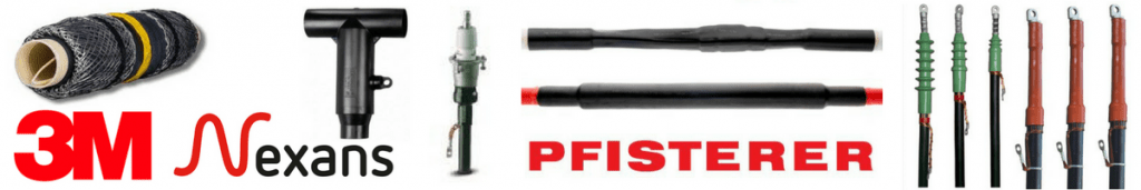
- Distributors for: 3M, ABB, Alroc, Band-It, Catu, Cembre, Centriforce, CMP, Elastimold, Ellis Patents, Emtelle, Furse, Lucy Zodion, Nexans Euromold, Pfisterer, Polypipe, Prysmian, Roxtec.
Switchgear Cable Terminations
T&D distribute MV-HV Switchgear Cable Terminations to suit 11kV/33kV connections into air, oil and gas insulated switchgear or transformers including heat shrink, cold shrink and separable connectors for both inner cone and outer cone bushings from leading manufacturers including Nexans Euromold, 3M and Pfisterer.
♦ See more: Heat Shrink Cable Terminations 11kV 33kV | Cold Shrink Cable Terminations 11kV 33KV

MV HV – Medium & High Voltage Cable Joints, Terminations & Connectors (11kV 33kV EHV)
More…
T&D’s Power Blog covers: LV MV HV & EHV Transmission & Distribution, Substations, Switchgear, Cable Jointing & Termination, Cable Fault & Repair, Underground Cables.
➡ Visit Power Blog.


Arc Flash Clothing & Protection
Arc flash
Arc flash accidents are not nearly as rare as you would think and the hazards they create are severe. In wind turbines, these hazards are magnified.
Installing and maintaining wind turbines can be a tricky job and it is important to understand the importance of staying safe and Protecting Lives by wearing arc flash clothing including an arc flash helmet, insulating boots and arc flash gloves.
In fact, most employers wouldn’t dream of permitting their teams on site without adequate protection and workers themselves are more than clued up when it comes to the latest electrical safety equipment requirements.
However, the same can’t be said when it comes to the potentially fatal risk posed by an Arc Flash – a relatively misunderstood, but extremely common type of electrical explosion facing those working on onshore or offshore, private or commercial wind turbine projects.
Arc Myth Busted: Did you know most arc flash accidents occur in LV systems?
Especially legacy switchgear and switchboards undergoing the The Three R’s – retrofit, refurbishment or repair. Modern technology Low, Medium & High Voltage Electrical Equipment with integral insulated arc-free busbar assemblies, arc flash relays and arc quenching switchgear, such as manufactured by Eaton, minimises but does not eliminate the risk of arc flash completely.
Of course, the best way to avoid arc flash is to de-energise – nevertheless, Arc Flash can occur on power systems inadvertently made live while undergoing maintenance under planned isolation procedures.

Image: Safety Management Services, Inc.
A Wind Turbine Arc Flash Incident
The Clear & Present Danger
Although no injuries were reported – thankfully – the devastation inflicted to the wind turbine pictured below is extreme, to the point of destruction. That turbine is beyond repair.
Now imagine just for a moment if the wind turbine had been manned or the incident had involved manpower – the feasibility of providing urgent medical treatment to an injured worker in a nacelle at high level is complicated. Often, the physical workplace location of the wind turbine prevents rapid rescue and emergency intervention due to remoteness and accessibility – quite often offshore. By September 2018, the UK wind power sector consisted of 9,088 wind turbines with a total installed capacity of over 20.1 gigawatts: 12,222 megawatts of onshore capacity and 7,907 megawatts of offshore capacity.
Technicians from Vestas, the company that oversees the maintenance of the turbine, attended site in April 2018 to complete a damage assessment. An expert from the company, who specialises in examining wind turbines that have experienced major malfunctions and fires, began an investigation into how the fire occurred.
An engineer hired as part of the insurance claim eligibility process was able to look at the wind turbine and investigate the cause of the fire. According to the engineer’s findings, the turbine experienced an arc flash that caused an electrical fire.
Officials with Vestas have declared the nacelle a total loss, though the tower and foundation are reusable, and will be providing the client with the costs for options ranging from decommissioning of the wind turbine to replacement of the unit.
Clean-up at the site to remove the damaged nacelle occured over the summer but is not expected to be completed before the end of the year.
So don’t ignore The Arc – a few attributable costs of arc flash induced outages and downtime:
- Revenue loss incurred from inability to generate electricity. £100K’s-ish. Minimum.
- Outage period until repairs are complete. Weeks? Months??
- Replacement of damaged or destroyed equipment. Financially, don’t think about it.
- Consequential reputation damage. Immeasurable.


Image: Crown Estates
What Is An Arc Flash?
Hotter than the sun (around 20,000°C) and louder than a bullet, an Arc Flash is when an arcing fault releases dangerous levels of radiant energy, which vaporises metal that spews from the arc. The air is super-heated causing pressure waves that can propel individuals across rooms and create a deadly molten shrapnel.
It goes without saying; the extreme temperatures of an Arc Flash can burn clothing and human skin within fractions of a second, even if the operative is situated five or six metres away from the Arc Flash event. It can also result in an explosive pressure wave that can throw workers across the room and a sound blast that can rupture eardrums.
An Arc Flash event is also accompanied by a bright flash which can cause temporary or even permanent blindness.
Treatment for those that survive an incident can require years of skin grafts, hospital stays and rehabilitation – they may never recover sufficiently to regain their lifestyle, so it’s safe to say that choosing the appropriate PPE is key when it comes to Arc Flash safety.
Posing A Risk
Electrical in nature, Arc Flash poses a substantial risk to those working in the wind industry which is constantly growing in importance due to its potential to contribute significantly to our national energy needs.
When working on wind turbines or windfarms, Arc Flash incidents can occur in both low voltage environments as well as high voltage, with particular reference to the following incidents…
- Opening energised electrical cabinets and verifying zero energy (testing dead)
- Securing and removing lock out and tag out (LOTO) devices
- Conducting trouble shooting on energised equipment and parts
- Working on near or exposed live conductors
- Breaking ground to install turbines
It is worth noting that the above incidents are of broadly the same severity whether the turbine is part of a large commercial windfarm or one of the growing number of small scale turbines installed by businesses.
How To Protect Yourself Against Arc Flash
Arc Flash protection is found in specialist clothing and garments for “head-to-toe” protection – everything from arc flash coveralls to arc flash trousers.
Enhanced and effective arc flash protection is safely achieved by wearing layers of protective clothing and garments manufactured from inherent fibres and which feature specific Arc Flash resilient components. Without the correct high-quality garments, arc protection levels will be compromised.
In addition to quality, it’s important to consider the longevity of the garment – depending on how it’s manufactured it may lose its effectiveness. Always look for products that feature Arc Flash protective qualities in the thread, as opposed to just a sprayed material, which will lose its impact over time.

Arc Flash Risks & How To Prevent Them – Wind Turbines & Windfarms
Overview of Arc Flash Clothing | Contact us to discuss your garment and PPE requirements, we can mitigate risk with guidance on safe working practices and by providing appropriate worker clothing that offers advanced Arc Flash Protection that saves lives every day. Whether working on underground cables or overhead lines, here is a selection of workwear clothing – contact us to discuss your requirements;


 | Nexans (Euromold JTS MONO) | Pfisterer (CONNEX SEANEX) | 11kV 33kV 66kV Medium & High Voltage Cable Accessories")
HV Cable Joints, Terminations & Connectors | Approved Stockists & Distributors | 3M Electrical (Cold Shrink) | Nexans (Euromold JTS MONO) | Pfisterer (CONNEX SEANEX) | 11kV 33kV 66kV Medium & High Voltage Cable Accessories

CATU CM-50 Medium Voltage Static Ground Discharger
Static Discharge Sticks
Product Launch – MV Medium Voltage Static Ground Discharge Stick
Thorne & Derrick supply the CATU CM-50 Static Discharge Stick used for medium/ high voltage overhead lines, busbars and substation use up to 33kV. The CATU discharge stick complies to the IEC 60855 standard and is used to safely dissipate electrostatic charges.
♦ IEC 60855-1:2016 Standard | Live Working – Insulating foam-filled tubes and solid rods. Part 1: Tubes and rods of a circular cross-section.
CATU CM-50 static discharge stick is an insulating orange tube with a diameter of 39mm and made of epoxy fibreglass – equipped with 6 metre of copper cable, cross section section 6sqmm, PVC insulated.
Static discharge sticks are designed to safely remove the static charge after de-energising of medium/high voltage power systems – this includes draining voltage retaining components before maintenance work is performed up to 33kV. The discharge sticks are equipped with hand guard and grip protection with sufficient electrical safety clearance against physical contact with medium/high voltages.
Static discharge sticks are available for higher voltage applications – contact us to discuss your MV HV EHV Electrical Safety Equipment requirements.

IEC 60855 | Discharge Sticks for Medium Voltage Substations
Catu CM-50 Static Discharge Stick Specification
| For Use On Medium Voltage Lines & Conductors Up To |
33kV |
| Hand Guard At Length |
0.65m |
| Copper Alloy Contact Probe Length |
80mm |
| Overall Discharge Stick Length |
1.6m |
| Weight |
2.3kg |
T&D are the UK’s largest stockis of CATU Electrical Safety Equipment of products for underground, overhead line and substation safety at LV, MV and HV cable networks.

Cable Lugs & Crimps – Hexagonal v Indent Methods of Crimping
Crimping Cables
Thorne & Derrick International, based in the UK, are leading suppliers of cable lugs and associated crimping tools for Low, Medium & High Voltage Cables and Power Systems – this series of articles by Klauke discusses the theory and practise of installing compression type cable lugs and connectors for use with copper and aluminium conductors.
Klauke cable lugs and crimping tools are used by Jointers, Linesmen, Panel Builders and Electrical Engineers to install underground cables and overhead line conductors on power, transmission and distribution networks including LV MV & HV systems, 11kV-33kV.
➡ Download 2018 Klauke Cable Lugs catalogue and see the complete range of tools for cutting and crimping cables.
In this Article we cover both hexagonal crimping and indent crimping of cables including the following:
- The hexagonal crimp: the most common type of crimp for cable lugs and connectors
- Indent crimps representing the traditional electrical cable crimp profile
- Intensive indent crimp is guaranteed a permanent and “deep acting” connection
- Quad point crimps: the advantage is the way the centric force is applied and that no crimping tool dies are needed
- Gastight oval crimps are being used predominantly in aggressive environments
➡ See DIN Standard Cable Crimping for information about connecting and terminating cables in accordance with the German national organisation for standardisation – see DIN 48083 for specific information about lugs, die sets and crimping tools for hexagon compression type cable termination.
Which Cable Crimping Method Is Correct?
Indent of Hexagonal?
Cable crimp types and cable lugs at a glance.
Initially the subject covering crimping profiles seems complicated; the electrical installer is confronted with a number of different cable types, each requiring different cable lugs or connectors and a professional crimping method and associated crimp tools.
This combination depending on material, design and application requires the correct crimping profile to be used.
The following will give a review of the most common cable crimp profiles the electrician or cable jointer should be familiar with when crimping copper or aluminium cables:
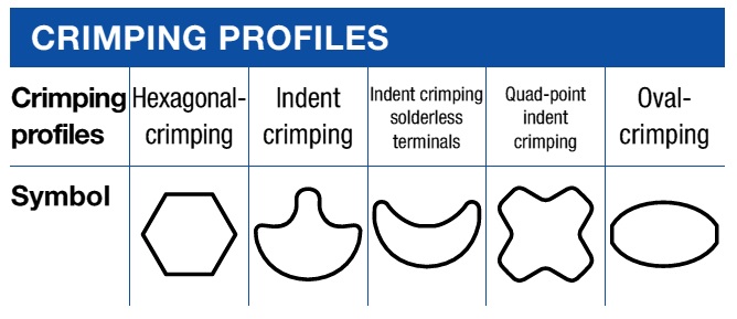
Cable Crimping Profile Chart
Cable Lugs For Copper & Aluminium Cables
Hexagonal Crimps
The most common type of crimping for copper and aluminium cables, lugs and connectors is the hexagonal crimp as this crimp profile is suitable for both copper and aluminium conductors.
The range of applications covering hexagonal crimps includes the crimping of conductors as per VDE-0295-categories 2, 5 and 6 and the processing of non-tension connections of aluminium cables using aluminium splices per DIN48201 (Copper Stranded Conductors) Part 1 and aluminium ropes per DIN EN 50182 (Conductors for Overhead Lines – Round Wire Concentric Lay Stranded Conductors).
Note
DIN VDE 0295 VDE 0295:1992-06 Standard (Conductors of Cables, Wires & Flexible Cords for Power Installation) is now Withdrawn and replaced by DIN EN 60228 VDE 0295:2005-09 Standard (Conductors of Insulated Cables).

A hexagonal crimp is suitable for both copper and aluminium conductors. The advantage is the central force which is applied consistently from all directions by the crimping tool.
The advantage of a hexagonal crimp is the central force which is applied consistently from all directions and over a larger area during the crimping operation. During this crimping operation the individual strands of the conductor are being homogeneously compressed preventing any damage.
The result is a strong mechanical connection. Due to the even compression the hexagonal crimps are also suitable for application in medium and high voltage cable terminations, connections and joints. However, these advantages are faced with some limitations.
The complete compression of wire strands using a hexagonal crimp and standard crimping dies is not possible. This means standard hexagonal crimps are not gas-tight (see gas-tight oval crimps at the end of this article).
Therefore it should be observed that a professional hexagonal crimp requires the use of crimping dies which are matched exactly with material (aluminium or copper) and dimensions (cross section area and conductor construction).
Hexagonal Crimps – DIN Type
Copper & Aluminium
Hexagonal crimps differ in two versions: one relates to the standard hexagonal crimp in accordance with DIN 48083 Part 4 and the other to the manufacturers related hexagonal crimp. The standardised hexagonal crimp allows cable lugs and connectors according to DIN 46235 to be crimped with certified crimping dies per DIN 48083 Part 4.
DIN 46235 defines the fields of application, dimensions and the marking of compression cable lugs – compression cable lugs to DIN 46235 standard can be used for single, multi-fine and superfine stranded conductors.

The standardized hexagonal crimp allows cable lugs and connectors per DIN 46235 to be crimped with certified crimping dies per DIN 48083 part 4.
Marking on DIN cable lugs provide essential information as to manufacturer, dimensions and design of the cable lug. These markings indicate for instance which crimping tools and crimping dies need to be used to achieve a DIN compliant crimp. This designation is next to the manufacturers’ marking.
For instance “KL 18…” stands for KL: manufacturer (in this case Klauke) and 18 for the die code. The correct die code is a condition of a professional DIN crimp: crimping dies used in the crimping tool need to comply with the die code shown on the cable lug. The mirror image of the die code can be seen on the surface of the crimping dies. After the crimping operation the die reference code can be seen on the barrel of cable lug as part of a visible and recordable quality control procedure.
The die code corresponds approximately to the tube diameter of the cable lug.
The range of copper lugs is approximately from 6 to 58 which correspond with the cross sections from 6sqmm to 1000sqmm. Hexagonal crimping dies per DIN 48083 Part 4 for aluminium lugs and connectors are described in accordance with the tube dimensions of lugs per DIN 46239 and connectors per DIN 46267 Part 2 (Non Tension-Proof Compression Joints For Copper Conductors).
The alternative
Apart from DIN standard hexagonal crimps the crimping of copper and particularly of cable types per VDE 0295 Classification 2 (Conductors Of Cables, Wires & Flexible Cords For Power Installation) also allows for a manufacturer related hexagonal crimp to be used.
Prestigious manufacturers such as Klauke provide hexagonal crimping dies tested and approved to IEC 1238 (Compression & Mechanical Connectors For Power Cables With Copper or Aluminium Conductors – Part 1: Test Methods & Requirements) for crimping standard copper cable lugs as per BS EN 13600 (Copper & Copper Alloys – Seamless Copper Tubes For Electrical Purposes). For commercial reasons such cable lugs are often used in control and switch cabinets. Despite offering cost benefits, there is no reduction in cable termination quality.
Important: The use of manufacturer related crimping dies and cable lugs are not con-trolled through the die codes. Instead it depends more on the cross section of the cable being used indicated in sqmm, the cable lug and the die reference. The square mm size is mirror printed on the crimping surface of the crimping dies.
Every manufacturer is responsible for the electrical and mechanical durability of connections crimped with there own tools. As a safe and professional crimp is dependent on accurately matching suitable crimping dies to the cable lugs, Klauke always recommends using the manufacturers approved crimping tools.
Proven & Tested – Indent Crimp Lugs
The indent crimp represents the oldest electrical crimp profile. This crimp profile is solely suitable for the processing of copper and is often used in control panels and switch cabinets operated within a range of 1000V.
The permissible cable range includes stranded conductors per VDE 0295 Classification 2 and also fine stranded and compacted conductors per Classification 5 and 6sqmm up to 400sqmm. These conductors can be processed with R and F series tubular cable lugs.
Generally two different types of indent crimps are used: the W-profile for cross sections from 0.5sqmm up to 16sqmm and the classic single indent crimp for cross sections from 6sqmm up to 240sqmm.
Klauke crimping tools offer the possibility to indent crimp cross sections up to 400sqmm.
The characteristics of both versions are identical: indent crimps are always special crimping operations particularly required for fine stranded and compacted conductors to secure a permanent connection.

Indent (side indent) are always special application crimps which are primarily used for crimping fine stranded and compacted conductors to secure a permanent connection. The applied crimp profiles depend on the cross section of the conductor and type of cable lug.
The real benefit of indent crimping is the simple operation and procedure for which normally hand operated crimping tools can be used. The applied crimp profile depends on the cross section of cables, cable lugs and connectors to be used.
Since the indent crimp does not represent a standardised crimp it is imperative to only use high quality materials and tools approved per IEC 1238 originating from one manufacturer.
Only in this case the electrician is safeguarded utilising cable lugs, connectors and tools which are matched to each other and which provide and guarantee a safe connection.
copper & insulated materials
Indent Crimps
Indent crimps have been specifically developed for processing connections of cable lugs according to DIN 46234 and connectors per DIN 46341 part 1, form A+B, which in turn are suitable for conductors of VDE 0295 Classification 2, 5 and 6.
Cable lugs and connectors complying with these standards feature a particular large outside diameter which will accept all types of cables without any problem.
The intense indent crimp ensures that despite of the large outside diameter a long lasting and “deep acting” crimp is achieved.

Class 1 round single-stranded (rs) conductor (commonly known as solid conductor. Class 2 round multi-stranded (rm) conductor. Class 5 fine-stranded conductor 5 (commonly known as flexible conductor. Class 6 ultrafine-stranded conductor 6 (commonly known as highly-flexible conductor.
The permitted cross sections range from 0.5sqmm up to 240sqmm. An indent crimp is also suitable for Klauke F-type cable lugs ranging from 10sqmm up to 300sqmm.
F-type cable lugs feature a larger diameter, funnel shaped tube to accept fine stranded and compacted types of cables per VDE 0295 Classification 5 and 6 without any splitting.
An indent crimp is also suitable to crimp pre-insulated terminals in accordance with DIN 46234 where the crimp pierces the cable insulation. To avoid that the insulation is damaged during the cable crimping operation it is imperative to only use cable lugs with a high quality insulation and appropriate crimp profiles.

The intensive indent crimp is only guaranteed when matched materials are used despite the large outside diameters a permanent and “deep acting“ connection will be achieved.
The indent and the side indent are also non-standard types of crimp but can also be used for standard cable lugs such as terminals per DIN Standard 46234. For this reason here it is also important to use crimping tools and materials from a single quality manufacturer. Materials incorrectly matched are disadvantaged further due to the extreme stresses applied during use. Once a single strand has been lost mechanical and electrical failures in the connection may become inevitable leading to cable failures.

Cable lugs with a high quality insulation and appropriate crimp profiles ensures that the insulation does not become damaged during the cable crimping operation.
No dies required – Quad point Cable crimps
The quad point crimp originates in the USA and is being used mainly in panels and switch cabinets up to 1000V. These are also used in other electrical connections i.e. in drive systems for locomotives where this type of crimp offers the perfect cable termination solution.
This crimp profile is suitable for cable lugs and connectors ranging from 10sqmm up to 300sqmm in combination with cables per VDE 0295 Classification 2, 5 and 6.

The quad point crimp is suitable for cable lugs and connectors with cross sections ranging from 10sqmm
up to 300sqmm in combination with cable types per VDE 0295 classification 2, 5 and 6.
Attention: Application for use with pre- insulated cable lugs and connectors is not allowed. The advantage over a simple indent crimp is the way the centric force is applied and that no crimping dies are needed. This means that with just one crimping tool all the above mentioned cross sections can be processed. The quality of the crimp depends solely on the force and quality of the crimping tool used.
Gastight Oval crimp Lugs
Gastight oval crimps are being used pre-dominantly in the motor industry and in aggressive environments such as agricultural operations or chemical industries with potentially explosive atmospheres characterised by flammable gases in hazardous areas. A gastight cable termination connection means that both conductor and cable lug or connector is compacted together so tightly that no notable gap exists to prevent gas migration.

Gastight oval cable crimps provide for a permanent connection and electrical conductivity. The ingress of fluid or a gas is not possible under normal atmospheric conditions. An oxidation of the individual crimped strands is prevented and an increase in resistance is avoided.
This means that the ingress of fluid or a gaseous medium is not possible under normal atmospheric conditions. An oxidation of the individual crimped strands is prevented and an increase in resistance is avoided.
For this reason gastight oval crimps provide for a permanent cable connection and good electrical conductivity.
A gastight connection can be tested by inspecting the polished cross section of the cable lug. There is no restriction to specific types of cables; therefore all types of conductors are suitable for gastight oval cable crimps.
To meet the high technical requirements of gastight connections it is absolutely imperative to use only high quality branded crimping tools and connecting material.
Outlook: Which crimp profile for the professional solution?
To ensure that durable crimping connections are achieved, specific crimping operations are required. In our next edition we will feature the various crimp profiles in detail and will explain what needs to be observed to obtain professional high quality connections, joints and cable terminations.
Further Reading
Review other Blogs in this series of articles about Cable Lugs, Crimping Cables & Tools:
Cable Lugs – Crimping Applications & Standards
Copper Cable Lugs For Special Applications
Indent Crimping Of Cables – Benefits & Limitations
Cable Lugs & Crimping Using The Hexagonal Crimp Method
DIN Standard – Crimping & Compressing Aluminium Cable Lugs & Connectors
Copper & Aluminium – Crimping CU-AL Cables
Electrically Driven Crimping Tools For High Volume Applications
LV MV HV Cable Accessories & Substation Electrical Equipment
Thorne & Derrick are Specialist Distributors of leading manufacturers of Cable Accessories, Jointing & Installation Equipment.
LV MV HV cable accessories used to joint, terminate, connect, cleat and gland power cables to air and gas insulated substations, transformers, switchgear and overhead line networks.
Hover over our Interactive Logo Grid to learn more about our product ranges.
LV 600/1000V ◊ MV 11kV 33kV ◊ HV 66kV 132kV
Substation & Overhead Line Electrical Safety Equipment
Manufactured by CATU Electrical to enable the safe construction, maintenance and repair of underground cables and overhead lines network up to EHV (400kV).
T&D - CABLES ♦ JOINTS ♦ TERMINATIONS ♦ CONNECTORS ♦ GLANDS ♦ CLEATS ♦ CRIMPS & LUGS ♦ DUCT ♦ SEALS ♦ ARC FLASH PPE
EARTHING ♦ FEEDER PILLARS ♦ JOINTERS TOOLS ♦ CABLE CUTTING & CRIMPING TOOLS ♦ COLD SHRINK ♦ HEAT SHRINK ♦ FUSES


")